Abstract
The article analyzes the movement of a wheelset along a path that is unequal in length with wave wear of the rails. The authors studied the influence of a force external disturbance on the parametric system “wheel-rail”. The problem under consideration is solved on the basis of a mathematical model of the interaction of a wheel pair and an unequal track, taking into account the additive effect of unequal stiffness on a railway vehicle. It is shown that taking into account the longitudinal uneven elasticity of the railway track makes it possible to more accurately determine the resonant regions and evaluate the decrease or increase in the acceleration level and the amplitudes of bouncing of the unsprung mass of the rolling stock.
Highlights
- Analysis of forced oscillations
- Additive effect of unequal stiffness on a railway vehicle
- Unsprung mass of the rolling stock
- Nonlinear oscillation theory
- Mechanical system is linear
- System of linear algebraic equations
1. Introduction
The analysis of problems associated with the vibrations of mechanical systems is a very voluminous branch of applied mechanics. This section is based on fundamental foreign and domestic research in the field of nonlinear oscillation theory. This branch of mechanics has effective methods and a wide range of solved problems. At the same time, the development of modern transport technology constantly puts forward new and urgent problematic issues. To ensure the possibility of designing rolling stock in the field of optimizing various parameters that provide the required level of safety, driving performance and comfort, various methods are used.
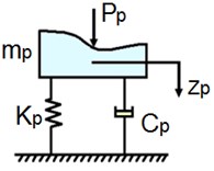
Analysis of publications on the topics covered showed that V. A. Nekhaev [1] indicated the possibility of interaction between forced and parametrically excited oscillations. This problem was most fully studied by the German scientist T. Schmidt [2] and reduced to solving integro-differential equations. However, before starting to study the movement of a wheelset along a path that is unequal in length with wave wear of the rails, let us dwell on a simpler problem. Let us study the influence of external force perturbation on the parametric system, assuming that there is no physical connection between them. In other words, the excitation sources are independent of each other [3]. This will allow us to obtain an analytical solution to the problem and establish some preliminary information, for example, regarding the phase shift angle between force and parametric effects. As a design scheme for oscillations of the unsprung mass of the vehicle, we will accept the scheme shown in Fig. 1.
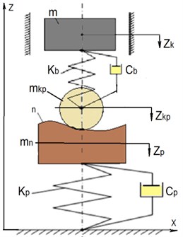
The design scheme of a conventional uniaxial vehicle is shown in Fig. 2. Let us agree that the vehicle can only perform vertical movements, in other words, it can only bounce. Therefore, the axis is directed vertically upwards, and it is also indicated – is the bouncing of the sprung mass of the vehicle, – is the bouncing of its wheelset, – is the bouncing of the “reduced” mass of the railway track, – is the pressure of the wheelset on the rails, and –is the stiffness and coefficient viscous friction of the axle box suspension of the vehicle, and – is the stiffness and coefficient of viscous friction in the way, – is the pressure of wheelset on rails.
Fig. 1Calculation scheme of oscillations of the unsprung mass of the crew
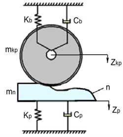
Fig. 2Calculation scheme of a conditional single-axle vehicle
For the convenience of solving the problem, we divide the mechanical system “crew-railway track” into two subsystems: the carriage and the track, shown below in Fig. 3.
Fig. 3Calculation schemes of a conditional single-axle car and railway track
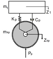
a) Wagon
b) Way
So, the mathematical model of the system, which was mentioned above, we have the following form:
where is the static deflection of the spring on which the load is suspended at its average value, is the amplitude of the force perturbation. Here we believe that the frequency of the parametric action is twice the frequency of the external force perturbation (this circumstance will simplify the solution of the problem). Although in principle, it is possible to introduce a small detuning of the system in frequency.
We will look for the solution of the differential Eq. (1) according to the general theory of such systems in the following form:
That, after simple transformations, will lead us to the system of linear algebraic equations (SLAE):
where – is the frequency detuning of the system, – is the a dimensionless coefficient characterizing viscous friction in the system (usually it is in the range from 0 to 0.7). Solving SLAE Eq. (4) and calculating the amplitude of oscillations according to the formula, we get the transfer function of the system in the form:
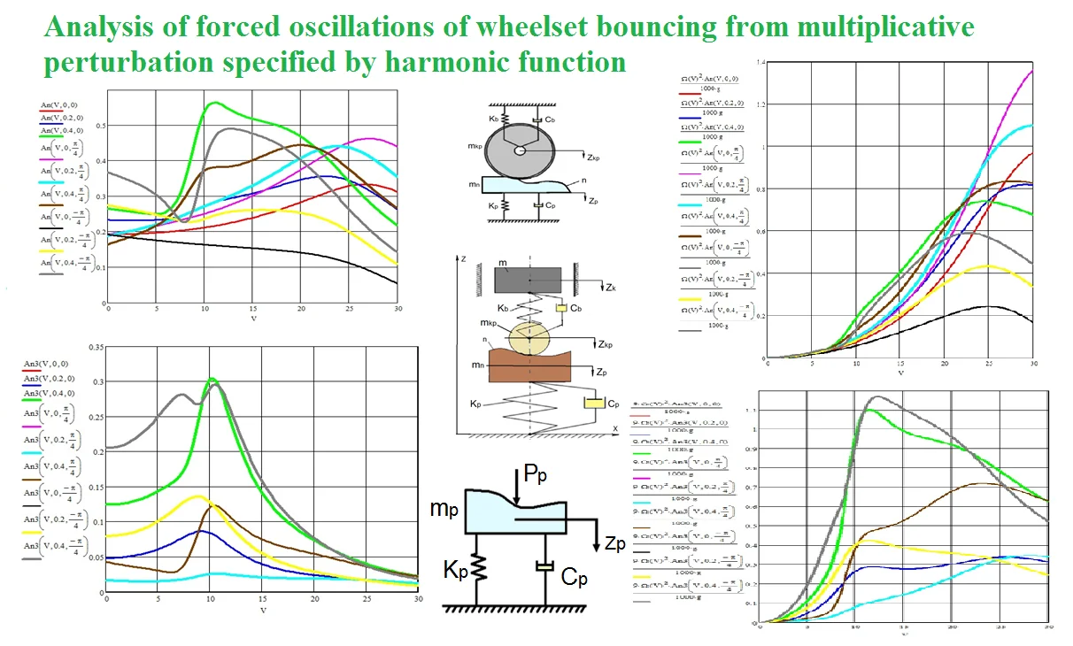
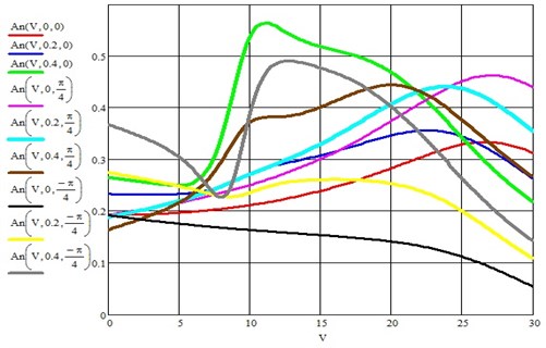
Graphic changes of this ratio are shown in Fig. 4.
Fig. 4Graphs of the change in the ratio of the steady-state amplitude to the static deflection of the elastic element of suspension of the load with a parametric excitation coefficient equal to 0; 0.2; 0.4 and three phase shift angles between perturbations 0, 45° and –45°
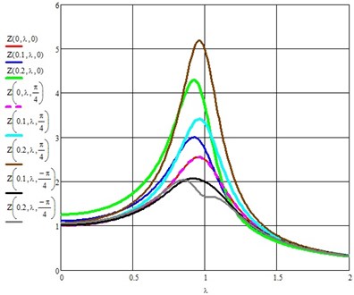
From the presented figure, it is easy to establish that if the phase shift between the power and parametric excitations is equal to /4, then the parametric perturbation enhances the amplitude of forced oscillations by 20,9 %, if the angle is /4, then the amplitude of forced oscillations decreases by 52,5 %. However, the indicated percentages were obtained in the resonance zone, when the natural frequency coincides with the frequency of the external force. Therefore, by creating parametric actions in a mechanical system subject to external force or kinematic disturbances, providing the necessary phase shift between disturbances, we can increase the efficiency of the crew vibration protection system [4].
The example of a parametric system considered above, which is affected by an external force perturbation, allowed us to establish some of their characteristic properties. Next, we turn to a special case when the length of the geometrical irregularity is twice as large or close to the distance between sleepers, which is an average of 0,54 m (depending on the diagram of the sleepers, in this case 1840 sleepers/km). This range of waves includes medium-wave undulating wear of rails; therefore, the case under consideration is not so far from reality. In addition, on the right side of the mathematical model of the interaction of a wheel set and a track that is unequal in length, there will be additional terms characterizing the additive effect of uneven stiffness on the vehicle. This circumstance, of course, complicates our task [5].
Taking into account the external perturbation from the path, we write:
here – is the phase shift angle between the parametric and external disturbances, – is the average static deflection of the railway track under the static pressure of the wheelset on the rails, – is the amplitude of the geometric unevenness on the rails. The first two terms on the right side of Eq. (6) are the additive component of the perturbation from the longitudinal, uneven elasticity of the track, and the following terms characterize the effect of a wave-like perturbation on the wheel pair of the vehicle. According to the methods of mathematics, the steady-state solution, if we further neglect the fourth and fifth harmonics, must be sought in the form:
Note that here we somewhat simplified the solution of the problem by assuming the exact fulfillment of the frequency relation between the driving force and the parametric perturbation . In reality, this relation is fulfilled approximately, but they differ little from each other, which, generally speaking, have little effect on the oscillation amplitudes. Let us differentiate this relation twice with respect to time, i.e. find the speed and acceleration of the generalized coordinate :
The standard operations associated with the substitution Eq. (7), Eq. (8) and trigonometric transformations lead us to the following system of equations for the oscillation amplitudes:
where is a matrix of coefficients that stand at unknown oscillation amplitudes to be determined, is the a vector of free terms. Their expressions are given below, since they are rather cumbersome. In addition, from the equation:
the constant was previously found, which is equal to: .
It was substituted into the system, which made it possible to reduce its order to 6. We will take the phase shift angle φ equal to either 0, or /4, or –/4, which will make it possible to reveal the relationship between parametrically excited and forced vibrations of the mechanical system:
A careful analysis of Eq. (10) indicates that the even and odd harmonics of solution Eq. (7) are not related to each other and, therefore, two problems can be considered separately, one of which is described by the following system of equations (this is possible because the considered mechanical system is linear):
and the other one looks like this:
where we have:
Fig. 5Influence of uneven elasticity of the track and locomotive speed on the amplitude of the vertical vibrations of the wheelset in mm
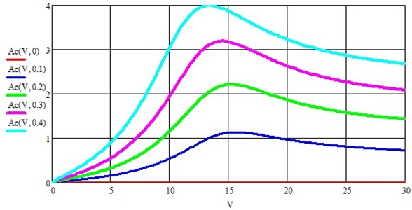
Taking into account the given initial data of the mechanical part of the locomotive and track: 0,25 ts∙s2/m, 0,056 ts∙s2/m, 23 ts, 304 ts/m, 7800 ts/m, 1 ts∙s/m, 27,3 ts∙s/m, 0,00284 m, 0,0002 m, were the following results are obtained, shown in the graphs below.
Fig. 5 shows a graph of the change in the amplitude of oscillations of the wheelset from the uneven elasticity of the track along the length.
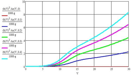
Fig. 6Acceleration of the wheelset in fractions of g from the longitudinal uneven elasticity of the railway track
The first and third harmonics of the wheelset bouncing due to the action of geometric irregularities on the rail tread surface are shown below in Figs. 7 and 8.
If the parametric perturbation coefficient is equal to 0.4, then the resonant amplitude of the wheelset bouncing does not exceed 4 mm, and the resonance develops at a speed close to 15 m/s (54 km/h). In the future, the amplitude decreases, but not very significantly [5-6].
Fig. 7Amplitude of the first harmonic of the wheelset bouncing due to the effect of geometric unevenness on the rail tread surface for three phase shift angles between parametric and kinematic disturbances φ= 0, φ=π/4 and φ=-π/4 in mm
The acceleration component of the vehicle's wheelset due to the longitudinal unevenness of the track is shown in Fig. 3, from which it is quite easy to see that the maximum acceleration can reach about 8 g at a vehicle speed of about 100 km/h and 0.4. Moreover, the acceleration increases both with an increase in the speed of the wheelset and with an increase in the coefficient of parametric excitation.
From the analysis of Figs. 7 and 8, it follows, first of all, to draw such an important conclusion that the amplitude of the third harmonic oscillations is about 50 % of the first. Since the system under consideration is linear, and the perturbation is represented by only one harmonic, the appearance of the third harmonic must be attributed to the action of a parametric perturbation [7]. The accelerations of the wheelset due to the action of harmonic geometric roughness are given in Fig. 9. It increases with increasing vehicle speed, although it is easy to detect resonance, which is blurred and develops in the speed range from 20 to 30 m/s and then decreases with increasing speed.
Fig. 8Amplitude of the third harmonic of wheelset bouncing due to the effect of geometric unevenness on the rail tread surface for three phase shift angles between parametric and kinematic disturbances φ= 0, φ=π/4 and φ=-π/4 in mm
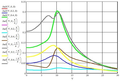
Fig. 9Acceleration of the wheelset of the vehicle from the action of harmonic geometric unevenness on the surface of the rails
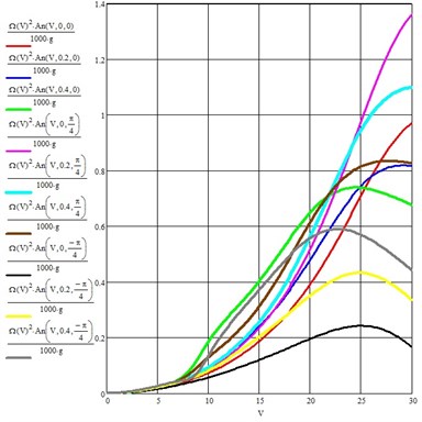
Fig. 10Acceleration of the wheelset of the vehicle on the third harmonic from the action of geometric irregularities on the surface of the rails
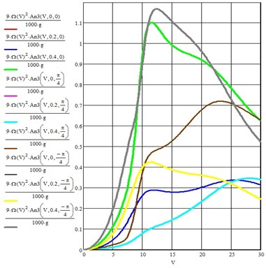
Note that the figure shows only the first harmonic of solution Eq. (7). The results of calculations for the third harmonic are given in Fig. 7. The maximum acceleration of the wheelset along the third harmonic does not exceed 1.2 g at a speed of 12 m/s. It is also easy to detect resonance peaks in this figure [8].
Figs. 10-12 show integral graphs of bouncing accelerations of the wheel set of the vehicle from the action of all disturbances for three speeds of 10, 20 and 30 m/s, two multiplicative effect coefficients 0.2 and 0.4 and two phase shifts between disturbances 45° and –45°.
Thus, taking into account the longitudinal uneven elasticity of the railway track (at least under the sleeper and in the inter sleeper box) allows you to more accurately determine the resonance areas, evaluate the decrease or increase in the acceleration level and the amplitudes of bouncing of the unsprung mass of the rolling stock, which ultimately affects the forces of influence on the track in the vertical plane with all the ensuing consequences [9-10].
Fig. 11Graph of the bouncing acceleration of the wheelset of the vehicle at a speed of 10 m/s for two parametric disturbance coefficients 0.2 and 0.4 and two phase shift angles between the effects of 45° and –45° (the abscissa is the movement of the crew along the track in m)
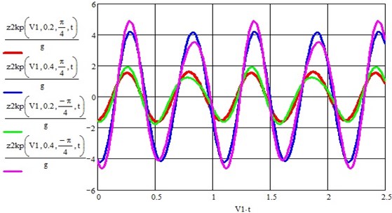
Fig. 12Graph of the bouncing acceleration of the wheelset of the vehicle at a speed of 20 m/s for two coefficients of parametric perturbation 0.2 and 0.4 and two phase shift angles between the effects of 45° and –45° (the abscissa is the movement of the vehicle along the path in m)
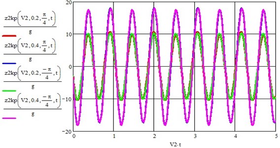
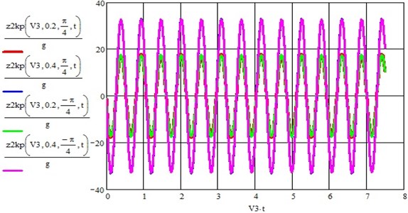
Fig. 13Graph of the bouncing acceleration of the wheelset of the vehicle at a speed of 30 m/s for two coefficients of parametric perturbation 0.2 and 0.4 and two phase shift angles between the effects of 45° and –45° (the abscissa is the movement of the vehicle along the path in m)
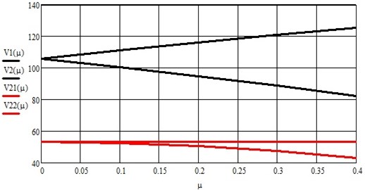
Finally, we present the main and second parametric resonance zones as a function of speed (km/h) of the parametric disturbance coefficient , which are shown in Fig. 14. They are both in the operating speed range of modern trains [11].
Fig. 14The main and second areas of dynamic instability of the wheel set of the vehicle
2. Conclusions
From the foregoing, the following conclusions can be drawn:
First, the parametric system in some sense resembles in its behavior a nonlinear system.
Secondly, the phase shift angle between the disturbances plays a significant role, because it either increases or decreases the amplitude of the wheelset bouncing oscillations.
Thirdly, the fundamental harmonic resonates at speeds from 10 to 27 m/s (from 36 km/h to 97.2 km/h), and the third harmonic resonates around 10 m/s (36 km/h).
Fourthly, the maximum amplitude of the bouncing of the wheelset from the longitudinal non-uniformity of the track is an order of magnitude higher than the same indicator from the geometrical roughness on the rail tread surface. Therefore, the uneven elasticity of the track must be taken into account in the calculation schemes of the rolling stock and their mathematical models. To combat resonant phenomena, the following methods can be applied: changing the parameters of the oscillatory system in order to divert the resonant frequency to the zone of non-operational modes and damping oscillations, which makes it possible to reduce the amplitude of oscillations of the resonant peak.
References
-
Nekhaev V. A., “Defining for RMS-velosity of rolling stock,” (in Russian), Journal of Transsib Railway Studies, Vol. 28, No. 4, pp. 11–23, 2016.
-
T. Schmidt, Parametric Oscillations. (in Russian), Moscow: Mir, 1978.
-
A. Karassayeva et al., “Analysis of dynamic properties and movement safety of bogies with diagonal links and rubber-metal vibration absorbers between the rubbing elements of freight cars,” Journal of Machine Engineering, Vol. 21, No. 3, pp. 124–143, Sep. 2021, https://doi.org/10.36897/jme/141926
-
M. Murzakayeva, J. Musayev, M. Kvashnin, S. Zhunisbekov, A. Zhauyt, and M. Azilkiyasheva, “Experimental evaluation of railway crew impact on tension rails,” International Journal of Mechanical Engineering and Robotics Research, Vol. 10, No. 5, pp. 261–269, 2021, https://doi.org/10.18178/ijmerr.10.5.261-269
-
J. Musayev, Y. Yelzhanov, M. Aliyarova, A. Yelemanova, and A. Zhauyt, “Shock-impulse diagnosis of railway,” 17th International Scientific Conference Engineering for Rural Development, Vol. 17, pp. 1618–1623, May 2018, https://doi.org/10.22616/erdev2018.17.n551
-
V. Solonenko, N. Mahmetova, J. Musayev, M. Kvashnin, A. Alpeisov, and A. Zhauyt, “Some aspects of the experimental assessment of dynamic behavior of the railway track,” Journal of Theoretical and Applied Mechanics, Vol. 55, No. 2, p. 421, Apr. 2017, https://doi.org/10.15632/jtam-pl.55.2.421
-
I. C. Cruceanu and Sorohan, “Determination of the harmonic response of a railway wheelset using the finite element analysis method,” Procedia Manufacturing, Vol. 46, pp. 173–179, 2020, https://doi.org/10.1016/j.promfg.2020.03.026
-
T. Mazilu and M. A. Gheti, “On the bending vibration of a train driving wheelset,” in IOP Conference Series: Materials Science and Engineering, Vol. 591, No. 1, p. 012059, Aug. 2019, https://doi.org/10.1088/1757-899x/591/1/012059
-
V. Solonenko, N. Mahmetova, J. Musayev, M. Kuashnin, A. Zhauyt, and T. Buzauova, “Modeling of dynamic characteristics of freight car withoptimized parameters of wedge-type shock absorber,” Journal of Vibroengineering, Vol. 19, No. 2, pp. 1197–1213, Mar. 2017, https://doi.org/10.21595/jve.2017.16901
-
J. Musayev, A. Zhauyt, M. Sagatbek, N. Matikhan, Y. Kaliyev, and B. Naurushev, “Seismic resistance of horizontal underground openings in anisotropic rocks,” Vibroengineering Procedia, Vol. 8, pp. 231–236, Oct. 2016.
-
K. Szabelski and J. Warmiński, “Parametric self-excited non-linear system vibrations analysis with inertial excitation,” International Journal of Non-Linear Mechanics, Vol. 30, No. 2, pp. 179–189, Mar. 1995, https://doi.org/10.1016/0020-7462(94)00037-b
About this article

The authors have not disclosed any funding.
The datasets generated during and/or analyzed during the current study are available from the corresponding author on reasonable request.
The authors declare that they have no conflict of interest.
