Abstract
High-speed railways often run over underground metro stations. Dynamic load induced by high-speed train can influence the internal force of underground structure and hence can pose danger to the underground structure. Hence, it is necessary to estimate the safety of underground structure due to high-speed train load. In this paper, the effects of dynamic load induced by high-speed train on metro station are investigated by carrying out three-dimensional numerical analysis. Guinan high-speed railway, which is designed to run over Jinqiao metro station in Nanning, Guangxi province of China are adopted as the background of this case study. The hardening soil model with small-strain stiffness was adopted to model the behaviour of soil. Two typical speed of railway train (i.e., 160 km/h and 350 km/h) are considered in this study. Based on the numerical analysis, vertical vibration acceleration and bending moment of the structure of the metro station are presented and analysed.
1. Introduction
High-speed railways are developed rapidly for its high transportation efficiency in recent years, especially in China. Sometimes, high-speed railways run over underground metro stations. Dynamic load induced by high-speed train can influence the internal force of underground structure and hence can pose danger to the underground structure. Estimation of effects of dynamic load induced by high-speed train on underground structures is a major challenge for designers and engineers.
The response of underground structure induced by dynamic load due to high-speed train has been reported by many researchers. Jones and Block [1] proposed a method for the prediction of vibration induced by train. Feng et al. [2] reported anin-situ high-speed train generated ground vibrations were measured in the embankment, culvert, viaduct and transition sections of Beijing-Shanghai high speed railway (HSR) in China. They found the amplification zone was around 20 m due to the wave interference. Xiao et al. [3] proposed an analysis method to estimate the settlement deformation of engineered structures under the tracks of high-speed railway lines. Liu [4] investigated the effects of dynamic load induced by railway train on tunnel structure by carrying out numerical analysis. The effects of cover depth of tunnel and speed of train were investigated. The vertical displacement and dynamic response induced tunnel structures were reported.
Although the effects of dynamic load due to high-speed railway on the underground structure have been investigated by a lot of researchers, three-dimensional numerical analysis of the effects of dynamic load on underground structure are rarely reported. In addition, it is well recognized that the stiffness of most soil decreases with increase of strain and depends on the recent stress and strain history of the soil [5]. In order to obtain a satisfactory numerical model on estimating the soil deformation, it is necessary to take account of the small strain stiffness of soil instead of using a simple model with constant soil stiffness. In this study, Guinan high-speed railway run over Jinqiao metro station of Nanning metro line 5, Guangxi province of China are adopted as the engineering background. A soil model considering the small strain stiffness of soil (HSS) are adopted in this study. In order to model the initial stress state of soil as well as the internal force of the underground structure before applying the dynamic load, three-dimensional numerical analysis was carried out considering the excavation procedure in the site. Two typical speed of railway train (i.e., 160 km/h and 350 km/h) are considered in this study. Based on the numerical analysis, vertical vibration acceleration and bending moment of the structure of the metro station are presented and analyzed.
2. Site introduction and numerical modelling
2.1. Site introduction
Fig. 1(a) shows the plan view and elevation view of the site for Jinqiao Station. The Jinqiao Station of Nanning metro line 5 were constructed using cut and cover method. This station has a long and narrow shape. The length and width of the excavation are 597.3 m and 19.2 m, respectively. The excavation depth of partrange from 18.2 to 20.7 m. Bore pile was adopted as the retaining structure for the excavation. The diameter and spacing of the bore pile is 1.2 m and 1.4 m, respectively. The length of the pile is 25 m. Jet grouting pile was used for the purpose of waterproof. Three layers of strut were designed inside of the excavation. The first layer of struts is concrete strut, while the struts for the rest two layers are steel strut. The arrangement and the dimension of the struts is shown in Fig. 1(b).
The first layer of soil in this site is fill with a thickness of about 6 m. The second the layer of soil is also fill with different parameters from the first layer. Below the two layers of fill, there is a thin layer of clay with a thickness of 2 m. Clay stone lays below the clay. The parameters of the soil can be referred to Table 1.
Fig. 1Schematic diagram of the site of Jinqiao Station
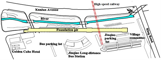
a) Plan view
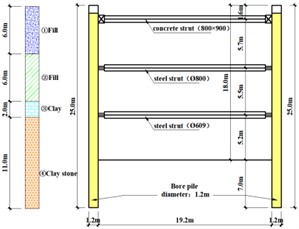
b) Elevation view
2.2. Finite element mesh and boundary conditions
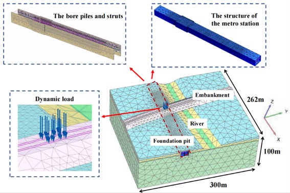
Fig. 2 shows the three-dimensional finite element mesh for the numerical analyses. The geometry of the mesh was the same as that in the site. Roller supports were applied on all vertical sides of the mesh and pinned supports were assigned to the base of the mesh. The total length of the model is 300 m and the width of the model is 262 m. The model has a depth of 100 m. In total, this model contains 109687 elements and 150794 nodes. The bore pile was modeled as a thick with an equivalent thickness of 0.623 m. The structure of the metro station was modeled using plate element considering the interaction with the retaining structure (i.e., bore pile). The struts are modelled using beam elements. The embankment and the dynamic load were modelled according the design document. The parameters of soil were adopted according to the geotechnical investigation report of this site.
Table 1Mechanical parameters of soil layers
No. | Soil layer | Thickness, m | Density, kN/m3 | C, kPa | , ° | , MPa | , MPa | , MPa | , 10-3 |
① | Fill_1 | 6.0 | 19.0 | 8 | 5 | 6 | 6 | 18 | 0.11 |
② | Fill_2 | 6.0 | 20.2 | 15 | 12 | 8 | 8 | 24 | 0.11 |
③ | Clay | 2.0 | 20.3 | 33 | 18 | 7.4 | 7.4 | 22.2 | 0.11 |
④ | Claystone | 86.0 | 21.1 | 65 | 18 | 50 | 50 | 300 | 0.11 |
Fig. 2Three-dimensional numerical model
2.3. Constitutive model and model parameters
It is known that the small strain stiffness is of great significant for the excavation-induced deformation problems [6]. In this study, the hardening soil model with small-strain stiffness was adopted forfill, clay and clay claystone. The numerical parameters are adopted based on the geotechnical investigation report. According to Plaxis manual [7], the reloading modulus, Eur, is taken as three times of the secant modulus, E50 for fill, clay and clayclaystone. For fill, clay and claystone, Eur is adopted as six times of the E50. The soil parameters used in this study are summarized in Table 1. The bore piles, struts and structure of metro station are modelled as linear elastic materials. The elastic modulus of concrete and steel are adopted as 30 GPa and 200 GPa, respectively.
2.4. Numerical modelling procedures
Table 2 shows the numerical modelling procedure of this study. The numerical modelling procedure follows the construction procedures of this site. In order to model the initial stress state of the model, the construction process of the excavation was considered. The excavation was divided into three steps. Struts are installed after each excavation steps. The ground water level is assumed to be 0.5m below the formation level.
3. Analysis of numerical results
3.1. Vibration force induced by high-speed train
Fig. 3(a) shows the vibration force induced by high-speed train under a speed of 160 km/h. According to Liang and Cai [8], the vibration force can be calculated using the following equation:
where is static load of train wheels, is vibration load of a typical value under stable state, is vibration load of a typical value under the control condition according to the dynamic additional load acting on the line, is vibration load of a typical value under waveform abrasion control, is circular frequency of rough vibration wavelength under three control conditions at corresponding vehicle speed. And the calculation formula of is , where, is the unsprung mass of the train, and the value is 750 kg, the is the typical vector height under the three control conditions of corresponding vehicle speed. The calculation formula of is , where, is the train running speed, and is the typical wavelength under the three control conditions.
Table 2Construction sequences
Steps | Construction sequences |
0 | Set initial stress state |
1 | Construction of bore pile and jet grout pile |
2 | Excavation of the first layer of soil and installation of the first strut |
3 | Excavation of the second layer of soil and installation of the second strut |
4 | Excavation of the third layer of soil and Installation of the third strut |
5 | Excavation of the fourth layer of soil |
6 | Construction of internal structure of metro station |
7 | Construction of high-speed railway embankment |
8 | Apply of dynamic load of high-speed train |
A time span of 0.5S are adopted in this study. As shown in Fig. 3(a), the maximum vibration force is 115 kN, while the minimum vibration force is 89 kN. The average vibration force is 102 kN. Fig. 3(b) shows the vibration force induced by high-speed train under a speed of 350 km/h. A time span of 0.5S are also adopted. The maximum vibration force is 164 kN, which is 42.6 % larger than that under a speed of 160 km/h. Meanwhile, and the minimum vibration force is 40 kN, which is 55.1 % smaller than that under a speed of 160 km/h. The average vibration force is also 102 kN, which is equal to that under a speed of 160 km/h.
Fig. 3Vibration force induced by high-speed train
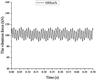
a) Under a speed of 160 km/h
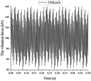
b) Under a speed of 350 km/h
3.2. Vertical vibration acceleration along depth
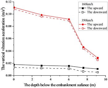
Fig. 4 shows the vertical vibration acceleration along the depth below the ground surface. The upward vibration acceleration and the downward vibration acceleration both decrease with the increase of depth below the embankment surface. In addition, the decreasing rate of the vertical vibration acceleration increased significantly when the depth is larger than 6 m under a speed of 350 km/h. The trend of the downward vibration acceleration is similar to the upward vibration acceleration. However, the value of the downward vibration acceleration is about 20 % lower than the upward vibration acceleration. The trend of curve for a train speed of 350 km/h is similar to that under a speed of 160 km/h, but the magnitude of the vibration acceleration is significantly larger.
Fig. 4Vertical vibration acceleration along depth
3.3. Bending moment of metro station
Fig. 5(a) shows bending moment of top slab, middle slab and bottom slab under a train speed of 160 km/h. The maximum bending moment of top slab occurs at the portion with a larger width (please refer to Fig. 1). This may indicate that the geometry arrangement of the underground structure can influence the bending moment of structure induce by dynamic load. The maximum positive and negative bending moment are 793.0 kN·m/m and –885.9 kN·m/m, respectively. Compared to the top slab, the bending moment of middle slab and bottom slab are negligible. This may be because the top slab is closer to the dynamic load.
Fig. 5(b) shows bending moment of top slab, middle slab and bottom slab under a train speed of 350 km/h. The distribution of bending moment of top slab, middle slab and bottom slab is similar to that under a train speed of 160 km/h. In addition, the magnitude of the bending moment is also close to that under a train speed of 160 km/h. The maximum positive and negative bending moment are 795.2 kN·m/m and –888.2 kN·m/m, respectively. It seems the speed of train has an insignificant influence on bending moment of top slab, middle slab and bottom slab.
Fig. 5Bending moment (M11) of top slab, middle slab and bottom slab
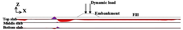
a) Under a speed of 160 km/h
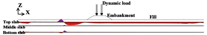
b) Under a speed of 350 km/h
Fig. 6(a) shows bending moment of side wall and middle wall under a train speed of 160 km/h. The maximum bending moment occurs at the middle wall. This may be related to the arrangement of structure of metro station. The maximum positive and negative bending moment are 127.2 kN·m/m and –87.04 kN·m/m, respectively.
Fig. 6(b) shows bending moment of side wall and middle wall under a train speed of 350 km/h. Generally, the bending moment of side wall and middle wall under a train speed of 350 km/h is larger than that under a train speed of 160 km/h. This means the speed of train has a significant influence on bending moment of side wall and middle wall. This is different with the bending moment for top slab, middle slab and bottom slab. The maximum positive and negative bending moment are 136.3 kN·m/m and –148.2 kN·m/m, respectively. Both the maximum bending moment induced in the structure of metro station is within the structure capacity of the structure.
Fig. 6Bending moment (M11) of side wall and middle wall
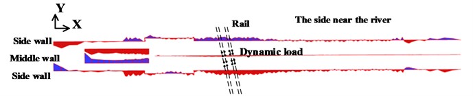
a) Under a speed of 160 km/h
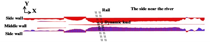
b) Under a speed of 350 km/h
4. Conclusions
In this paper, the effects of dynamic load induced by high-speed train on metro station are investigated by carrying out three-dimensional numerical analysis. The hardening soil model with small-strain stiffness was adopted to model the behavior of soil. Two typical speed of railway train (i.e., 160 km/h and 350 km/h) are considered in this study. Based on the numerical analysis, the following conclusions can be drawn:
1) The vertical vibration acceleration along the depth below the ground surface decrease with the increase of depth below the embankment surface. The trend of the downward vibration acceleration is similar to the upward vibration acceleration. The amplitude of vibration acceleration under a train speed of 350 km/h is significantly larger than that at 160 km/h.
2) The dynamic load due to high-speed train in top slab is larger than that in middle slab and bottom slab. The maximum bending moment induced in top slab is 885.9 kN·m/m. The maximum bending moment induced inside wall is 148.2 kN·m/m. Both the maximum bending moment induced in the structure of metro station is within the structure capacity of the structure.
References
-
C. J. C. Jones and J. R. Block, “Prediction of ground vibration from freight trains,” Journal of Sound and Vibration, Vol. 193, No. 1, pp. 205–213, May 1996, https://doi.org/10.1006/jsvi.1996.0260
-
S.-J. Feng, X.-L. Zhang, L. Wang, Q.-T. Zheng, F.-L. Du, and Z.-L. Wang, “In situ experimental study on high speed train induced ground vibrations with the ballast-less track,” Soil Dynamics and Earthquake Engineering, Vol. 102, pp. 195–214, Nov. 2017, https://doi.org/10.1016/j.soildyn.2017.09.001
-
S. G. Xiao, Q. R. Yan, and W. Chen, “Characteristics of settlement and assessment methods of engineered structures under certain high-speed railway tracks in China,” Advanced Materials Research, Vol. 446-449, pp. 1869–1879, Jan. 2012, https://doi.org/10.4028/www.scientific.net/amr.446-449.1869
-
K. Liu, “Study on dynamic response of tunnel structure in early age stage under dynamic load of upper railway,” (in Chinese), Ph.D. Thesis, Southwest Jiaotong University, 2019.
-
J. H. Atkinson, D. Richardson, and S. E. Stallebrass, “Effect of recent stress history on the stiffness of overconsolidated soil,” Géotechnique, Vol. 40, No. 4, pp. 531–540, Dec. 1990, https://doi.org/10.1680/geot.1990.40.4.531
-
T. Benz, “Small-strain stiffness of soils and its numerical consequences,” Ph.D. Thesis, University of Stuttgart. Stuttgart, 2006.
-
“PLAXIS 3D material models manual,” Plaxis, Delft, the Netherlands, 2016.
-
B. Liang and Y. Cai, “Dynamic analysis on subgrade of high speed railways in geometric irregular condition,” (in Chinese), Journal of the Chinese Railway Society, Vol. 21, No. 2, 1999.
About this article

The authors have not disclosed any funding.
The datasets generated during and/or analyzed during the current study are available from the corresponding author on reasonable request.
The authors declare that they have no conflict of interest.
