Abstract
The unintended vibrations and sound emerging from train operation have an enormous impact on the surroundings, including the deterioration of the way, buildings, and structures. One proposed strategy to mitigate this issue is the installation of a rail pad inserted between the steel rail and concrete sleeper to provide flexibility to the track and cushion the shocks and vibrations generated by the train wheels’ movement. These materials have nonlinear, dissipative properties influenced by service conditions like temperature and toe load. This work aimed to investigate the static stiffness of different materials of the rail pad under the influence of temperature and toe load. The rail pads were categorized as soft, medium, or hard based on static stiffness. A 3D model of the rail pad, steel rail, and concrete sleeper was simulated and analyzed using ANSYS FEM software. The neo-Hookean model was used to model the rail pad, and the isotropic elasticity model was used for the steel rail and concrete sleeper. The static stiffness of the ethylene propylene diene monomer (EPDM) pad was 85.42 kN/mm, lower than that of thermoplastic elastomers (TPEs, 138.98 kN/mm) and ethylene vinyl acetate (EVA, 303.70 kN/mm) under reference conditions (20 °C), without including toe load effects. Increasing the temperature decreased the rail pad’s static stiffness, with the highest reduction of 53.49 %. However, increasing the toe load contributed up to a 23.53 % increase in the static stiffness of the rail pad.
1. Introduction
The health and long-term performance of infrastructure are critical in any rail system, not only for safety reasons but due to the high maintenance costs involved. Furthermore, given the social and economic ramifications, any disruption in railway service must be minimized. The optimization of track condition is one of the main components for smooth and good service in railway systems.
The rail fastening system is an essential component of the rails, enabling them to operate in their original form [1]. One of the important parts of the fastening system is the rail pad [2]-[5], which is placed beneath the rail [6]-[8]. One of the functions of the rail pad is to protect the sleeper [9]-[11]. Furthermore, the rail pad improves protection for the ballast under higher dynamic overloads [12]-[14]. The main function of the rail pad is to supply ample vertical stiffness for both ballasted track and slab track [15]-[17].
Rail pad stiffness has a greater influence on track operation for slab track than for ballasted track [18]-[20]. The vertical stiffness of the rail pad is critical for track performance, maintenance, and durability [4], [21]-[23]. The high stiffness of the track contributes to the increase of the transfer of load to slab track, destroying the concrete slab and leading to track irregularity. On the other hand, with the low stiffness of the track, the lateral displacement of the railhead increases, increasing the likelihood of gauge-widening derailment and the operation price due to the increased amount of electricity needed to operate the train [24].
Toe load is defined as the compressive force on the rail pad that holds the rail in the position and is applied by the fastening system [20]. The toe load has a reference value of around 18 kN [21]. However, this value can vary because of excessive or insufficient torque during fastening/tightening or because of sheath creep. In the worst-case scenario, the fastening will break, resulting in the absence of the toe load. The absence of the rail clip’s toe load could allow rail sleeper movement, causing significant damage to the rail pad. The rail pad must be mechanically characterized at a temperature of 23±5 °C according to European standards EN 13481-2 and EN 13146-9. In addition, it should be noted that, as a result of climate change, both average and (especially) extreme temperatures of rail service is gradually rising [21].
The analysis of the rail pad condition has attracted the attention of many researchers. Several authors have dedicated their research to experimental work investigating the mechanical characteristics of rail pads. Experimental work by Zhu et al. and Wei et al. concluded that the stiffness of the rail pad increased with load frequency [22], [25]. Wei et al. mentioned that the vertical stiffness of TPE rail pads was directly proportional to the load amplitude [26]. In addition, Zhu et al. found that increased load frequency triggered the growth of both hysteresis and stiffness [27]. Fenander discovered that the stiffness of rail pads increased significantly with preload, and increased more moderately with frequency [28]. However, studies by Wei et al. found that stiffness decreased with temperature [25], [29].
Other authors have applied numerical methods to predict nonlinear mechanical rail pad behavior. Zhang et al. developed a finite element (FE) model of the fastening system which included the rail, sleeper, rail pad, rail clip, shoulder, and insulator [1]. They studied the effect of preload on fastening system performance. Koroma et al. modeled the rail pad using FE subjected to static and dynamic loading [30]; they suggested that the nonlinearity of rail pad and preload affected the track vibration. Oregui et al. used linear spring/dashpot elements to simulate railway tracks that included a rail pad, clip, and ballast [31]. The study used an impact hammer as applied loading to investigate the effect of preload and stiffness properties towards the dynamic stiffness of the track. Yang et al. showed that the nonlinear condition of the fastening system changed the railway bridge vibration [32]. Liu et al. applied FE to investigate the effect of nonlinearity on the mechanical characteristics of the fastening system [33].
Researchers have also used linear spring/dashpot elements to model vehicle–track interaction [22], [34]-[39]. Most numerical studies have proved that the vertical behavior of fastening systems is nonlinear. However, the prediction of appropriate mechanical characterization focusing on very specific material and working conditions has not been well studied.
In this study, the characterization of static stiffness for different materials of rail pads (i.e., ethylene propylene diene monomer (EPDM), thermoplastic elastomers (TPEs), and ethylene vinyl acetate (EVA)) under the influence of temperature and toe load was predicted using FE analysis. Next, this paper classifies the rail pad as soft, medium, or hard based on static stiffness behavior. A three-dimensional (3D) FE model was used to represent the fastening system.
For design solutions, the laboratory and field study were constrained in terms of timeframe and cost. Therefore, the finite element method (FEM) approach was developed to perform a rapid analysis of the influence of critical variables. We believe that the developed model can serve as a tool for estimating the behavior of rail pad static stiffness under different parametric conditions. This approach can also be used as a decision-support tool for the implementation of maintenance strategies.
2. Materials and methods
2.1. Mathematical modeling
The elastic deformation must be considered to calculate the static stiffness of the rail pad. Elastic deformation () can be calculated by using:
where is the normal stress, is the modulus of elasticity, is the force, is the length, and is the area.
The modulus of elasticity can be calculated by using:
where is the strain.
Normal stress () can be calculated using:
where is the normal force and is the area.
As the elastic deformation of the rail pad has been identified, the static stiffness () is the ratio between the load range and the displacement range during the last load ramp. It can be calculated using the formula:
2.2. Simulation test campaign
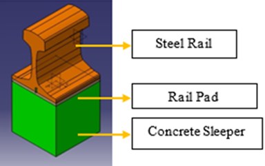
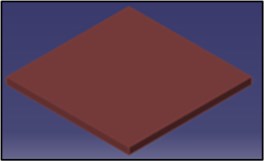
The geometry of the steel rail, rail pad, and concrete sleeper was modeled using CATIA V5 software. The steel rail was modeled following the International Union of Railways (UIC) standards. Fig. 1 shows the isometric view of the steel rail, rail pad, concrete sleeper, and rail pad geometry.
Fig. 1Isometric view of the: a) fastening system model; b) rail pad dimensions.
a)
b)
The 3D model of the fastening system was then imported to the ANSYS software for simulation and analysis. The influence of the temperature and toe load on the static stiffness of the most used rail pads (made of EPDM, TPEs, and EVA) were determined. The standard value for the toe load was 18 kN. There were four cases of the toe load. First, the scenario corresponding to the system’s proper assembly, which was 18 kN. Then, an extreme scenario of 1 kN, indicating the deterioration of the fastening system. Lastly, two additional criteria were examined based on the fastening system’s potential under-torque or over-torque, which were equal to 9 kN and 25 kN, respectively. These were evaluated to show the effects of toe load over-tightening or under-tightening.
The simulation was carried out with different temperatures, starting from the standards room temperature (23±5 °C). By considering the situation in Malaysia, the test was conducted at the maximum temperature of 60 °C and the minimum temperature of 0 °C. The highest temperature in Malaysia was recorded at 40.1 °C; however, because of the heating caused by the repeating cycle of the wheels passing along the railway, the rail pad’s temperature could reach the maximum temperature of 60 °C. Additionally, to use similar temperature intervals, five different temperatures between the extremes (10 °C, 20 °C, 30 °C, 40 °C, and 50 °C) were included.
2.3. Material properties
2.3.1. Rail pad
The rail pads were modeled using a solid element with nominal cross-sectional geometry. EPDM, TPE, and EVA are materials with rubber-like properties. Rubber-like materials are hyperelastic materials that produce a nonlinear behavior. For this reason, the neo-Hookean formula was used to analyze the elastomer behavior.
The neo-Hookean model is a simple hyperelastic model that depends on two material parameters: bulk modulus, , and shear modulus, . These two material parameters are derived from Young’s modulus, , and Poisson’s ratio, . The neo-Hookean theory was used in FE analysis to compute both compressible and incompressible deformation conditions. In this study, for an arbitrary deformation condition, the compressible neo-Hookean model was used. The following expression shows the so-called Cauchy stress [40]:
where is the bulk modulus, is the shear modulus, is a Jacobian determinant, is a left Cauchy–Green deformation tensor, and is a unity tensor. The length, width and thickness ( × × ) of the rail pad is 150 mm, 150 mm and 8 mm respectively.
2.3.2. Steel rail and concrete sleeper
The steel rail and concrete sleeper were modeled by a solid element with nominal cross-sectional geometry. For solid materials such as concrete and steel, linear elasticity is the standard way to model the minor strain mechanical behavior [41], [42], [43]. Furthermore, isotropic elasticity is the simplest form of the theory of elasticity. The stress in this version of the idea is proportional to the applied pressure and independent of the material body’s orientation. Table 1 shows the properties and attenuation parameters of the track structures. The values were collected from various scientific publications and standard properties of the materials from the web.
2.4. Boundary conditions and load
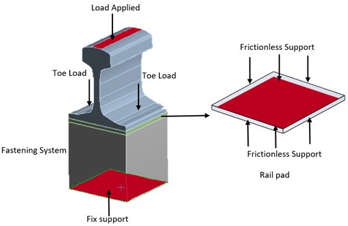
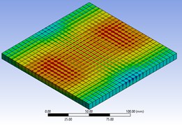
Fig. 2 shows the applied load, toe load, and boundary conditions applied to the fastening model. The applied load is the forces applied by the wheels from the rails. The load was applied incrementally. At each step, the rail pad deformation was computed. Boundary conditions were used in the 3D model analysis to replace the support in the experiment. The fixed support was applied on the bottom surface of the concrete sleeper. Frictionless support was used on the four sides of the rail pad and on the two sides of the rail. The frictionless support provided support for the geometries in an average direction. The geometries were prevented from moving in a moderate direction but freely rotated or moved in a tangential direction.
The contact location between parts was defined for appropriate simulation results. The contact between the rail and concrete sleeper with the rail pad was defined as frictional contact, with the friction coefficient of 0.14. In this frictional contact, before two types of geometries start sliding relative to each other, they can carry shear stresses of a certain magnitude across their interface. This phenomenon is known as “sticking.”
Table 1Basic properties of rail pads, steel rail, and concrete sleeper structures
Rail pad track structure | Density, (kgm-3) | Coefficient of Thermal Expansion, , C-1 | Young’s modulus, , MPa | Poisson’s Ratio, | Tensile Yield Strength, , MPa | Tensile Ultimate Strength, MPa | Initial Shear modulus Mu, GPa | Incompressibility parameter , K Pa- |
EPDM | 2000 | 0.000165 | 11.2 | 0.43 | 5.5 | 25 | 3916000 | 7.5-8 |
TPE | 1300 | 0.00013 | 30 | 0.41 | 34.5 | 52 | 10638000 | 3.6-8 |
EVA | 940 | 0.00016 | 40 | 0.49 | 30 | 40 | 13423000 | 3-9 |
Type of track structure | Density, (kgm-3) | Coefficient of Thermal Expansion, , C-1 | Young’s Modulus, , MPa | Poisson’s Ratio, | Tensile Yield Strength, , MPa | Compressive Yield Strength, MPa | Tensile Ultimate Strength, , MPa | Compressive ultimate strength , MPa |
Structural Steel (rail) | 7850 | 0.000012 | 200000 | 0.3 | 250 | 250 | 460 | 0 |
Concrete (sleeper) | 2300 | 0.000014 | 30000 | 0.18 | 0 | 0 | 5 | 41 |
Fig. 2Loads applied and supported in the model
2.5. Meshing
The FE model was defined in the form of nodes representing size and location. The elements selected in this simulation were three-dimensional solid elements. Square parts were more suitable to model the bending that prevails. Due to the complex-shaped model, a three-dimensional cuboidal feature with a triangular base was introduced, as shown in Fig. 3. This configuration better represents stress concentration and allows for a better approximation of curved shapes with fewer elements.
Fig. 3Cuboidal element (C3D8R) with a triangular element (C3D6)

A mesh convergence test was conducted to ensure accurate simulation results. An inaccurate simulation result often occurs if the mesh becomes too coarse. Furthermore, as the mesh refinement increases, the time for computing resources to run a simulation also increases.
Table 2 shows the parameters for the mesh setting considered in this study. From the table, it can be observed that the total deformation was inversely proportional to the number of elements. As the number of elements decreased, the total deformation also changed until it reached a plateau value of 1.28 mm. Furthermore, the time for the simulation to generate the results decreased as the number of elements decreased. The simulations with 25785 and 32887 elements showed similar values with the validation research paper [21], but less time was required for the simulation to generate the results when 25785 elements were used in comparison to the simulation with 32887 elements. Hence, 25785 elements were used in the current study for further simulation.
Table 2Mesh setting parameters
Element size (mm) | Nodes | Elements | Time consumption (minutes) | Total deformation at 90 kN (mm) |
5.0 | 177163 | 39557 | 248 | 1.24 |
5.4 | 148391 | 32887 | 198 | 1.27 |
5.8 | 117544 | 25785 | 133 | 1.27 |
6.2 | 94678 | 20550 | 102 | 1.28 |
6.8 | 76640 | 16388 | 46 | 1.28 |
7.0 | 69221 | 14762 | 45 | 1.28 |
7.4 | 59777 | 12609 | 13 | 1.28 |
3. Results and discussion
3.1. Validation of simulation
The validation was performed with experimental data from a previous research paper to justify the accuracy of the simulation. Similar boundary conditions and load were applied in the simulation. Fig. 4 shows that the simulation data were in agreement with experimental data from Sainz-Aja et al. [21].
Fig. 4Comparison between simulation results with the experimental results in [21]
![Comparison between simulation results with the experimental results in [21]](https://static-01.extrica.com/articles/22293/22293-img5.jpg)
The simulation and previous experimental data are tabulated in Table 3 to determine the percentage error. The average value of percentage error was estimated to be 6.26 %. The percentage error needs to be below 10 % to consider the accuracy of the model simulation adequate. However, one or two percentage error values above 10 % is acceptable. The errors that occurred due to the experimental data were assumed to represent the authentic responses of the object under test with specific measuring errors such as device error and human error. On the other hand, the simulation data represent a theoretical model for the behavior of the same object.
Table 3Percentage error for simulation and experimental data
No. | Load (kN) | Deformation (mm) | Percentage error (%) | |
Reference | Simulation | |||
1 | 0 | 0.00 | 0.00 | 0.00 |
2 | 10 | 0.22 | 0.26 | 15.38 |
3 | 20 | 0.45 | 0.48 | 6.25 |
4 | 30 | 0.61 | 0.60 | 1.67 |
5 | 40 | 0.78 | 0.71 | 9.86 |
6 | 50 | 0.92 | 0.83 | 10.84 |
7 | 60 | 1.02 | 0.94 | 8.51 |
8 | 70 | 1.12 | 1.05 | 6.67 |
9 | 80 | 1.19 | 1.16 | 2.59 |
10 | 90 | 1.26 | 1.27 | 0.79 |
3.2. Static stiffness evaluation
3.2.1. Effect on temperature
Fig. 5 shows the static load deformation for three types of rail pad under reference conditions. The nonlinear deformation of the rubber-type materials was observed as load increased for each type of material. The compressive force increased the displacement of the rail pad nonlinearly. These results are in line with previous studies [44], [28]. The EPDM pad showed more deformation than the other two rail pads with similar applied load. All three rail pads showed different stiffening conditions. Above 20 kN, the EPDM pad displayed a necessary stiffening. The least deformable rail pad was the EVA pad, and the deformation was concentrated more in the initial region, up to 40 kN. The TPE pad’s behavior was intermediate between EPDM and EVA pads and showed slight stiffening. These findings are compatible with the data obtained by other researchers [21].
Fig. 5Load-deformation curve of three materials under reference conditions (20 °C)
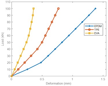
In general, the deformation of the rail pads was inversely proportional to the modulus of elasticity. The higher the modulus of elasticity, the lower the deformation of the rail pads. The modulus of elasticity for the EPDM pad was the lowest compared to TPE and EVA pads, as shown in Table 1.
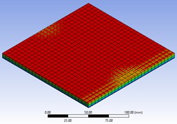
During operation, the temperature of rail pads changes constantly. The effect of temperature on the load-deformation curve for each rail pad is shown in Fig. 7. In general, the deformation of the rail pads increased as the temperature increased. This in line with the results of Xu et al. [45] and Liu et al. [46]. From the observation, deformation of the EVA material increased gradually as temperature increased over the entire range of 0-60 °C. Comparing the deformation at the highest load between 0 and 60 °C, the EVA was the most affected by temperature, with a 104.69 % increase in deformation at the higher temperature. The temperature dependence of deformation of TPE and EPDM was similar, with respective increases of 28.94 % and 17.31 % in deformation at the higher temperature. Fig. 6 shows the simulation results of the deformation of the three pads at the maximum and minimum temperatures. The deformation of each pad can be observed through the intensity of red color on the pad. The deformation of the EVA pad was most significant compared to the other two pads. The results show that the temperature changed the volume of each rail pad due to thermal expansion and contraction. However, for the polymer with high degree of cross-linking, the deformation was smaller. This is because polymers become more rigid as the degree of cross-linking increases [47].
Fig. 6The effect of temperature on deformation for all three rail pads
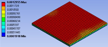
a) EPDM (0 °C)
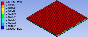
b) EPDM (60 °C)
c) TPE (0 °C)
d) TPE (60 °C)
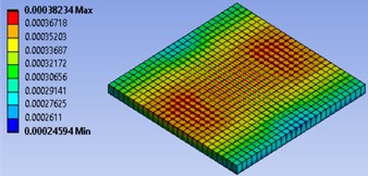
e) EVA (0 °C)
f) EVA (60 °C)
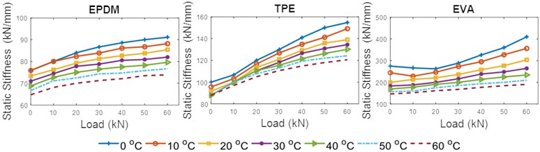
The static stiffness, as defined in Eq. (4), as a function of load is shown in Fig. 8. for each rail pad. Considering a toe load of 18 kN () and an increasing load range () each curve represents one tested temperature. The load range was in between 0-60 kN with the step 10 kN. As can be observed, the static stiffness increased as the loading increased. This is in line with the results in [48]. The stiffness of the EPDM pad was the lowest compared to TPE and EVA. The EPDM pad showed a constant trend of increasing stiffness with increasing load at all temperatures, while the TPE and EVA pads showed gradual stiffening as the load was applied at low temperatures. This result is correlated with the young modulus for each material, as shown in Table 1.
However, as temperature increased, the stiffness for the three materials dropped drastically. This is in agreement with the results reported by other researchers [49]. EVA rail pads experienced the highest drop in stiffness (53.49 %) as temperature increased at the highest load applied (60 kN). This is expected as deformation is inversely proportional to stiffness. Since the EVA pad experienced the largest deformation as temperature increased, it had the highest drop in stiffness. In TPE and EPDM pads the stiffness dropped by 22.05 % and 18.92 %, respectively. The stiffness for the EPDM pad trended towards a plateau at each temperature shifting as the load applied increased. On the other hand, for EVA and TPE pads, the stiffness showed a significant increasing trend for all temperatures as the load applied increased.
By increasing the temperature, the thermal atomic vibration increases. This increases the lattice potential energy and the curvature of the energy curve. Lattice energy is the energy required to split a mole of an ionic solid into gaseous ions. Thus, at high energy, the increasing molecular mobility causes the deformation of the rail pads to increase. This allows the rail pads to deform more easily at a microscopic level and reduces the modulus of elasticity. Even though the three rail pads’ stiffness decreased as the temperature increased, they exhibited distinct behaviors after being exposed to temperature changes. This was due to the different degrees of cross-linking conditions in the respective materials. At a higher degree of cross-linking, more energy is required for the molecules to freely mobilize. The cross-linking of polymers alters the deformability, and changes the modulus elasticity and stiffness [47].
Fig. 7Load-deformation curves of the three materials at different temperatures
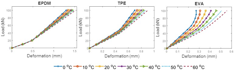
Fig. 8Static stiffness-load curves of the three materials at different temperatures
3.2.2. Effect on toe load
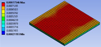
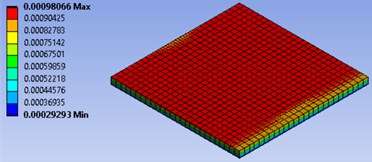
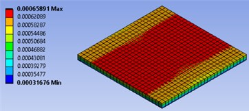
Fig. 10 shows the deformation of EPDM, TPE, and EVA pads under the effect of toe load. In general, increased toe load reduced the deformation and significantly exposed the nonlinear behavior of the materials. Similar findings have been observed in other studies [31]. At 90 kN applied load and reference conditions, the highest reduction of deformation was seen in the EPDM pad, with a reduction of 16.62 % as toe load increased from 1 to 25 kN. This was followed by the TPE and EVA pads, with deformation reductions of 15.07 % and 9.66 %, respectively. The effect of toe load on the deformation of the rail pads is shown in Fig. 9. The red areas show the expansion that occurred in the rail pads.
In practice, EPDM, TPE, and EVA perform like anisotropic materials with properties that are directionally dependent. Results show that the deformation of the three types of material increased as force increased but decreased as toe load increased. This is due to the change in the geometry of the materials as force is applied. The compressive force positioned the molecular chains more in the transverse direction. As higher force is applied, the degree of projection of a material inward or outward depends on the properties of the material. In this case, the compression from the toe load limited the expansion of the rail pad. The compressive force was substantial as toe load increased.
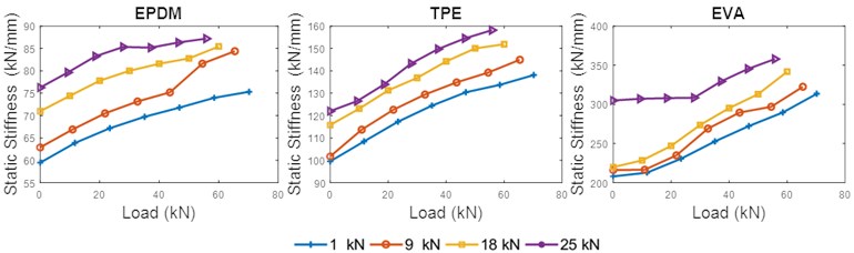
Reduction in deformation for the similarly applied load at the reference conditions contributed to increase the static stiffness, as shown in Fig. 11. It can be observed that for the three types of rail pads, the static stiffness increased as the toe load increased. The results obtained agree with previous work carried out in [21]. The curve profile for static stiffness indicates a significant effect of toe load throughout the entire load range analyzed. The highest increase of the static stiffness for 1-25 kN toe load at 55.80 kN loads was seen in the EVA pad, with a 23.53 % increase. This was followed by TPE and EPDM pads, with 18.26 % and 17.85 % increases in static stiffness, respectively. However, the EVA rail pad showed significant nonlinear material properties. While it demonstrated the lowest change in deformation, it had the greatest increase in static stiffness.
Fig. 9Simulation displays of the pads with the effect of 25 kN toe load under reference conditions (20 °C)
a) EPDM
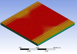
b) TPE
c) EVA
Fig. 10Load-deformation curves of three materials for different toe load (20 °C)
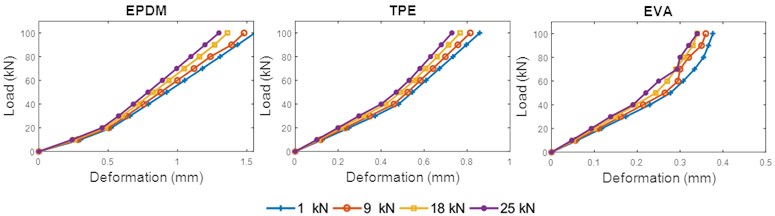
Fig. 11Static stiffness curve of three materials for different toe load (20 °C)
3.3. Rail pad classification
By following the European standards, a rail pad with stiffness less than 80 kN/mm is a soft rail pad, one with a stiffness between 80 and 150 kN/mm is a medium rail pad, and one with a stiffness greater than 150 kN/mm is a hard rail pad [50]. For high-speed tracks, the requirement of static stiffness is below 200 kN/mm, and a static stiffness above 200 kN/mm is suitable for industrial lines or heavy haul freight [51].
The stiffness of the EPDM pad under reference conditions (20 °C) without including toe load effects was recorded at 85.42 kN/mm; for the TPE pad it was 138.98 kN/mm, and it was 303.70 kN/mm for the EVA pad, as shown in Table 4. Hence, both EPDM and TPE pads could be considered medium pads. The EVA pad could be considered a hard pad. However, when the EPDM pad reached the temperature range of 40-60 °C, the rail pad characteristics moved to a soft pad condition. The TPE pad showed a hard pad condition at a temperature of 0 °C and medium pad condition for temperatures above that. The EVA pad had a high stiffness at 0 °C. This gradually decreased as temperature increased, but the pad maintained its hard pad condition.
This research showed that the TPE pad was the most favorable for use on high-speed track with wide range of temperatures compared to the EPDM pad. This is because the TPE pad maintained a medium pad condition at almost all temperatures except 0 °C. Furthermore, the use of the EPDM pad at temperatures between 40 and 60 °C might lead to fatigue in the fastening system. The EVA pad was most favorable for use in industrial lines or heavy haul freight tracks because the stiffness was greater than 200 kN for almost all temperatures, except 60 °C. However, at 0 °C, the EVA pad showed high stiffness, which could damage the track.
Table 4Maximum stiffness of rail pads with different temperatures
Temperature (°C) | Maximum rail pad stiffness (kN/mm) | ||
EPDM | TPE | EVA | |
0 | 91.11 | 154.75 | 410.00 |
10 | 88.17 | 149.09 | 356.52 |
20 | 85.42 | 138.98 | 303.70 |
30 | 82.00 | 134.43 | 264.52 |
40 | 79.61 | 130.16 | 234.29 |
50 | 76.64 | 124.24 | 210.26 |
60 | 73.87 | 120.59 | 190.70 |
Table 5 shows the stiffness of the rail pads subjected to the toe load. It can be observed that the EPDM produced a soft pad condition at a toe load of 1 kN and a medium pad condition at toe loads of 9 kN, 18 kN, and 25 kN. The TPE pad showed a medium pad condition at toe loads of 1 kN and 9 kN but became a hard pad at toe loads of 18 kN and 25 kN. The condition for the EVA pad was hard and gradually stiffened with increasing toe load.
The EPDM and TPE pads shared a similar result for the medium pad condition, but the TPE pad was still the most favorable to be inserted on high-speed track. This is because the TPE pad was stiffer than the EPDM pad. In addition, the EVA pad showed excellent properties for insertion on industrial line track because the stiffness of the rail pad exceeded 200 kN.
Table 5Maximum stiffness of rail pads with different toe loads under reference conditions (20 °C)
Toe load (kN) | Maximum rail pad stiffness (kN/mm) | ||
EPDM | TPE | EVA | |
1 | 75.32 | 138.10 | 313.51 |
9 | 84.38 | 144.93 | 322.50 |
18 | 85.42 | 151.85 | 341.67 |
25 | 87.18 | 158.14 | 357.89 |
4. Conclusions
The characterization of the fastening system is critical for rail vehicles and track systems. A 3D FE model was used to investigate the static stiffness of widely used rail pads: EPDM, TPE, and EVA. The practical variables examined were temperature and toe load. Based on the simulation results, the following conclusions can be drawn:
1) For the materials studied, an increase in temperature caused a decrease in static stiffness. In polymeric materials, this type of behavior was expected. By setting the other variables as fixed at reference standard values, stiffness differences were observed in EPDM, TPE, and EVA pads as temperature changed in the range 0-60 °C. The findings showed high sensitivity to thermal variation, especially in the TPE and EVA pads. However, the EPDM pad showed a thermostable behavior.
2) The toe load was directly proportional to the static stiffness. In addition, variations in static stiffness were strongly material dependent.
3) The classification of the rail pad based on soft, medium, and hard pad conditions strongly depended on the stiffness. We observed that the EVA pad produced a hard pad condition with increasing temperature and toe load, which is suitable for industrial lines or heavy haul freight track. However, the EPDM and TPE pads showed soft and medium pad conditions suitable for high-speed track. Still, the TPE pad was selected as the best option for high-speed track because it was stiffer than the EPDM pad.
In general, static stiffness has limited value in technical specifications and regulations. The dynamic stiffness is the best way to explain the responses of the fastening system under in-service conditions. Therefore, it is recommended to include the dynamic stiffness together in future research. Then, to forecast the long-term behavior of track systems, the implementation of a degradation model is essential. This model could aid in the development of decision-making tools to improve rail track performance optimization and maintenance operations, which in turn would reduce the cost and improve the life cycle of the infrastructure.
References
-
Z. Zhang, B. Andrawes, and R. E. J., “Parametric study on the distribution of longitudinal load in railway track under dynamic wheel loading using finite element analysis,” International Journal of Civil Engineering, Vol. 2, No. 5, pp. 13–27, May 2015, https://doi.org/10.14445/23488352/ijce-v2i5p106
-
X. Ge, L. Ling, X. Yuan, and K. Wang, “Effect of distributed support of rail pad on vertical vehicle-track interactions,” Construction and Building Materials, Vol. 262, p. 120607, Nov. 2020, https://doi.org/10.1016/j.conbuildmat.2020.120607
-
D. Ferreño et al., “Prediction of mechanical properties of rail pads under in-service conditions through machine learning algorithms,” Advances in Engineering Software, Vol. 151, p. 102927, Jan. 2021, https://doi.org/10.1016/j.advengsoft.2020.102927
-
I. A. Carrascal et al., “Experimental study of metal cushion pads for high speed railways,” Construction and Building Materials, Vol. 182, pp. 273–283, Sep. 2018, https://doi.org/10.1016/j.conbuildmat.2018.06.134
-
J.-Y. Choi, K.-Y. Lee, J.-S. Chung, and S.-H. Kim, “Rail pad corrosion effects on the dynamic behavior of direct fixation track systems in marine environments,” Applied Sciences, Vol. 10, No. 7, p. 2245, Mar. 2020, https://doi.org/10.3390/app10072245
-
M. Sol-Sánchez, F. Moreno-Navarro, and M. C. Rubio-Gámez, “The use of deconstructed tire rail pads in railroad tracks: Impact of pad thickness,” Materials and Design, Vol. 58, pp. 198–203, Jun. 2014, https://doi.org/10.1016/j.matdes.2014.01.062
-
K. Knothe, M. Yu, and H. Ilias, “Measurement and modelling of resilient rubber rail-pads,” System Dynamics and Long-Term Behaviour of Railway Vehicles, Track and Subgrade, pp. 265–274, 2003, https://doi.org/10.1007/978-3-540-45476-2_16
-
M. Sol-Sánchez, F. Moreno-Navarro, and M. C. Rubio-Gámez, “The use of elastic elements in railway tracks: A state of the art review,” Construction and Building Materials, Vol. 75, pp. 293–305, Jan. 2015, https://doi.org/10.1016/j.conbuildmat.2014.11.027
-
S. Kaewunruen, A. Aikawa, and A. M. Remennikov, “Vibration attenuation at rail joints through under sleeper pads,” Procedia Engineering, Vol. 189, pp. 193–198, 2017, https://doi.org/10.1016/j.proeng.2017.05.031
-
Z. Yuan, S. Zhu, X. Yuan, and W. Zhai, “Vibration-based damage detection of rail fastener clip using convolutional neural network: Experiment and simulation,” Engineering Failure Analysis, Vol. 119, p. 104906, Jan. 2021, https://doi.org/10.1016/j.engfailanal.2020.104906
-
N. Karpuschenko, D. Velichko, and A. Sevostyanov, “Effectiveness of intermediate rail fastenings on the railway sections of Siberia,” Transportation Research Procedia, Vol. 54, pp. 173–181, 2021, https://doi.org/10.1016/j.trpro.2021.02.062
-
M. Sol-Sánchez, F. Moreno-Navarro, and M. Rubio-Gámez, “The use of deconstructed tires as elastic elements in railway tracks,” Materials, Vol. 7, No. 8, pp. 5903–5919, Aug. 2014, https://doi.org/10.3390/ma7085903
-
J. Pombo and J. Ambrósio, “An alternative method to include track irregularities in railway vehicle dynamic analyses,” Nonlinear Dynamics, Vol. 68, No. 1-2, pp. 161–176, Apr. 2012, https://doi.org/10.1007/s11071-011-0212-2
-
C. Ngamkhanong, Q. Y. Ming, T. Li, and S. Kaewunruen, “Dynamic train-track interactions over railway track stiffness transition zones using baseplate fastening systems,” Engineering Failure Analysis, Vol. 118, p. 104866, Dec. 2020, https://doi.org/10.1016/j.engfailanal.2020.104866
-
J. Chen and Y. Zhou, “Dynamic vertical displacement for ballastless track-subgrade system under high-speed train moving loads,” Soil Dynamics and Earthquake Engineering, Vol. 129, p. 105911, Feb. 2020, https://doi.org/10.1016/j.soildyn.2019.105911
-
J. Sainz-Aja et al., “Self-compacting recycled aggregate concrete using out-of-service railway superstructure wastes,” Journal of Cleaner Production, Vol. 230, pp. 945–955, Sep. 2019, https://doi.org/10.1016/j.jclepro.2019.04.386
-
Z. Zeng, A. Ahmed Shuaibu, F. Liu, M. Ye, and W. Wang, “Experimental study on the vibration reduction characteristics of the ballasted track with rubber composite sleepers,” Construction and Building Materials, Vol. 262, p. 120766, Nov. 2020, https://doi.org/10.1016/j.conbuildmat.2020.120766
-
D. Sung and S. Chang, “Nonlinear behavior of rail fastening system on slab track at railway bridge ends: FEA and experimental study,” Engineering Structures, Vol. 195, pp. 84–95, Sep. 2019, https://doi.org/10.1016/j.engstruct.2019.05.098
-
T. Xin, Y. Ding, P. Wang, and L. Gao, “Application of rubber mats in transition zone between two different slab tracks in high-speed railway,” Construction and Building Materials, Vol. 243, p. 118219, May 2020, https://doi.org/10.1016/j.conbuildmat.2020.118219
-
L. Ling, W. Li, H. Shang, X. Xiao, Z. Wen, and X. Jin, “Experimental and numerical investigation of the effect of rail corrugation on the behaviour of rail fastenings,” Vehicle System Dynamics, Vol. 52, No. 9, pp. 1211–1231, Sep. 2014, https://doi.org/10.1080/00423114.2014.934844
-
J. A. Sainz-Aja, I. A. Carrascal, D. Ferreño, J. Pombo, J. A. Casado, and S. Diego, “Influence of the operational conditions on static and dynamic stiffness of rail pads,” Mechanics of Materials, Vol. 148, p. 103505, Sep. 2020, https://doi.org/10.1016/j.mechmat.2020.103505
-
S. Zhu, C. Cai, and P. D. Spanos, “A nonlinear and fractional derivative viscoelastic model for rail pads in the dynamic analysis of coupled vehicle-slab track systems,” Journal of Sound and Vibration, Vol. 335, pp. 304–320, Jan. 2015, https://doi.org/10.1016/j.jsv.2014.09.034
-
M. Oregui, A. Man, M. F. Woldekidan, Z. Li, and R. Dollevoet, “Obtaining railpad properties via dynamic mechanical analysis,” Journal of Sound and Vibration, Vol. 363, pp. 460–472, Feb. 2016, https://doi.org/10.1016/j.jsv.2015.11.009
-
D. Sung and S. Hong, “A simple method to assess replacement period of polyurethane railpad in urban railway,” Construction and Building Materials, Vol. 248, p. 118607, Jul. 2020, https://doi.org/10.1016/j.conbuildmat.2020.118607
-
K. Wei, Q. Yang, Y. Dou, F. Wang, and P. Wang, “Experimental investigation into temperature – and frequency-dependent dynamic properties of high-speed rail pads,” Construction and Building Materials, Vol. 151, pp. 848–858, Oct. 2017, https://doi.org/10.1016/j.conbuildmat.2017.06.044
-
K. Wei, P. Zhang, P. Wang, J. Xiao, and Z. Luo, “The influence of amplitude – and frequency-dependent stiffness of rail pads on the random vibration of a vehicle-track coupled system,” Shock and Vibration, Vol. 2016, pp. 1–10, 2016, https://doi.org/10.1155/2016/7674124
-
S. Zhu, C. Cai, Z. Luo, and Z. Liao, “A frequency and amplitude dependent model of rail pads for the dynamic analysis of train-track interaction,” Science China Technological Sciences, Vol. 58, No. 2, pp. 191–201, Feb. 2015, https://doi.org/10.1007/s11431-014-5686-y
-
Fenander, “Frequency dependent stiffness and damping of railpads,” Proceedings of the Institution of Mechanical Engineers, Part F: Journal of Rail and Rapid Transit, Vol. 211, No. 1, pp. 51–62, Jan. 1997, https://doi.org/10.1243/0954409971530897
-
K. Wei, F. Wang, P. Wang, Z.-X. Liu, and P. Zhang, “Effect of temperature – and frequency-dependent dynamic properties of rail pads on high-speed vehicle-track coupled vibrations,” Vehicle System Dynamics, Vol. 55, No. 3, pp. 351–370, Mar. 2017, https://doi.org/10.1080/00423114.2016.1267371
-
S. G. Koroma, M. F. Hussein, and J. S. Owen, “Influence of preload and nonlinearity of railpads on vibration of railway tracks under stationary and moving harmonic loads,” Journal of Low Frequency Noise, Vibration and Active Control, Vol. 34, No. 3, pp. 289–306, Jun. 2015, https://doi.org/10.1260/0263-0923.34.3.289
-
M. Oregui, A. Núñez, R. Dollevoet, and Z. Li, “Sensitivity analysis of railpad parameters on vertical railway track dynamics,” Journal of Engineering Mechanics, Vol. 143, No. 5, p. 04017011, May 2017, https://doi.org/10.1061/(asce)em.1943-7889.0001207
-
S. C. Yang, H. H. Kim, and J. S. Kong, “Evaluation of uplift forces acting on fastening systems at the bridge deck end considering nonlinear behaviors of the fastening systems,” Journal of the Korean Society for Railway, Vol. 20, No. 4, pp. 521–528, Aug. 2017, https://doi.org/10.7782/jksr.2017.20.4.521
-
Y. Liu, H. Yin, Y. Luo, and J. Zhang, “Finite element analysis and experimental investigation of nonlinear features of rail fastening systems,” Proceedings of the Institution of Mechanical Engineers, Part F: Journal of Rail and Rapid Transit, Vol. 232, No. 3, pp. 873–894, Mar. 2018, https://doi.org/10.1177/0954409717701779
-
D. J. Thompson and N. Vincent, “Track dynamic behaviour at high frequencies. part 1: theoretical models and laboratory measurements,” Vehicle System Dynamics, Vol. 24, No. sup1, pp. 86–99, Jan. 1995, https://doi.org/10.1080/00423119508969617
-
M. Fermér and J. C. O. Nielsen, “Vertical interaction between train and track with soft and stiff railpads-full-scale experiments and theory,” Proceedings of the Institution of Mechanical Engineers, Part F: Journal of Rail and Rapid Transit, Vol. 209, No. 1, pp. 39–47, Jan. 1995, https://doi.org/10.1243/pime_proc_1995_209_253_02
-
J.-A. Zakeri and V. Ghorbani, “Investigation on dynamic behavior of railway track in transition zone,” Journal of Mechanical Science and Technology, Vol. 25, No. 2, pp. 287–292, Feb. 2011, https://doi.org/10.1007/s12206-010-1202-x
-
N. K. Mandal, M. Dhanasekar, and Y. Q. Sun, “Impact forces at dipped rail joints,” Proceedings of the Institution of Mechanical Engineers, Part F: Journal of Rail and Rapid Transit, Vol. 230, No. 1, pp. 271–282, Jan. 2016, https://doi.org/10.1177/0954409714537816
-
J. Sadeghi, A. Khajehdezfuly, M. Esmaeili, and D. Poorveis, “Dynamic interaction of vehicle and discontinuous slab track considering nonlinear hertz contact model,” Journal of Transportation Engineering, Vol. 142, No. 4, p. 04016011, Apr. 2016, https://doi.org/10.1061/(asce)te.1943-5436.0000823
-
S. L. Grassie and S. J. Cox, “The dynamic response of railway track with flexible sleepers to high frequency vertical excitation,” Proceedings of the Institution of Mechanical Engineers, Part D: Transport Engineering, Vol. 198, No. 2, pp. 117–124, Apr. 1984, https://doi.org/10.1243/pime_proc_1984_198_137_02
-
J. S. Bergstrom, Mechanics of Solid Polymers. Elsevier, 2015.
-
E. Kabo, J. C. O. Nielsen, and A. Ekberg, “Prediction of dynamic train-track interaction and subsequent material deterioration in the presence of insulated rail joints,” Vehicle System Dynamics, Vol. 44, No. sup1, pp. 718–729, Jan. 2006, https://doi.org/10.1080/00423110600885715
-
N. K. Mandal, “On the low cycle fatigue failure of insulated rail joints (IRJs),” Engineering Failure Analysis, Vol. 40, pp. 58–74, May 2014, https://doi.org/10.1016/j.engfailanal.2014.02.006
-
R. Gustavson and K. Gylltoft, “Infuence of cracked sleepers on the global track response: coupling of a linear track model and nonlinear finite element analyses,” Proceedings of the Institution of Mechanical Engineers, Part F: Journal of Rail and Rapid Transit, Vol. 216, No. 1, pp. 41–51, Jan. 2002, https://doi.org/10.1243/0954409021531674
-
D. J. Thompson, W. J. van Vliet, and J. V. W., “For measuring the high frequency,” Journal of Sound and Vibration, Vol. 213, pp. 169–188, 1998.
-
C. Xu, M.-R. Chi, L. Dai, and Z. Guo, “Calculation of nonlinear stiffness of rubber pad under different temperatures and prepressures,” Shock and Vibration, Vol. 2020, pp. 1–10, Jul. 2020, https://doi.org/10.1155/2020/8140782
-
L. Liu, Z. Zuo, Y. Zhou, and J. Qin, “Insights into the effect of WJ-7 fastener rubber pad to vehicle-rail-viaduct coupled dynamics,” Applied Sciences, Vol. 10, No. 5, p. 1889, Mar. 2020, https://doi.org/10.3390/app10051889
-
N. P. Cheremisinoff and D. Ph, Condensed Encyclopedia of Polymer Engineering Terms. Elsevier, 2001, https://doi.org/10.1016/c2009-0-25687-x
-
Konstantinos Giannakos, “Influence of rail pad stiffness on track stressing, life-cycle and noise emission,” in Second International Conference on Sustainable Construction Materials and Technologies, pp. 243–253, Jan. 2011.
-
K. Wei, Z.-X. Liu, Y.-C. Liang, and P. Wang, “An investigation into the effect of temperature-dependent stiffness of rail pads on vehicle-track coupled vibrations,” Proceedings of the Institution of Mechanical Engineers, Part F: Journal of Rail and Rapid Transit, Vol. 231, No. 4, pp. 444–454, Apr. 2017, https://doi.org/10.1177/0954409716631786
-
N. Hasan, “Rail pad stiffness and classification system,” Journal of Transportation Engineering, Part A: Systems, Vol. 145, No. 5, p. 04019012, May 2019, https://doi.org/10.1061/jtepbs.0000231
-
Bernhard Lichtberger, Track Compendium: Formation, Permanent Way, Maintenance, Economics. Hamburg: Eurail Press, 2005.
Cited by
About this article

This research was financially supported by the Ministry of Higher Education Malaysia through Fundamental Research Grant Scheme for Research Acculturation of Early Career Researchers (RACER/1/2019/TK03/UITM//2). The authors acknowledge the support received from the Ministry of Higher Education Malaysia. We also gratefully acknowledge Universiti Teknologi MARA for the preparation, execution, writing, and publication of this article.
