Abstract
In order to research the temperatures and dynamic characteristics of wheel/rail at different creep ratios, a thermal-mechanical coupling model of 3-D wheel/rail-foundation contact system and a new experimental device are introduced. The results indicate the temperatures ascend gradually with the growth of creep ratios, the maximum temperature of wheel and rail surface is respectively 626.1 °C and 514.2 °C. Because of the thermal effects, the accelerations of wheel/rail descend gradually with the rise of creep ratios. The influences of creep ratios on the vertical displacements are not obvious. The maximum absolute vertical displacement of wheel and rail is respectively 1.16 mm and 1.33 mm. And the normal contact force of wheel/rail and the dynamic factor ascend gradually with the rise of braking speeds.
1. Introduction
High speed railways play important roles in promoting communication, developing economy and facilitating life. More and more countries are building high-speed railway, especially in China. When the trains run at high speed, the wheel and rail vibrate violently. The vibrations cause discomfort, noises and damages of wheel/rail etc. [1-3]. The vibration and noise of wheel/rail system have been researched by many scholars, and a lot of important achievements have been obtained. Guangyun Gao et al. [4] adopted a model which includes the coupled effects of wheel-rail-soil system and geometric irregularities of track to predict the vibrations of system. Xiaolu Cui. et al. [5], Oskar E. Lundberg et al. [6] and Chao Zou et al. [7] researched the vibrations and noise of wheel/rail under different contact states. And the suggestions to reduce the vibration and noise of wheel/rail system are given. The vibration and noise were studied in both the time domain and the frequency domain by numerical simulation method and experimental test [8]. And an explicit finite element wheel-IRJ dynamic interaction model was established. The model can be adopted to reappear high-frequency impact vibration and noise.
Moreover, a new type of structure is widely used in the construction of station in China. This structure integrates the underground structure, track floor, high elevated waiting floor and the roof together, it has the characteristics of house building and bridge structures [9, 10]. It is designated as “integral station-bridge system”. The train braking is a common phenomenon when entering or leaving the station. The vibration of station caused by the train braking is directly related to both the safety and service life of the station. Lianmin Fang et al. [9] and Weiping Xie et al. [10] studied the random vibration of high-speed railway station under the condition of track irregularities. On the one hand, the train braking will generate a lot of friction heat. However, the influences of friction heat on the vibration and noise are ignored and are not considered in the above mentioned references. Moreover, the interaction on the wheel/rail contact surface is replaced by an exciting force. Therefore, the calculation results cannot reflect the real situations. In order to deeply research the vibration behaviors of wheel/rail when the train brakes in the railway station, a 3-D wheel/rail-foundation vertical direct coupling model considering the friction heat is established firstly. The temperatures and dynamic characteristics of wheel/rail at different creep ratios are calculated based on the thermo-mechanical coupling model. Secondly, a new indoor experimental device is introduced, and the influences of braking speeds on the contact force and dynamics factor of wheel/rail are researched.
2. Coupled equation
2.1. Contact pressure
The contact pressure is related to the contact normal stiffness and contact gap size, the pressure is:
where is the contact normal stiffness, is the contact gap size [11]. And is:
where is the penetration tolerance, is the component of Lagrange multiplier at iterative step .
2.2. Transfer equation of friction heat
A great deal of friction heat is generated during the wheel in braking. According the law of conservation of energy and Fourier law, the transfer equation of friction heat is deduced by author of this paper [12]. It is:
where , and are respectively specific heat capacity, thermal conductivity and friction coefficient, they are dependent on temperature . is internal heat source, the value is 0. is the factor of dissipated energy converted into friction heat. is the distribution factor of heat. is the sliding speed of wheel.
2.3. Dynamic equations
The wheel and track subsystems are considered as a total system that is coupled by wheel/rail contact [9]. The dynamic equations of wheel and track subsystems are respectively expressed as follow:
where , and are respectively mass matrix, damping matrix and stiffness matrix. , and are displacement vector, velocity vector and acceleration vector respectively. is force vector. The subscript and respectively represent the wheel subsystem and track subsystem. The coupling effect between the two subsystems is controlled by Eq. (1) and Eq. (2).
3. Model
3.1. Finite element model
The 3-D wheel/rail-foundation vertical direct coupling model is established by ANSYS [11]. The wheel tread is LM28, and its radius is 457.5 mm. The rail type is CHN60, and the length is 4.2 m. In the model, Solid226, Conta174, Targe170 and Combin14 are selected. Solid226, which is 3-D 20-node coupled-field solid element, is adopted to simulate the wheel and rail. Conta174 and Targe170 are used to simulate the contact behaviors of wheel/rail. Combin14 is selected to simulate the fasteners and foundation. During wheel moving, the contact position changes continuously. Moreover, the stress of contact region is particularly large. Therefore, the fine mesh is used in the contact area, and the coarse mesh is adopted in other places. At the same time, author and co-authors of this paper studied the element sizes of wheel/rail contact area by the plane model [12, 13]. The smallest element size is 1.17 mm in the model of this article. The multiple point constraint (MPC) method is applied to connect the different size elements together. The finite element model has 76151 nodes and 71645 elements. The model is shown as Fig. 1.
Fig. 1Wheel/rail-foundation vertical model
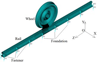
a) Whole model
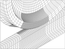
b) Details
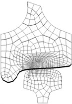
c) Contact region
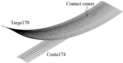
d) Contact elements
3.2. Boundary conditions
3.2.1. Displacement boundary conditions
When the train is moving, the wheel is in rolling, rolling-sliding or sliding state. The translational speed of wheel is different from the circumferential speed. In order to characterize the moving, the creep ratio is adopted [14]. It is:
where is translational speed of wheel axle, which is made up of both relative sliding speed () and rotating speed (). is angular velocity. is the radius of wheel.
In the process of calculation, the linear displacement and angular displacement are applied to the wheel. , , are the three axes of the whole coordinate system (see Fig. 1(a)), and respectively presents the transverse axis, vertical axis and longitudinal axis. The moving time is marked as . can be expressed as follow:
The initial rotation angle is equal to 0. Considering the Eq. (5), the Eq. (6) can be rewritten:
Moreover, the longitudinal and transverse displacements on the two rail end sections are constrained. The vertical displacements at the bottom of foundation springs are constrained. The vertical displacements at the top of the fastener are also constrained. The wheel can move in the longitudinal and vertical direction, but not move in the transverse direction.
3.2.2. Thermal boundary conditions
After the temperature rise of wheel/rail, the convection heat transfer and heat radiation are governed by:
where is convective heat coefficient. is temperature of wheel/rail. is surrounding temperature. is emission rate. is Stefan-Boltzmann constant.
3.3. Calculation parameters
The axle load of train is 20 t. In other words, the force subjected by each wheel is 100 kN. The stiffness, damping and initial pre-force of a single fastener are 2 MN/m, 1 kN·s/m and 10 kN respectively. The distance between the foundation springs along longitudinal direction is 0.6 m. The total stiffness of the foundation springs is 50 MN/m [15].
Table 1Mechanical parameters
(℃) | Young’s modulus (GPa) | Poisson’s ratio | Yield stress (MPa) | Tensile strength (MPa) |
25 | 209 | 0.30 | 608 | 1000 |
100 | 207 | 0.30 | 608 | 998.9 |
650 | 105 | 0.36 | 502 | 985.7 |
1000 | 50 | 0.39 | 237.9 | 740.9 |
1450 | 2.1 | 0.40 | 7 | 42 |
Table 2Thermal parameters
(℃) | Specific heat capacity (J/(kg·℃)) | Conductivity (W/(m·℃)) | Thermal expansion ×10-6 (/℃) | Friction coefficient |
25 | 490.1 | 47.7 | 11.0 | 0.334 |
100 | 499.9 | 48.9 | 11.6 | 0.301 |
650 | 571.5 | 57.8 | 14.8 | 0.139 |
1000 | 617.1 | 63.4 | 15.7 | 0.085 |
1450 | 671.8 | 76.4 | 16.1 | 0.045 |
The moving speed measured on a 8 section marshalling CRH3 EMU is 36 km/h [10]. The translational distance is 100 mm [12]. is the gravitational acceleration, and the value is 10 m/s2. The mechanical and thermal parameters are listed as Table 1 and Table 2 [12].
4. Results
In this paper, the wheel/rail frictional heat and dynamic characteristics under four cases are calculated by finite element model. The four situations are respectively rolling ( 0), sliding ( 1) and rolling-sliding ( 0.4, 0.7). At last, the influences of braking speeds on the contact force of wheel/rail are tested ( 1).
4.1. Temperatures of wheel/rail contact surface
Fig. 2(a) and (b) show the temperature fields of the contact surfaces when the creep ratio is equal to 0.4. Fig. 2(c) describes the relationship between maximum temperatures and creep ratios. When the creep ratio is not equal to zero, the friction heat will be generated at the wheel/rail contact interface due to the relative sliding speed between the wheel and rail surface. Fig. 2(a) and 2(b) indicate that the high temperature regions locate at the contact center, and decrease from center outward gradually. The maximum temperatures of wheel and rail surface are respectively 216.3 ℃ and 195.1 ℃ when creep ratio is equal to 0.4. Because the translational distance and the translational speed of wheel axle are constants, the creep ratio is proportional to the relative sliding speed (see Eq. (5)). According to the Eq. (2), the temperatures will ascend when the relative speeds increase (see Fig. 2(c)). The friction heat will cause the wheel/rail surface to peel, which can worsen the contact states of wheel/rail [17]. Therefore, the train should be braked under the condition of small creep ratios at the stations.
Fig. 2Temperatures (℃, t= 0.01 s)
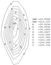
a) Wheel ( 0.4)
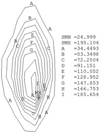
b) Rail ( 0.4)
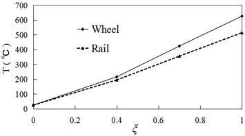
c) Temperature vs creep ratios
4.2. Accelerations of wheel/rail
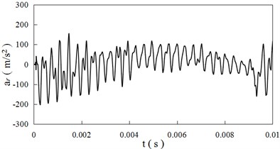
In order to study the dynamic behaviors of wheel/rail, two nodes are selected. The one is the center of wheel axle, and the other locates at the middle position of wheel/rail contact on the rail surface [16]. The acceleration time curves of the two nodes are shown as Fig. 3(a) and 3(b) when the creep ratio is equal to 0 respectively. The relationships between the vertical accelerations of nodes and creep ratio are presented as Fig. 4.
Fig. 3 shows the vertical accelerations of wheel/rail vibrate violently with the time. The acceleration variation curves of wheel and rail are different. The maximum absolute vertical acceleration of wheel is larger than the value of rail. The change rules of acceleration of wheel and rail are similar at different creep ratios. The maximum absolute vertical accelerations of wheel and rail are respectively 468 m/s2 and 232 m/s2 when the creep ratio is 0. The field measured value of rail is 261 m/s2 in Ref. [10, 18], the value is very close to calculation result in this paper.
Fig. 4 shows the maximum accelerations of wheel and rail descend with the creep ratio. It is because that the temperatures of wheel/rail contact region increase with creep ratios (see Fig. 2(c)). The temperature rise softens the material, and weakens the mechanical interactions between wheel and rail. Therefore, the vertical accelerations of wheel/rail decrease with the creep ratios.
Fig. 3Acceleration time curves (ξ= 0)
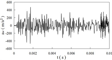
a) Wheel
b) Rail
Fig. 4Accelerations vs creep ratio
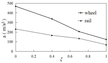
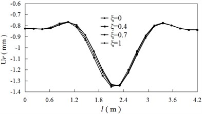
Fig. 5Vertical displacement vs rail length
4.3. Displacements
Fig. 5 presents the relationships between the vertical displacement of rail top surface and rail length when the time is equal to 0.005 s. The minimum displacement of wheel and rail is respectively –1.16 mm and –1.33 mm. (The negative sign means the vertical displacement is downward.) Because the external force and spring stiffness are not changed, the differences between vertical displacements at different creep ratios are very small. The contact position of wheel/rail locates at the middle of rail, so the vertical displacement is large near the contact area. Similarly, the influence of creep ratio on the vertical displacement is not obvious (see Fig. 5).
4.4. Influence of braking speed
4.4.1. Experimental method
In this section, a new experimental device used for testing the wheel/rail contact characteristics is designed, and it is shown as Fig. 6. The radius of wheel is 64 mm. The radius of wheel in the contact region along transverse direction is 30 mm. The top surface of rail in transverse is machined into a curved surface, and its radius is 300 mm. The sizes of wheel/rail is illustrated as Fig. 6(c). The experimental load is 2 kN. Because the axial force of connecting rod 10 is proportional to the contact force of wheel/rail in vertical direction (see Fig. 6(b)), the axial strain of connecting rod 10 is measured for calculating the contact force. The material components of wheel/rail are listed as Table 3.
Table 3Material components of wheel/rail
(%) | (%) | (%) | (%) | (%) | |
Wheel | 0.40-0.70 | 0.80-1.00 | 0.30-0.50 | ≤0.045 | ≤0.04 |
Rail | 0.62-0.77 | 1.35-1.65 | 0.15-0.37 | ≤0.05 | ≤0.04 |
Fig. 6Figures of experimental device
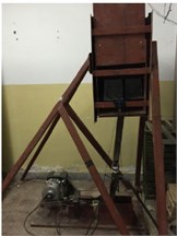
a) Experimental device
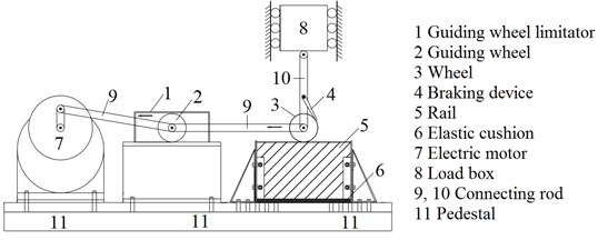
b) Components of experimental device
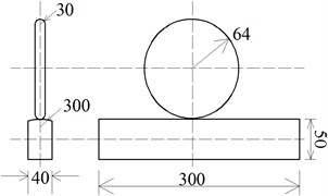
c) Geometrical dimensions of wheel/rail test specimens (mm)
4.4.2. Experimental results
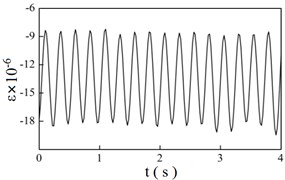
Fig. 7 shows the strain time history curves at different braking speeds ( 1). At the same time, the dynamic factors are calculated by both experiments and finite element model. The dynamic factor is defined as:
where is dynamic contact force of wheel/rail, and is the static contact force. The dynamics factors and errors are listed in Table 4.
Table 4Experimental and numerical results
Braking speeds (m/s) | 1.5 | 2 | 2.5 | 3 | |
Average strain of troughs (×10-5) | –1.352 | –1.371 | –1.762 | –1.981 | |
Dynamic factors | Experimental results | 1.054 | 1.121 | 1.206 | 1.306 |
Numerical results | 1.031 | 1.116 | 1.245 | 1.295 | |
Errors (%) | 2.182 | 0.446 | 3.234 | 0.842 | |
Fig. 7 shows the vibration frequencies of wheel ascend gradually with the braking speeds. And the average strain of troughs in the strain time history curves decreases with the growth of braking speeds, which indicates that the normal contact force of wheel/rail becomes larger. Table 4 indicates that the dynamics factors increase with the braking speeds. On the other hand, the dynamics factors calculated through the experimental method and finite element method are very close, the maximum error is 3.234 %.
Fig. 7Strain time history curves at different braking speeds
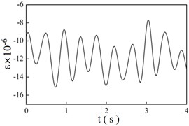
a) 1.5 m/s
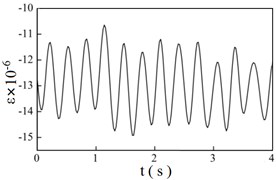
b) 2 m/s
c) 2.5 m/s
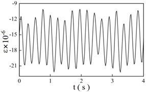
d) 3 m/s
5. Conclusions
Based on the thermal-mechanical coupling model of 3-D wheel/rail-foundation contact system and the new experimental device, the temperatures and dynamic characteristics of wheel/rail are analyzed. From the above analyses, some conclusions can be drawn as following:
1) On the contact surfaces, the high temperature regions locate at the contact center. The temperatures ascend gradually with the growth of creep ratios. The maximum temperature of wheel and rail surface is respectively 626.1 ℃ and 514.2 ℃ when the creep ratio is equal to 1.
2) The creep ratios have a significant influence on the vertical acceleration of wheel/rail, and the acceleration decreases gradually with the increase of the creep ratios. The maximum vertical acceleration of wheel and rail is respectively 468 m/s2 and 232 m/s2 when the creep ratio is equal to 0.
3) Because the external force and spring stiffness do not change, the differences between vertical displacements are very small at different creep ratios. The maximum absolute vertical displacement of wheel and rail is respectively 1.16 mm and 1.33 mm.
4) The braking speed have an obvious effect on the wheel/rail interaction. The normal contact force of wheel/rail and the dynamic factor ascend gradually with the growth of braking speeds. The dynamics factors calculated by two methods are very close, and the maximum error is 3.234 %.
5) The 3-D wheel/rail contact model and experimental method can precisely reflect the contact characteristics of wheel/rail. The analysis data have significance to design the high-speed railway station and components of wheel/rail.
References
-
Dudkin E. P., Andreeva L. A., Sultanov N. N. Methods of noise and vibration protection on urban rail transport. Procedia Engineering, Vol. 189, 2017, p. 829-835.
-
Han Jian, Xiao Xinbiao, Wu Yue, Wen Zefeng, Zhao Guotang Effect of rail corrugation on metro interior noise and its control. Applied Acoustics, Vol. 130, 2018, p. 63-70.
-
Meehan Paul A., Liu Xiaogang Modelling and mitigation of wheel squeal noise amplitude. Journal of Sound and Vibration, Vol. 413, 2018, p. 144-158.
-
Gao Guangyun, Song Jian, Chen Gongqi, Yang Jun Numerical prediction of ground vibrations induced by high-speed trains including wheel-rail-soil coupled effects. Soil Dynamics and Earthquake Engineering, Vol. 77, 2015, p. 274-278.
-
Cui Xiaolu, Chen Guangxiong, Zhao Jiangwei, Yan Wenyi, Ouyang Huajiang, Zhu Minhao Field investigation and numerical study of the rail corrugation caused by frictional self-excited vibration. Wear, Vol. 376, Issue 377, 2017, p. 1919-1929.
-
Lundberg Oskar E., Finnveden Svante, Björklund Stefan, Pärssinen Mikael, Arteaga Ines Lopez A nonlinear state-dependent model for vibrations excited by roughness in rolling contacts. Journal of Sound and Vibration, Vol. 345, 2015, p. 197-213.
-
Zou Chao, Wang Yimin, Wang Peng, Guo Jixing Measurement of ground and nearby building vibration and noise induced by trains in a metro depot. Science of the Total Environment, Vol. 536, 2015, p. 761-773.
-
Yang Zhen, Boogaard Anthonie, Chen Rong, Dollevoet Rolf, Li Zili Numerical and experimental study of wheel-rail impact vibration and noise generated at an insulated rail joint. International Journal of Impact Engineering, Vol. 113, 2018, p. 29-39.
-
Fang Lianmin, Zhu Zhihui, Wang Liding, Yu Zhiwu, Cai Chengbiao Analysis of train induced random vibration of high-speed railway station with “integral station-bridge structure”. Journal of the China Railway Society, Vol. 39, Issue 9, 2017, p. 117-125, (in Chinese).
-
Xie Weiping, Xu Wei Vehicle-induced vibration responses of a rail box girder in Wuhan station. Journal of Vibration and Shock, Vol. 31, Issue 8, 2012, p. 186-190, (in Chinese).
-
Alawadhi Esam M. Finite Element Simulations Using Ansys. 2nd Edition, CRC Press, Boca Raton, USA, 2015.
-
Wu Yaping, Wei Yunpeng, Liu Yang, Duan Zhidong, Wang Liangbi 3-D analysis of thermal-mechanical behavior of wheel/rail sliding contact considering temperature characteristics of materials. Applied Thermal Engineering, Vol. 115, 2017, p. 455-462.
-
Liu Yang, Liu Zhen, Wu Yaping, Wei Yunpeng, Duan Zhidong Thermo-elastoplastic analysis of wheel-rail sliding contact stress with variable friction coefficient. China Railway Science, Vol. 5, 2015, p. 3-4, (in Chinese).
-
Popov Valentin L. Contact Mechanics and Friction, Physical Principles and Applications. Springer, 2010.
-
Wang Kaiyun, Cai Chengbiao, Zhu Shengyang Vertical dynamic model and vibration characteristic of rail fastening system. Engineering Mechanics, Vol. 30, Issue 4, 2013, p. 146-149, (in Chinese).
-
Wanming Zhai Vehicle-Track Coupled Dynamics. 4th Edition, CSPM, Beijing, China, 2015 (in Chinese).
-
Ahlstom J., Karlsson B. Modeling of heat conduction and phase transformations during wheel sliding-theoretical predictions and comparison with results of full-scale experiments. Wear, Vol. 253, Issue 1, 2002, p. 291-300.
-
Zhu Zhihui, Guan Bin, Yu Zhiwu, Guo Xiangrong Coupling vibration response of train-station-bridge integration for large-scale passenger station. China Railway Science, Vol. 35, Issue 5, 2014, p. 38-46, (in Chinese).
About this article

This study is supported by the National Natural Science Foundation of China, China (Grant No. 51236003).
