Abstract
In this paper, two sets of comparative fatigue tests on weathering steel-concrete composite girders were carried out in the context of steel-concrete composite girder bridges. The load-deflection relationship of the weathering steel-concrete composite girders under fatigue loading in different environments was investigated contrastively. The experimental results show that under the coupled effect of corrosive environment and fatigue load, the weathering steel still shows obvious corrosion; the simple fatigue load has no significant effect on the stiffness and fatigue modulus of the weathering steel-concrete composite beam, while the coupled effect of corrosive environment and fatigue has a significant weakening effect on the stiffness of the beam, and the weakening of concrete is apparently greater than that of steel beam.
Highlights
- Two sets of comparative fatigue tests on weathering steel-concrete composite girders were carried out in the context of steel-concrete composite girder bridges.
- The load-deflection relationship of the weathering steel-concrete composite girders under fatigue loading in different environments was investigated contrastively.
- Under the coupled effect of corrosive environment and fatigue load, the weathering steel still shows obvious corrosion.
1. Introduction
Steel-composite girders have the advantages of high load capacity, high stiffness, great stability and good seismic performance, and thus were widely used in the field of bridge structures and building structures, but the corrosion resistance and fire resistance of steel parts are poor [1]. In recent years, weathering steel has been used in the lower part of steel-composite girders in some projects to enhance their durability.
However, during the use of the bridge, it is also subjected to the action of dynamic loads generated by vehicles, and under the action of cyclic stresses, fatigue damage accumulates, and when the accumulation reaches a certain level the member will undergo sudden damage. Fatigue damage requires low stress thresholds, no obvious signs of damage, and often has catastrophic consequences when it occurs [2]-[4]. Up to now there are relatively few studies on the performance of steel-concrete combination beams under the coupling effect of corrosion and fatigue. The main research work has been the study of fatigue performance of combined beams after corrosion, focusing on the change law of peg corrosion and steel beam corrosion on the fatigue performance of combined beams [5].
In order to understand the fatigue performance of weathering steel-composite composite beams under corrosion and better use in bridge construction, corrosion fatigue test is an effective way to study [6]-[7]. In this paper, based on the existing research, the comparative fatigue test of weathering steel-composite composite beams is carried out in combination with the stress state of the real bridge, and the influence of the coupling effect of corrosive environment and fatigue load on the degradation of mechanical properties of weathering steel-composite composite beams is obtained, which provides test reference for the actual engineering construction.
2. Fatigue test
2.1. The tested weathering steel-composite composite beams
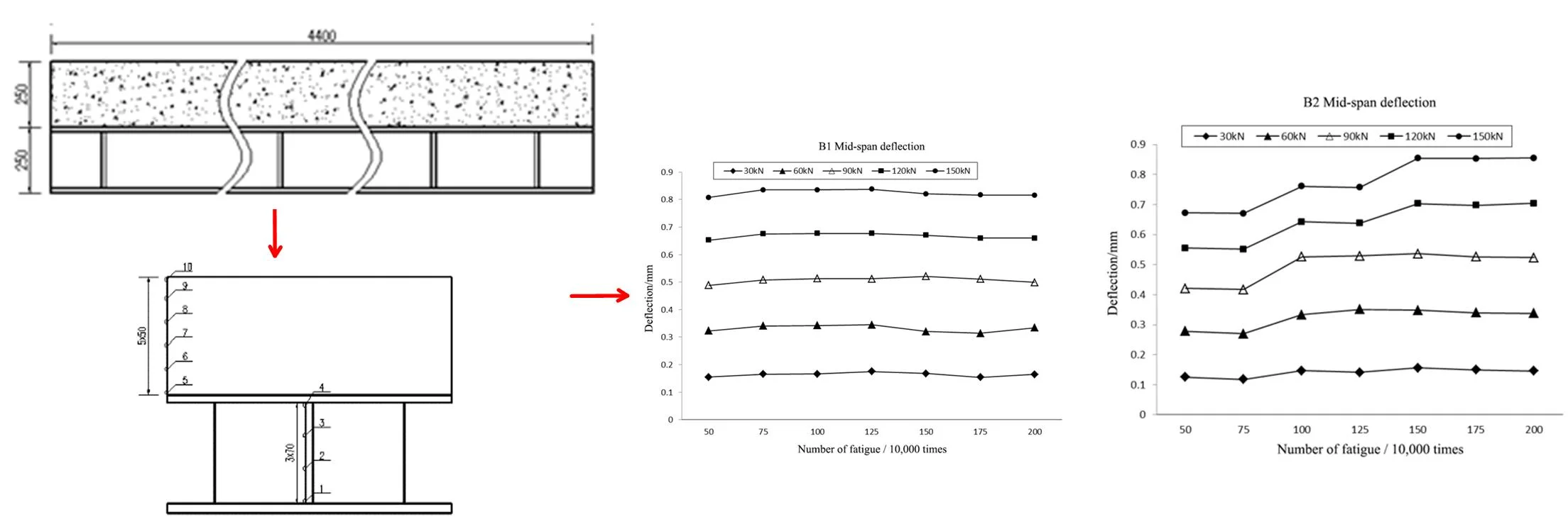
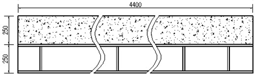
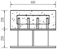
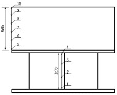
In this test, two weathering steel-composite composite beams with the same structure and material, numbered L1 and L2, were designed and fabricated as comparison beams to carry out the fatigue tests without and with corrosion respectively. The design strength grade of concrete is C50, and the material of steel beam is no-coating weathering steel (Q420qNHD); the pins are ML15 welded pins with 22 mm diameter and 150 mm length; the grade of reinforcement is HRB400, and the diameter of longitudinal reinforcement and hoop is 20 mm, as shown in Fig. 1.
Fig. 1Geometry of specimen (unit: mm)
The 1/2 cross section is the displacement measurement point, the displacement sensor is arranged at the bottom of the 1/2 cross section, the 1/4 cross section is the strain measurement point, and the actual patch position is deviated by 50 mm due to the steel beam cross partition at this location, the vertical spacing of the strain gauges on the steel beam web is 70 mm, and the vertical spacing of the strain gauges on the side of the concrete beam is 50 mm, as shown in Fig. 2.
Fig. 2Measurement points arrangement
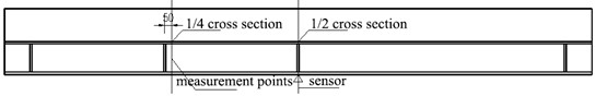
a)
b) 1/4 cross-section strain gauge
2.2. Testing device and loading method
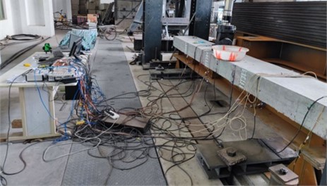
After the age of the concrete exceeded 28 days, all tests were completed in the structural testing laboratory of Sichuan Construction Vocational College. The loading system used the MTS multi-channel electro-hydraulic servo coordination system (Fig. 3), and in order to simulate the actual stress state, the trans-medium amplitude repetitive fatigue loading method was used, and the load waveform was a sine wave, and the computer controlled the magnitude and application time of the load.
To conduct the fatigue tests under corrosive environment in the laboratory, a corrosive environment simulation chamber sealing system was developed. The test system consists of a box made of 5 mm thick transparent PVC sheets, in which the test beam is sealed. There is an opening on the top plate of the box as an actuator channel. To maintain the seal, a flexible sealing sleeve was provided at the opening position, and an elastic rubber ring is used for fixing. Based on the monitoring data of the actual bridge environment, a corrosion solution with a pH value of 4.03 was prepared with 5 % NaCl+H2SO4. To simulate a corrosive environment, a high-pressure atomizing sprayer was installed inside the sealed box to spray the corrosive solution on the test beam every 30 minutes for a duration of 10 minutes.
Before the formal fatigue test, pre-pressure to eliminate the internal components without sufficient action. The pre-pressure was loaded by graded loading, 0 kN - 50 kN - 100 kN - 150 kN - 50 kN - 0 kN, with each level of load held for 3 min, while measuring the data of each measurement point, recording the displacement and strain, and verifying the validity of the finite element model. The lower and upper fatigue loads are 10 kN and 160 kN, and the loading frequency is 2.5 Hz. The fatigue cyclic loading is stopped every 250,000 times to check the appearance and do static load test, starting from the lower load limit, loading in 5 steps of 30 kN each, loading to the upper load limit, and then unloading step by step. In the process of loading and unloading, the load is held for 3min at each level, and the data of each measurement point is measured and the displacement and strain are recorded at the same time.
Fig. 3Fatigue loading system (image copyright belongs to Liangliang Zhang)
3. Experimental results and analysis
The two combined beams B1 and B2 in this test had identical test conditions and working conditions, except for the different test environments (B1 for natural environment and B2 for corrosive environment). At the beginning of pre-pressing, both beams made a slight sound of friction between the reinforcement (or anchor nails) and concrete, and after pre-pressing, a residual deformation of about 0.5 mm was produced.
3.1. Appearance
During the fatigue test, no obvious damage was found during each stoppage to check the appearance of the test beam. When the fatigue number of the combined beam reached 2 million times, the steel-mixed intersection still did not separate. There are mainly two reasons, the upper fatigue load limit value of the combination beam is small, which does not cause large relative slip of the combination beam, and the configuration of the shear connectors meets the design requirements of the shear connectors in the specification. Therefore, the fatigue damage of the pegs was small after the combined beam was subjected to fatigue loading. The concrete surface and the triple junction of the steel beam lower flange plate, steel beam web and stiffening ribs of the steel beam, i.e., the stress concentration area of the steel beam, i.e., the fatigue-prone area, also showed no damage such as cracks. there was no significant change in the appearance of the B1 steel beam before and after the test, while the B2 steel beam showed significant rusting.
3.2. Deflection
Fig. 4 gives the mid-span deflections of B1 and B2 after experiencing different number of cycles. From Fig. 4, it can be seen that the mid-span deflection curves of beam B1 under different fatigue loads are basically horizontal straight lines; the mid-span deflection curves of beam B2 under different fatigue loads are basically rising straight lines.
Fig. 4The mid-span deflection of beams under different fatigue loads
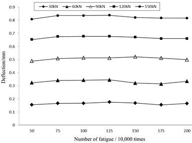
a) B1
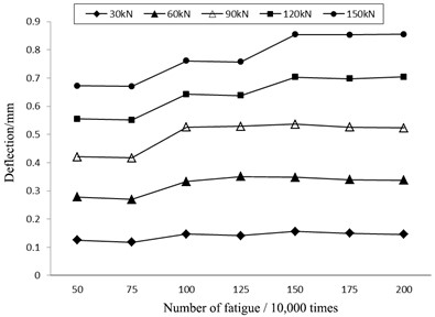
b) B2
Table 1Table of deflection increments (1 million times)
Parameters | Test beam | 30 kN | 60 kN | 90 kN | 120 kN | 150 kN |
Deflection increment (mm) | B1 | 0.010199 | 0.011731 | 0.017386 | 0.02435 | 0.030025 |
B2 | 0.015648 | 0.04676 | 0.079293 | 0.083642 | 0.095644 | |
Increase in deflection | B1 | 6.6 % | 3.6 % | 3.6 % | 3.7 % | 3.7 % |
B2 | 10.1 % | 16.8 % | 18.8 % | 15.1 % | 14.2 % |
Table 2Table of deflection increments (2 million cycles)
Parameters | Test beam | 30 kN | 60 kN | 90 kN | 120 kN | 150 kN |
Deflection increment (mm) | B1 | 0.010059 | 0.011206 | 0.01033 | 0.00768 | 0.017476 |
B2 | 0.020205 | 0.059053 | 0.102237 | 0.14969 | 0.183188 | |
Increase in deflection | B1 | 6.5 % | 3.5 % | 2.1 % | 1.2 % | 2.2 % |
B2 | 13.0 % | 21.2 % | 24.3 % | 27.0 % | 27.3 % |
In order to further compare the stiffness degradation rates of the 2 beams under different environments, the deflection increment is defined in this paper as the difference in deflection between the static loading of each test beam before the fatigue test and the static loading after experiencing the fatigue load, as shown in Table 1 and Table 2. As shown in Tables 1 and 2, after experiencing fatigue loading, B1 and B2 both produce certain deflection increments, and B2 deflection increments are larger than B1; comparing B1 and B2 deflection increments at 150 kN after experiencing 1 million and 2 million fatigue loads, B1 slightly changes, with deflection increments of 3.7 % and 2.2 %, respectively, and B2 significantly changes, with deflection increments of 14.2 % and 27.3 %, the deflection increase under the rest of the load also shows the same pattern.
It can be seen that the fatigue loading alone does not lead to significant degradation of the beam stiffness; while the coupling effect of corrosive environment and fatigue has a significant weakening effect on the beam stiffness.
4. Conclusions
1) Regardless of the environment and fatigue damage, the strain distribution along the section height of the weathering steel-composite composite beam is consistent with the flat section assumption.
2) Under pure fatigue loading, the weathering steel still has good corrosion resistance, but under the coupling effect of corrosive environment and fatigue, the weathering steel will still show significant rusting.
3) The simple fatigue load has no significant effect on the stiffness of the weathering steel-composite combination beam, while the coupling effect of corrosive environment and fatigue has a significant weakening effect on the stiffness of the beam.
References
-
J. Nie and Z. Yu, “Research and application of steel-concrete composite beams in China,” (in Chinese), China Civil Engineering Journal, Vol. 32, No. 2, pp. 3–8, 1999.
-
C. N. Dolling and R. M. Hudson, “Weathering steel bridges,” Proceedings of the Institution of Civil Engineers – Bridge Engineering, Vol. 156, No. 1, pp. 39–44, Mar. 2003, https://doi.org/10.1680/bren.2003.156.1.39
-
J. Zhu et al., “Research on corrosion behavior, mechanical property, and application of weathering steel in bridges,” China Journal of Highway and Transport, Vol. 32, No. 5, pp. 1–16, 2020, https://doi.org/10.11918/201907021
-
K. Zheng et al., “Development of domestic and international corrosion fatigue test technologies for weathering steel,” Journal of Harbin Institute of Technology, Vol. 53, No. 3, pp. 1–10, 2021, https://doi.org/10.11918/201907021
-
Z. Haipeng, C. Ju, J. Weiliang, and M. Jianghong, “Fatigue behavior of steel-concrete composite beams with corroded studs,” Journal of Building Structures, Vol. 40, No. 5, pp. 89–95, 2019.
-
L. Deng, W. Yan, and L. Nie, “A simple corrosion fatigue design method for bridges considering the coupled corrosion-overloading effect,” Engineering Structures, Vol. 178, pp. 309–317, Jan. 2019, https://doi.org/10.1016/j.engstruct.2018.10.028
-
W. Zhang and H. Yuan, “Corrosion fatigue effects on life estimation of deteriorated bridges under vehicle impacts,” Engineering Structures, Vol. 71, pp. 128–136, 2014, https://doi.org/10.1016/j.engstruct. 2014.04.004
About this article

This research was supported by the Science and Technology Research Program of Chongqing Expressway Engineering Consultant Co., Ltd. (Grant No. H20211108).
The datasets generated during and/or analyzed during the current study are available from the corresponding author on reasonable request.
The authors declare that they have no conflict of interest.
