Abstract
In order to enhance the ride comfort, stability, and safety of heavy trucks. Based on the dynamic characteristics of the parameters of heavy trucks and its dynamic model, a multi-objective genetic algorithm are developed in the MATLAB environment and applied to optimize the dynamic parameters of vehicles. The weighted root-mean-square (RMS) accelerations of the cab and driver seat vibrations are chosen as the study goals to evaluate the results under different vehicle conditions. The obtained results show that the optimal parameters of vehicles are significantly enhanced the vehicle ride comfort under different operation conditions. Particularly, the weighted RMS accelerations of the and are significantly reduced by 26.3 % and 35.3 % under the ISO level B of the road surface, and a vehicle speed region from 17.5 m/s to 20 m/s (63 km/h to 72 km/h).
Highlights
- The optimization of heavy truck dynamic parameters on the vehicle's ride comfort under the random road excitation.
- A dynamic model of the vehicle with 10 degrees of freedom is established to simulate and analyze the results.
- The genetic algorithm is applied to optimize the heavy truck parameters.
- The weighted RMS accelerations of the a_wz and a_wpc are significantly reduced by 26.3 % and 35.3 % under the ISO level B of the road surface, and a vehicle speed region from 17.5 m/s to 20 m/s (63 km/h to 72 km/h).
1. Introduction
The heavy vehicles are not only required to enhance the ride comfort but also required the improvement of the road friendliness. In order to solve this problem, the heavy truck suspension system ought to be able to isolate the sprung mass from road-induced disturbances as well as reducing the dynamic-load-coefficient of tire force from the axle of the heavy trucks within the limit of set working space under different operator conditions [1-4].
The ride comfort of vehicles has been greatly affected by the design parameters of the vehicles, especially parameters of the vehicle suspension systems. Therefore, researchers have continuously developed advanced suspension systems such as air suspension systems [5, 6], semi-active suspension systems [7-9], or the control suspensions of the cab [10, 11]. The research results have also significantly improved the vehicle’s ride comfort while traveling. However, previous studies have often focused on optimizing or controlling an individual suspension system, an overall rating of the car that is less considered. Besides, the published studies is shown that the semi-active suspension systems can improve the vehicle’s ride better than its optimized suspension parameters [1, 12, 13]. However, the installation of the controlled suspension can lead to an increase in the price. In addition, for heavy trucks, the vehicle is often used by with three suspension systems with the different damping and stiffness parameters for the vehicle, cab, and driver’s seat. Therefore, all the vehicle suspension systems equipped with the control suspensions are impossible. Previous studies were only concerned with controlling the vehicle suspension system [5, 7, 12] or the suspension system of the cab and seat [11, 14] to improve the ride comfort. There are no studies to suggest suspension control for the whole system. For heavy trucks are supported by various suspensions of the vehicle, cab, and seat; it can be more efficient if the optimization of their dynamic parameters and control of a vehicle or cab suspension system. However, multi-objective optimization of the parameters of heavy truck suspension systems is a complex problem, and it has not yet fully paid attention [12, 13].
Based on a vehicle dynamic model and an optimal region of the vehicle dynamic parameters proposed in Part-1, a multi-objective genetic algorithm is developed and applied to optimize the vehicle dynamic parameters. The weighted RMS accelerations of the vertical driver’s seat and cab pitch angle have been used to evaluate the vehicle ride comfort under the different simulation conditions of the road surfaces and speeds. The aim of this study is the optimization of the vehicle dynamic parameters to improve vehicle ride comfort.
2. Mathematical model
2.1. The dynamic model of heavy trucks
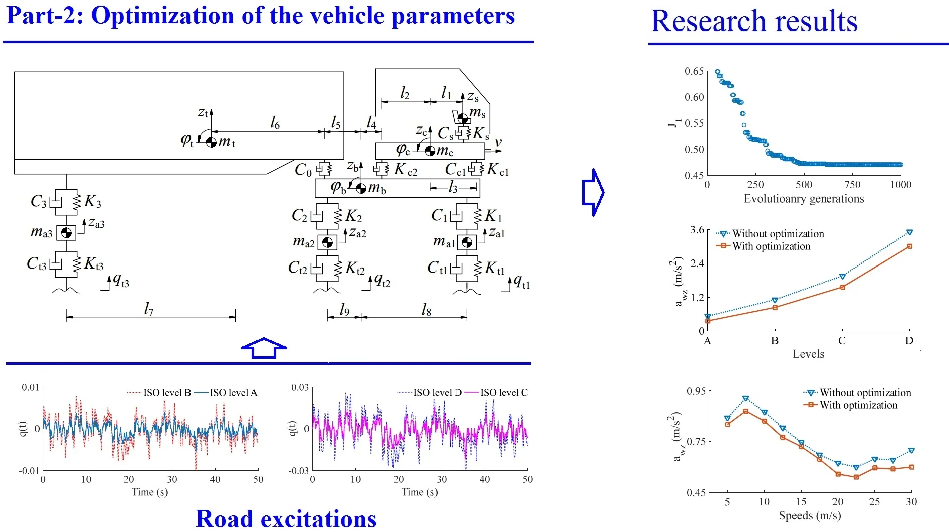
Based on research results in Part-1, the dynamic parameters of the vehicle suspension system with the vehicle dynamic model are plotted in Fig. 1, where, , , , , and are the displacements in the -direction of the seat, cab, body, trailer, and axle; , , and are the pitch angles of the cab, body, and trailer, respectively; , , , and are the damping parameters of the suspension systems of the seat, cab, vehicle, and wheel, respectively; , , , and are the stiffness parameters of the suspension systems of the seat, cab, vehicle, and wheel, respectively; , , , , and are the mass of the seat, cab, body, trailer, and vehicle’s unsprung; are all geometric dimensions ( 1,…,3, 1, 2, 1,…, 9).
Fig. 1Lumped parameter model of heavy trucks
Based on the lumped parameter model of the vehicle in Fig. 1 and Newton-II law, the motion equations of the vehicle is represented by the matrix form as in Eq. (1):
where , , , and are the matrices of the mass, passive damping, active damping, and stiffness of the vehicle, is the displacement vector, and is the excitation force vector of the vibrations from the road surface.
2.2. Road surface roughness
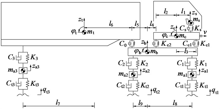
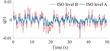
Based on the established method of the random road surface in Section 3 of Part-1, and according to the standard ISO 8068 [15], four types of level A to D of the road surface roughness are established and simulated at 72 km/h, as shown in Fig. 2. The excitation of these road surfaces is then applied for the simulation process of the vehicle.
Fig. 2Road profiles according to ISO 8068
2.3. Evaluation criteria of ride comfort
According to the ISO 2631-1 [16], the influence of the vibration on the driver’s health and ride comfort had been mainly assessed through the weighted RMS (Root-Mean-Square) of the acceleration responses, and it is described as follows:
where and are the acceleration responses of the driver’s seat and cab that depend on the time of measurement .
The weighted RMS acceleration responses of the vertical driver’s seat and the pitch angle of the cab of heavy trucks can be calculated from Eq. (2), their values are then compared with , as given in Table 1.
3. Optimization of the vehicle dynamic parameters
3.1. Multi-objective genetic algorithm (MGA)
The MGA is a multi-optimization method via the natural selection, and it is defined as finding the Maximum or Minimum functions of one or more goals. Thus, the MGA is simply described by the mathematical method as follows [5, 17-18]:
Find the vector for the optimization of the function :
Subject to 0, 1, 2,…, , 0, 1, 2,..., , where is the vector of the study goals, and must be obtained the Maximum or Minimum values. and are the boundary conditions of the optimal regions.
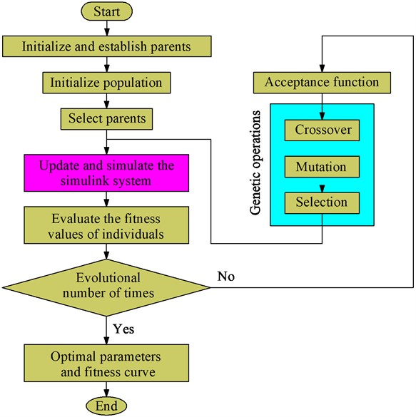
The MGA structure has been defined by the steps of “encoding, population initialization, fitness evaluation, parent selection, genetic operations (crossover and mutate), and termination criterion”. Therefore, a flowchart of the MGA program for the optimization of the vehicle dynamic parameters is plotted in Fig. 3.
3.2. Application of the GA for optimization of the vehicle dynamic parameters
The goal of this study to apply the MGA is to optimize the parameters and of the damping and stiffness of the suspension systems of the seat, cab, vehicle, and wheel to reach the Minimum values of the weighted RMS values of the driver’s seat vibration () and cab’s pitch vibration () via the lumped parameter model of the vehicle and the AGA model in Figs. 1 and 3. Therefore, the MGA’s structure has been established as follows:
(1) Encoding and initial populations: The dynamic parameters of and are connected to the chromosome regarded as the vectors to reduce the length of the chromosome and enhance the seeking speed of the AGA. Besides, the initial population, the generated individuals is random. With each gene, it is also randomly chosen in its region. In this study, the initial population size is established by 200.
Fig. 3The flowchart of the MGA
(2) Research values and fitness functions: In this study, the Minimum RMS values of the acceleration vibrations of the driver’s seat () and cab () given in Eq. (2) have been chosen as the study aims. To research the Minimum RMS values of the acceleration vibrations, two fitness values of and are simplified to compute the study aims as follows [5]:
The individuals with the smaller fitness values and which are obtained via the subsystem model indicate that the obtained dynamic parameters are the better. Thus, the individuals have been updated before the evolution process ends, and the optimal result of the individuals is obtained.
(3) The process of genetic operations: Herein, the genetic operations have two process including crossover and mutation operations. This study chooses the crossover probability of 0.95 and mutation probability of 0.05 in 1000 generations for the process of genetic operations. In the mutation operation of each individual with a probability of 0.05, the new individual is then generated and added in the population. Finally, based on two fitness values of and , only the better individuals have been selected to perform next generations. For the termination criterion, it is happen when the change of the or between two adjacent generations below 10-3, and the results of the congregation are then obtained. The MGA code is given in Table 1.
Table 1The code of the MGA program
procedure MGA |
begin 0; initialize ; evaluate ; while not finished do begin ; select from ; reproduce pairs in begin crossover from ; mutation from ; selection from ; end evaluate end end |
Table 2Lumped parameters of heavy truck
Parameter | Value | Parameter | Value | Parameter | Value |
/ kg | 0.45×10³ | / N.m-1 | 5.454×10⁵ | / N.m.s-1 | 0.75×10³ |
/ kg | 1.025×10³ | / N.m-1 | 5.454×10⁵ | / N.m.s-1 | 0.75×10³ |
/ kg | 1.025×10³ | / N.m-1 | 1×10⁵ | / N.m.s-1 | 0.2×10³ |
/ kg | 12.5×10³ | / N.m-1 | 1×10⁵ | / m | 0.2 |
/ kg | 3.6×10³ | / N.m-1 | 2×10⁴ | / m | 0.8 |
/ kg | 0.5×10³ | / N.m.s-1 | 1.5×10³ | / m | 1.3 |
/ kg | 0.12×10³ | / N.m.s-1 | 3×10³ | / m | 0.3 |
/ N.m-1 | 6.9×10⁵ | / N.m.s-1 | 3×10³ | / m | 4.1 |
/ N.m-1 | 1.38×10⁶ | / N.m.s-1 | 7.029×10³ | / m | 6.9 |
/ N.m-1 | 1.38×10⁶ | / N.m.s-1 | 2.409×10⁴ | / m | 4.0 |
/ N.m-1 | 1.02105 | / N.m.s-1 | 2.409×10⁴ | / m | 1.2; 4.8 |
4. Optimal results and discussions
4.1. Optimal results
To find the optimal parameters for the heavy trucks, assuming that the vehicle travels under a random road surface of ISO level B at 72 km/h forward speed. The vehicle’s parameters as listed in Table 2 and its road surface excitation as plotted in Fig. 2 are chosen as the parameter inputs of the optimal model in Fig. 3. Additionally, based on the research results in Part-1, an optimal range of the vehicle dynamic parameters proposed to improve the vehicle ride comfort in Table 3 are used to limit the boundary conditions of the MGA. Therefore, the boundary conditions of the dynamic parameters for the MGA model are listed in Table 4. The MGA is then performed to find the optimal values of and in 1000 generations.
Table 3The optimal region of the vehicle dynamic parameters
Stiffness parameters | Damping parameters |
{0.6 to 1.0}× | {1.2 to 1.6}× |
{0.8 to 1.2}× | {1.2 to 1.6}× |
{0.6 to 1.0}× | {1.4 to 1.8}× |
{1.6 to 2.0}× |
Table 4The boundary conditions of the vehicle dynamic parameters for the MGA
Stiffness parameters | Damping parameters |
3.272×10⁵ ≤ ≤ 5.454×10⁵ | 2.89×10⁴ ≤ ≤ 3.85×10⁴ |
0.612×10⁵ ≤ ≤ 1.02×10⁵ | 2.89×10⁴ ≤ ≤ 3.85×10⁴ |
1.101×10⁶ ≤ ≤ 1.656×10⁶ | 8.43×10³ ≤ ≤ 11.25×10³ |
5.52×10⁵ ≤ ≤ 8.28×10⁵ | 0.9×10³ ≤ ≤ 1.2×10³ |
0.6×10⁵ ≤ ≤ 1.0×10⁵ | 0.9×10³ ≤ ≤ 1.2×10³ |
3.2×10⁴ ≤ ≤ 4.0×10⁴ | 0.28×10³ ≤ ≤ 0.36×10³ |
Fig. 4The curve of fitness values of the AGA
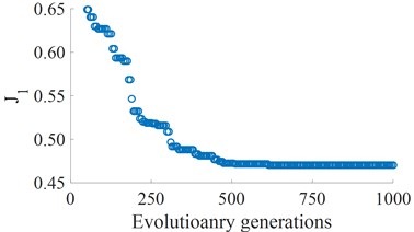
a) The fitness of the driver’s seat vibration
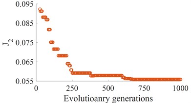
b) The fitness of the cab pitch vibration
Table 5The optimal results of stiffness parameters
×104 | ×105 | ×105 | ×105 | ×105 | ×105 | ×105 | ×106 | ×106 | |
0 | 2.000 | 1.000 | 1.000 | 1.020 | 5.454 | 5.454 | 6.900 | 1.380 | 1.380 |
1 | 3.112 | 0.911 | 0.922 | 0.889 | 0.443 | 0.463 | 7.876 | 1.554 | 1.665 |
2 | 3.920 | 0.674 | 0.703 | 0.733 | 0.397 | 0.445 | 7.232 | 1.453 | 1.650 |
3 | 3.612 | 0.766 | 0.754 | 0.765 | 0.532 | 0.543 | 6.804 | 1.389 | 1.445 |
4 | 3.801 | 0.798 | 0.801 | 0.803 | 0.458 | 0.467 | 6.543 | 1.136 | 1.233 |
... | ... | ... | ... | ... | ... | ... | ... | ... | ... |
660 | 3.852 | 0.803 | 0.802 | 0.797 | 0.446 | 0.455 | 6.454 | 1.125 | 1.202 |
662 | 3.841 | 0.810 | 0.813 | 0.754 | 0.424 | 0.434 | 6.354 | 1.122 | 1.119 |
700 | 3.832 | 0.811 | 0.814 | 0.748 | 0.415 | 0.420 | 6.315 | 1.120 | 1.118 |
701 | 3.832 | 0.811 | 0.814 | 0.744 | 0.415 | 0.418 | 6.313 | 1.120 | 1.118 |
702 | 3.832 | 0.811 | 0.814 | 0.744 | 0.415 | 0.418 | 6.313 | 1.120 | 1.118 |
... | ... | ... | ... | ... | ... | ... | ... | ... | ... |
1000 | 3.832 | 0.811 | 0.814 | 0.744 | 0.415 | 0.418 | 6.313 | 1.120 | 1.118 |
Table 6The optimal results of the damping parameters
×103 | ×103 | ×103 | ×103 | ×104 | ×104 | |
0 | 0.200 | 0.750 | 0.750 | 7.029 | 2.409 | 2.409 |
1 | 0.322 | 0.927 | 0.855 | 10.011 | 2.842 | 2.935 |
2 | 0.282 | 1.028 | 1.124 | 11.211 | 3.054 | 3.265 |
3 | 0.351 | 1.151 | 1.054 | 9.895 | 3.112 | 3.273 |
4 | 0.344 | 1.186 | 1.164 | 10.221 | 3.101 | 3.265 |
... | ... | ... | ... | ... | ... | ... |
660 | 0.336 | 1.165 | 1.186 | 10.544 | 3.227 | 3.245 |
662 | 0.332 | 1.162 | 1.183 | 10.522 | 3.352 | 3.364 |
700 | 0.331 | 1.161 | 1.176 | 10.464 | 3.346 | 3.355 |
701 | 0.331 | 1.161 | 1.173 | 10.465 | 3.342 | 3.351 |
702 | 0.331 | 1.161 | 1.173 | 10.465 | 3.342 | 3.351 |
... | ... | ... | ... | ... | ... | ... |
1000 | 0.331 | 1.161 | 1.173 | 10.465 | 3.342 | 3.351 |
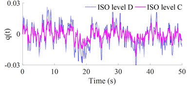
According to the optimization code of the basic genetic algorithm programs in Table 1 [19], an optimal program of the heavy truck dynamic model is developed and applied to find the minimum values of the and . The results of the optimal running process are shown in Fig. 4. The results show that the Minimum fitness values of and are reached from the value 700 of evolutionary generation to the end. Thus, the optimization of the individuals is also obtained at the value 700 of generation. By decoding, the optimized values of the stiffness and damping parameters are presented in Tables 5 and 6. The optimal values of the vehicle dynamic parameters are then used to compute and assess the optimal performance.
Based on the optimal results of vehicle parameters, the simulated results of the vehicle with the optimal parameters are simulated and compared with the original parameters under the same simulation conditions. The acceleration vibrations of the vertical driver’s seat and cab’s pitch angle; and their weighted RMS acceleration responses ( and ) are plotted in Fig. 5 and listed in Table 7. As shown in Figs. 5(a) and (b), the vertical driver’s seat and cab’s pitch angle accelerations with the optimal parameters of heavy trucks are significantly reduced in comparison without optimization. The obtained results in Table 7 showed that the weighted RMS accelerations of the and are significantly reduced by 26.3 % and 35.3 %. According to the standard ISO 2631-1 (Table 1 of Part-1) [16], the driver felt a little not uncomfortable. Thus, the ride comfort of heavy trucks is remarkably improved by the optimization of the vehicle dynamic parameters on ISO lever B. To evaluate the optimal performance of the vehicle dynamic parameters under different simulation conditions, the different road surfaces and speeds are simulated and analyzed below.
Fig. 5Optimal results of the acceleration vibrations of the cab and seat
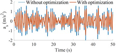
a) Driver’s seat vertical acceleration
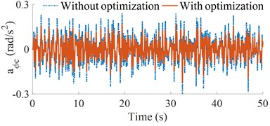
b) Cab pitch acceleration
Table 7The comparison results of the optimal dynamic parameters
Parameter | Without optimization | With optimization | Reduction |
(m/s2) | 0.651 | 0.480 | 26.3 % |
(rad/s2) | 0.085 | 0.055 | 35.3 % |
Fig. 6Result of the weighted RMS accelerations of the cab and seat under various road surfaces
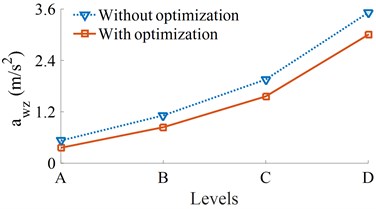
a) Driver’s seat vertical acceleration
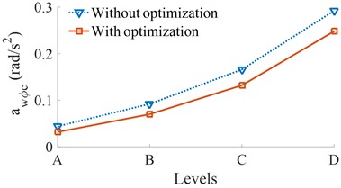
b) Cab pitch acceleration
4.2. The optimal result under various road surfaces
At the speed of the vehicle moving 72 km/h, four different road surface roughness of ISO level A (very good) to ISO level D (poor) have been used to evaluate the effect of road surface roughness on the effectiveness of the optimal parameters. The results of the and are shown in Fig. 6. It can see that all their values are significantly reduced compared to without optimization. Thus, with the optimal parameters, the vehicle ride comfort has been also enhanced under different simulation conditions of the road surfaces.
4.3. The optimal result under various vehicle speeds
The simulation of the vehicle with its optimal parameters over a range of vehicle velocities under the road surface roughness of the level B is plotted in Fig. 7.
Fig. 7Result of the weighted RMS accelerations of the cab and seat under various vehicle speeds
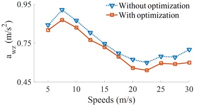
a) Driver’s seat vertical acceleration
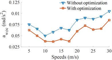
b) Cab pitch acceleration
Figs. 7(a) and (b) show that the and of heavy trucks are significantly reduced in comparison without optimization in all the different speed conditions of heavy trucks. The research result also shows that the speeds of heavy trucks strongly affect the vehicle ride comfort. Within the speed region from 5 m/s to 15 m/s (18 km/h to 54 km/h) of the vehicle traveling, the weighted RMS acceleration of the vertical driver’s seat is strongly increased, while the weighted RMS acceleration of the cab’s pitch angle is minimum. It means that the cab shacking is improved, but the driver ride comfort is increased, thus, the drive feels uncomfortable when the vehicle moving at low speeds.
It is also found that the and are significantly reduced at the speed from 17.5 m/s to 22.5 m/s (63 km/h to 81 km/h). It implied that the ride comfort of heavy trucks is clearly improved. On the contrary, with the increase of accelerations the speeds from 25 m/s to 30 m/s (99 km/h to 108 km/h), all the and are increased, thus, the vehicle ride comfort is reduced. Based on the analysis results, a range of the vehicle speed from 17.5 m/s to 20 m/s (63 km/h to 72 km/h) should be used to more enhance the ride comfort of heavy trucks.
5. Conclusions
Based on the analysis results of the influence of the dynamic parameters of heavy trucks on the ride comfort and the optimal region of the proposed parameters in Part-1, a multi-objective genetic algorithm is developed and applied to optimize the vehicle dynamic parameters. The research results show that the vehicle system with its optimal parameters can enhance the ride comfort under different simulation conditions. Especially, the weighted RMS accelerations of the and are significantly reduced by 26.3 % and 35.3 % under the ISO level B of the road surface.
The research results also noted that a speed region of the vehicle from 17.5 m/s to 20 m/s (63 km/h to 72 km/h) should be used to further enhance the ride comfort of heavy trucks.
This study not only provides a multi-objective optimal method for the parameters of heavy trucks to enhance the ride comfort of heavy trucks but also as the basis for the optimal design of the vehicle structure to improve vehicle stability and safety.
References
-
Li B. 3-D Dynamic Modeling and Simulation of a Multi-Degree of Freedom 3-Axle Rigid Truck. University of Wollongong, New South Wales, Australia, 2006.
-
Jiao R., Nguyen V. Studies on the low frequency vibration of the suspension system for heavy trucks under different operation conditions. Journal of Noise and Vibration Worldwide, 2020, https://doi.org/10.1177/0957456520948271
-
Lu S. Optimum design of “road-friendly” vehicle suspension systems subjected to rough pavement surfaces. Applied Mathematical Modelling, Vol. 26, Issue 5, 2002, p. 635-652.
-
Yong Y., Ren W., Chen L., Jiang M., Yang Y. Study on ride comfort of tractor with tandem suspension based on multi-body system dynamics. Applied Mathematical Modelling, Vol. 33, Issue 1, 2009, p. 11-33.
-
Nguyen V., Jiao R., Zhang J. Control performance of damping and air spring of heavy truck air suspension system with optimal fuzzy control. International Journal of Vehicle Dynamics, Stability, and NVH, Vol. 4, 2020, p. 179-194.
-
Nguyen V., Zhang J., et al. Performance analysis of air suspension system of heavy truck with semi-active fuzzy control. Journal of Southeast University, Vol. 33, 2017, p. 159-165.
-
Guglielmino E., Sireteanu T., Stammers C. W., Ghita G., Giudea M. Semi-active suspension control improved vehicle ride and road friendliness, New York: Springer Publishing Company, 2008.
-
Sy D., et al. A hybrid clustering based fuzzy structure for vibration control - Part 2: An application to semi-active vehicle seat-suspension system. Mechanical Systems and Signal Processing, Vol. 450, 2015, p. 288-301.
-
Michele I., Patrizio T., Mauro M. Development of a heavy truck semi-active suspension control. Control Engineering Practice, Vol. 14, 2006, p. 305-312.
-
Sun Z., Zhang Z., He Y., et al. Research on improving the ride comfort of cab for heavy-duty truck. China Mechanical Engineering, Vol. 15, Issue 17, 2004, p. 1584-1586.
-
Nguyen V., Zhang J., et al. Study of fuzzy control for cab’s isolation system of heavy truck. Vibroengineering Procedia, Vol. 10, 2016, p. 309-314.
-
Chen Y., Zhong L., et al. Hybrid fuzzy skyhook surface control using multi-objective microgenetic algorithm for semi-active vehicle suspension system ride comfort stability analysis. Journal of Dynamic Systems, Measurement, and Control, Vol. 134, 2012, p. 041003.
-
Zhang Z., Lu P. Optimization method of suspension parameters for articulated vehicle based on ride comfort and road -friendliness. Journal of Traffic and Transportation Engineering, Vol. 9, Issue 5, 2009, p. 49-354.
-
Zhang J., He Y., Yang H. Modification of cab suspension system based on pitch angular acceleration. China Mechanical Engineering, Vol. 23, Issue 18, 2012, p. 2258-2262.
-
Mechanical Vibration-Road Surface Profiles - Reporting of Measured Data. ISO 8068, 1995.
-
Mechanical Vibration and Shock-Evaluation of Human Exposure to Whole Body Vibration -Part 1: General Requirements. ISO 2631-1, 1997.
-
Nguyen V., Jian R., et al. Performance analysis of semi-active hydraulic system of the off-road vibratory roller cab using optimal fuzzy-PID control. Journal of Central South University, Vol. 35, 2019, p. 399-407.
-
Nguyen V., Zhang J., Yang X. Low-frequency performance analysis of semi-active cab’s hydraulic mounts of an off-road vibratory roller. Shock and Vibration, Vol. 2019, 2019, p. 8725382.
-
Zadeh N., Salehpour M., Jamali A., Hanghgoo E. Pareto optimization of a five-degree of freedom vehicle vibration model using a MUGA, Engineering Applications of Artificial Intelligence, Vol. 23, Issue 4, 2010, p. 543-551.
About this article

This research was supported by Open Fund Project of Hubei Key Laboratory of Intelligent Transportation Technology and Device, Hubei Polytechnic University, China (No. 2020XY105) and Talent Introduction Fund Project of Hubei Polytechnic University (No. 19XJK17R).
