Abstract
To enhance the ride comfort and improve the road friendliness of the heavy truck, based on the dynamic model of the heavy truck, the semi-active suspension system of the vehicle is proposed and controlled based on the fuzzy logic control and Matlab/Simulink software. The efficiency of the semi-active suspension system is then evaluated based on the indexes of the root mean square acceleration of the driver’s seat, the root mean square acceleration of the cab's pitching angle, and the dynamic load coefficient of the wheel axles. The results show that with the semi-active suspension system of the heavy truck controlled by the fuzzy logic control, the acceleration responses of the heavy truck and the dynamic forces of the wheel axles are greatly reduced in comparison with the passive suspension system under various operating conditions of the loads and speeds. Especially, with the semi-active suspension system controlled by the fuzzy logic control, the root mean square accelerations of the driver’s seat and cab pitch angle; and the dynamic load coefficient at 2nd axle of the wheel are clearly reduced by 23.7 %, 27.2 %, and 20.9 % in comparison with the passive suspension system, respectively. Thus, both ride comfort and road friendliness of the heavy truck are improved by the semi-active suspension system. In addition, the vehicle load insignificantly affects ride comfort. However, it greatly affects the road damage, especially with the half load condition of the vehicle. Thus, to improve road friendliness, the full load condition of the vehicle should be used.
Highlights
- Both the indexes of the ride comfort and road friendliness of the heavy truck have been evaluated under the various operating conditions of the vehicle.
- The fuzzy logic control has been applied to control the heavy truck’s semi-active suspension.
- The research results show that the fuzzy logic control applied to control the semi-active suspension of the heavy truck not only enhances the driver’s ride comfort but also can be applied on the road friendliness under various simulation conditions. This means that the heavy truck’s suspension system should be controlled to enhance the ride comfort and safe movement as well as the road damage.
1. Introduction
One of the most important requirements of heavy vehicles is to improve ride comfort and road friendliness. To solve these problems, the heavy truck’s suspension system ought to be able to isolate the sprung mass from the vibration excitations from the road surface and reduce the dynamic load coefficient (DLC) of the wheel axles under different operation conditions of the vehicle. With the suspension system equipped on the heavy trucks, the passive suspension systems were widely used in heavy vehicles. The air suspension systems, active, and semi-active suspension systems were then studied and applied due to their capabilities of consuming less power, low cost, and providing better ride quality. The studies results showed that the heavy truck’s semi-active suspension systems can improve ride comfort and reduce dynamic tire forces [1-2].
Besides, some control methods including the fuzzy logic control (FLC) [3-4], FLC-skyhook and FLC-PID control [5-6], FLC-, MR fluid damper and Skyhook-NFLC control [7-9] were applied to adjust the damping coefficient of the vehicle’s suspension system. However, the quarter-car dynamic models were used for the most of research. To fully evaluate the performance of the above control methods, the 2D and 3D dynamic models of the vehicles were then studied. Yagiz [10] used a half vehicle with 5-DOF and applied the FLC to control vehicle suspensions and driver’s seat suspension. Yoshimura [11] used a half vehicle with 6-DOF and applied the FLC-Skyhook damper to control active suspensions. Ieluzzi [12] established a half-heavy truck model and also applied the skyhook control in Matlab/Simulink and Adams software to control the suspension system of the tractor driver. In summary, the main goals of these researches are to improve vehicle’s ride comfort.
For the road friendliness of the heavy trucks, Buhari [13] studied the effect of the design parameters of the suspension systems of the heavy truck by comparing the DLC’s value of tire forces at the vehicle axles. The results showed that the DLC’s value was greatly affected by the dynamic parameters of the suspension systems. Xie [14] applied the FLC-PID controller to control semi-active air suspensions of the heavy truck by using the half-vehicle model. The results showed that the dynamic loads at the wheels were significantly improved. However, the above research only evaluated road friendliness. The ride comfort of the heavy truck has not been analyzed.
To fully evaluate the ride comfort and road friendliness of the heavy truck using the semi-active suspension system, this paper proposes a 2D dynamic model with 10-DOF of the heavy truck using the semi-active suspension system controlled by the FLC controller; and the root mean square (RMS) acceleration responses of the vertical driver’s seat, cab pitch angle, as well as the DLC’s value are chosen as objective functions. A fuzzy control programming developed based on Matlab/Simulink software is applied to control the damping coefficients of the suspension system of the heavy truck. The control performance of the semi-active suspension system is then analyzed under different operation conditions of the vehicle.
The main contributions of this paper can be summarized as follows:
1) Both the indexes of the ride comfort and road friendliness of the heavy truck have been evaluated under the various operating conditions of the vehicle.
2) The fuzzy logic control has been applied to control the heavy truck’s semi-active suspension.
3) The research results show that the fuzzy logic control applied to control the semi-active suspension of the heavy truck not only enhances the driver’s ride comfort but also can be applied on the road friendliness under various simulation conditions. This means that the heavy truck’s suspension system should be controlled to enhance the ride comfort and safe movement as well as the road damage.
The remainder of the paper is organized as follows: Section 2 establishes the dynamic models of the heavy truck and the vibration excitation of the road surface. Section 3 designs the fuzzy logic controller for the semi-active suspension of the heavy truck. Section 4 simulates and valuates the efficiency of the semi-active suspension of the vehicle on improving the ride comfort and road friendliness. Section 5 concludes the paper.
2. Model of the heavy truck
2.1. Dynamic model
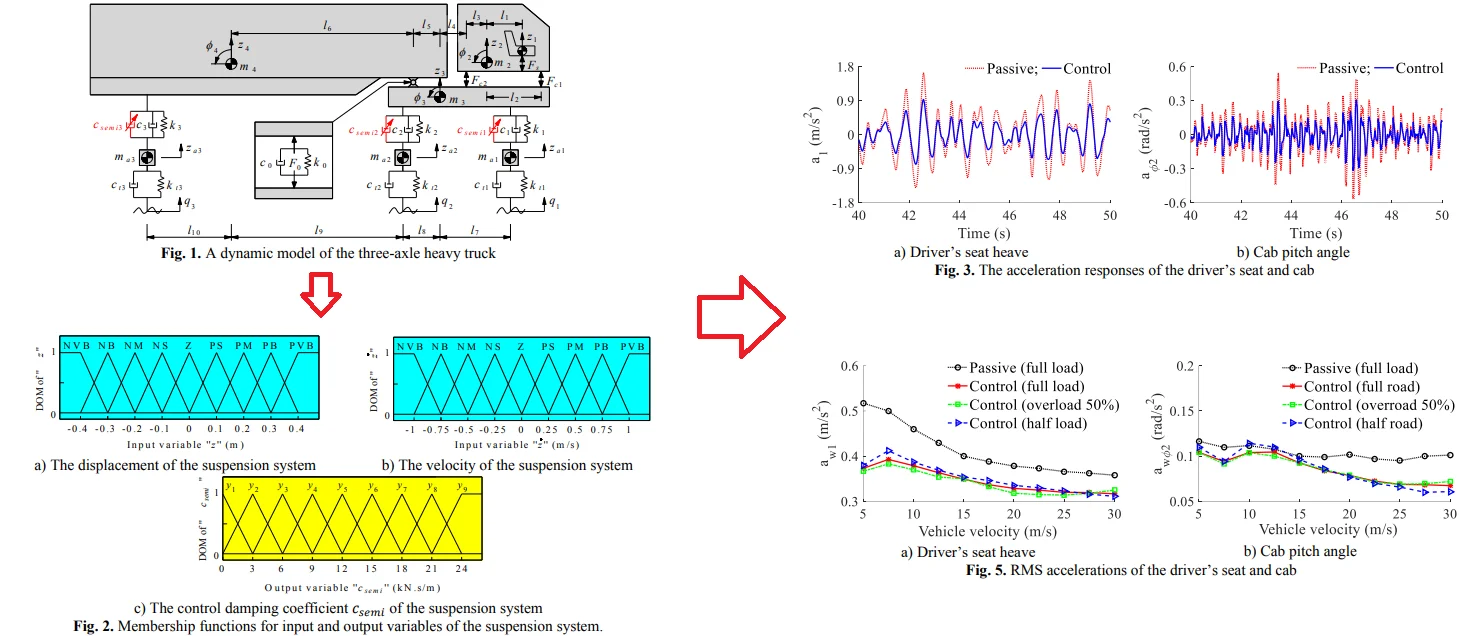
In this study, a three-axle heavy truck with the dependent suspension systems for the steering axle (first axle), the tractor driver axle (second axle), and the trailer axle (third axle) is selected to build the vehicle dynamic model. The 2D dynamic model of the heavy truck with 10-DOF is established to analyze the performance of the semi-active suspension system of the heavy truck, as shown in Fig. 1. Where, , , , , , , and are the vertical displacement of the driver’s seat, the cab, the tractor driver, the trailer, the 1st axle, the 2nd axle, and the 3rd axle, respectively. , , and are the pitch angle of the cab, the tractor driver, and the trailer. , , , , , , and are the mass of the driver’s seat, the cab, the tractor driver, the trailer, the 1st axle, the 2nd axle, and the 3rd axle, respectively. and are the vertical dynamic forces of the suspension systems of the driver’s seat and the cab. is the vertical dynamic force of the articulation connection between the tractor driver and trailer. , , and are the controlled damping coefficient, passive damping coefficient, and stiffness coefficient of the 1st axle, 2nd axle, 3rd axle of the heavy truck. and are the damping and stiffness coefficients of the 1st axle, 2nd axle, 3rd axle of the heavy truck. is the excitations of the road surface roughness at the wheels. is the distances of the vehicle.
Fig. 1A dynamic model of the three-axle heavy truck
Based on the heavy truck’s dynamic model, the motion equations of the driver’s seat, cab, tractor driver, trailer, and axles are given as follows:
The vibration equation of the driver’s seat:
where and are the damping and stiffness parameters of the driver’s seat suspension.
The vibration equations of the cab:
where and are the damping and stiffness parameters at the front and rear suspension of the cab.
The vibration equations of the tractor driver:
where the force responses of the tractor driver’s suspension system ( and ) and force response the articulation connection between the tractor driver and trailer () are determined in Eq. (4), respectively:
The vibration equations of the trailer:
where the force response of the trailer’s suspension system () is determined in Eq. (4):
The vibration equations of the axles:
where the force responses of the axles (, , ) are determined in Eq. (8):
2.2. Vibration excitation of the road surface roughness
The road surface with a high degree of roughness is a random excitation of the vehicle, which impacts not only the vehicle-road interaction but also the vehicle’s ride comfort. The random excitation of the road surface roughness can be represented by a randomly modulated periodic. The general form of the displacement power spectral density (PSD) of the road surface roughness is determined by the experimental formula [20]:
where is the space frequency; is the reference space frequency, 0.1 m-1; is the road surface roughness coefficient or PSD of the road surface under the reference space frequency ; is the frequency index which determines the frequency configuration of the PSD of the road surface ( 2 rad/s). Road surface roughness is assumed to be a zero-mean stationary Gaussian random process. It can be generated through the Fourier transformation as:
where is the random phase uniformly distributed from 0 to 2.
According to ISO 8068 [20], the road surface roughness is established in this study.
3. Control of the semi-active suspension system using the fuzzy logic control
The fuzzy logic control (FLC) was incepted by Zadeh in 1965. It is then widely applied in a variety of situations as well as diverse fields. To control the semi-active suspension system of the heavy truck, three passive suspension systems should be controlled separately. Thus, three different fuzzy controls should be designed. However, the design process of these fuzzy controls is the same, thus a specific fuzzy control is designed to control the suspension system.
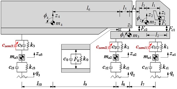
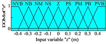
The FLC consists of a fuzzification interface, a fuzzy inference system, and a defuzzification interface. First, the crisp values in fuzzification are transformed into linguistic variables. The fuzzy inference system is then used by the fuzzy rule in accordance with the inference rule. Finally, the linguistic variables are transformed back to crisp values through defuzzification for use by the physical plant of the suspension system [3-4]. In this study, the relative displacement and the relative velocity of the suspension system are considered as two input variables, while the damping coefficient is the output of the FLC.
The nine linguistic variables of input and output variables are defined, such as the positive very big (PVB), positive big (PB), positive medium (PM), positive small (PS), zero (Z), negative small (NS), negative medium (NM), negative big (NB), negative very big (NVB) and (1, 2,.., 9).
The membership functions for input and output variables of the semi-active suspension system are represented by a fuzzy set. The shape of membership functions is the triangular function and the value of the degree of memberships (DOM) is between 0 and 1, as shown in Fig. 3.
Fig. 2Membership functions for input and output variables of the suspension system.
a) The displacement of the suspension system
b) The velocity of the suspension system
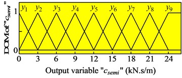
c) The control damping coefficient of the suspension system
Table 1Rules for fuzzy control
NVB | NB | NM | NS | Z | PS | PM | PB | PVB | ||
NVB | ||||||||||
NB | ||||||||||
NM | ||||||||||
NS | ||||||||||
Z | ||||||||||
PS | ||||||||||
PM | ||||||||||
PB | ||||||||||
PVB | ||||||||||
In the fuzzy logic control, the control rules of “If-then” are applied to describe the relationship between , , and according to the designers’ knowledge and experience. The control rules of the fuzzy logic control are given in Table 1. Based these control rules, the eighty-one control rules of “If-then” are described as follows:
(1) If is NVB andis NVB then is ,
(2) If is NB andis NVB then is ,
...
(81) If is PVB andis PVB then is .
The fuzzy inference system is selected by the minimum function and the centroid method of Mamdani [16-17]. In this paper, the fuzzy inference system of Mamdani is used to control the active damping coefficient of the suspension system model.
4. Evaluating the efficiency of the seni-active suspension system
4.1. The index of the ride comfort
According to the ISO 2631-1 [18], the effect of vibration on the driver’s ride comfort is evaluated based on the root mean square (RMS) acceleration responses of the driver’s seat and cab’s pitch angle defined by:
where is the simulation time.
The RMS accelerations of the vertical driver’s seat and cab pitch angle are then used to evaluate the vehicle’s ride comfort. The smaller values of the and mean that the ride comfort of the heavy truck is better.
4.2. The index of the road friendliness
The dynamic load coefficient (DLC) is frequently used to characterize the dynamic loading of the axles and it is defined by a ratio of the RMS of the dynamic load fluctuation over static load [13]:
were is the RMS of the vertical dynamic wheel load, and is the average or nominal static vertical wheel load.
The DLC’s value is in the range of 0.05 to 0.3 under normal operating conditions. The DLC’s value can reduce to zero when the wheel moves on a special smooth road or increases up to 0.4 when the wheel-road contact is broken [19]. In this study, the dynamic load coefficient is used to analyze the road friendliness of the heavy truck. The smaller value of the DLC means that the road friendliness of the heavy truck is better.
5. Results and analysis
The main objective of this study is to analyze the performance of the semi-active suspension system in improving the ride comfort and road friendliness of heavy truck under different operation conditions. With the dynamic parameters of a heavy truck in its fully load condition listed in Table 2, Matlab/ Simulink software is used to simulate and calculate the results.
Table 2Dynamic parameters of the heavy truck
Parameter | Value | Parameter | Value |
(kg) | 85 | (m) | 4.1, 4.0 |
(kg) | 500 | (N/m) | 2.32×10⁶ |
(kg) | 3600 | (N/m) | 8.60×10⁶ |
(kg) | 12500 | (N/m) | 2.00×10⁶ |
(kg) | 270.1 | (Ns/m) | 2.20×10³ |
(kg) | 520.4 | (Ns/m) | 10.0×10³ |
(kg) | 340.0 | (Ns/m) | 84.0×10³ |
(m) | 0.2 | (N/m) | 20.0×10⁶ |
(m) | 1.2 | (Ns/m) | 200×103 |
(m) | 0.8 | (N/m) | 1.03×10⁶ |
(m) | 0.4 | (N/m) | 2.06×10⁶ |
(m) | 0.5 | (N/m) | 2.06×10⁶ |
(m) | 6.9 | (Ns/m) | 3.00×10³ |
(m) | 2.2 | (Ns/m) | 3.00×10³ |
(m) | 1.0 | (Ns/m) | 3.00×10³ |
5.1. Simulation of the semi-active suspension system
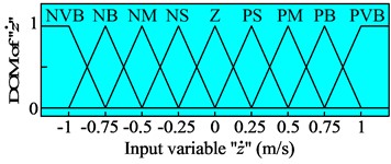
To control the semi-active suspension system of the heavy truck using the FLC, the simulation is carried out when the vehicle is moving on the road surface roughness of ISO level B at 20 m/s. The simulation results of the acceleration responses of the driver’s seat and cab pitch angle are shown in Fig. 3. Besides, based on the acceleration response of the driver’s seat and cab in Fig. 3, the calculation results of the and in Eq. (11) are then listed in Table 3.
With the semi-active suspension systems of the heavy truck controlled by the FLC, the simulation results in Figs. 4(a-b) show that the acceleration responses of the driver’s seat and cab pitch angle are greatly reduced in comparison with the passive suspension system. The results in Table 3 show that the RMS values of the driver’s seat and cab pitch angle are significantly reduced by 23.7 % and 27.2 %, respectively. Therefore, the ride comfort of the heavy truck has been greatly improved in comparison without the control.
Table 3Control performance with fuzzy control
Parameters | Passive | Control | Reduction (%) |
(m/s2) | 0.422 | 0.322 | 23.7 |
(rad/s2) | 0.101 | 0.073 | 27.2 |
DLC2nd axle | 0.091 | 0.072 | 20.9 |
Fig. 3The acceleration responses of the driver’s seat and cab
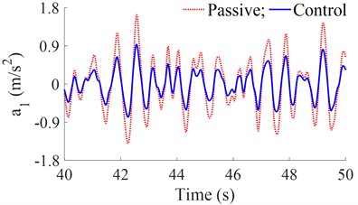
a) Driver’s seat heave
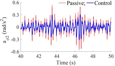
b) Cab pitch angle
Besides, the dynamic force of the second axle and the RMS values of the dynamic forces of the first, second, and third axle are calculated and plotted in Fig. 4(a) and 4(b).
Fig. 4The dynamic force responses of the wheel axles
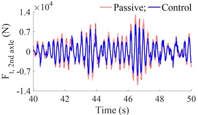
a) Dynamic force at second axle
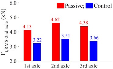
b) RMS value of dynamic forces of all the axles
The results show that the RMS values of the dynamic forces at all the first, second, and third axles of the heavy truck using the control are lower than that of the passive suspension system. In addition, Fig. 4(b) shows that the RMS value of the dynamic force at the second axle is higher than that of the first and third ones. This means that the wheels at the second axle greatly affect the road damage. Therefore, the DLC of the second axle is used to evaluate the road friendliness and the control performance of the FLC. Besides, the calculation result of the DLC2nd axle is also listed in the same Table 3. The DLC2nd axle of the vehicle suspension with the control is strongly reduced by 20.9 % in comparison with the passive suspension. Thus, the road friendliness of the heavy truck with the control is improved.
5.2. Influence of the velocity and load of the vehicle
A range of the vehicle velocities under different loading conditions of half load, full load, and overload of the vehicle is simulated to analyze the performance of the semi-active suspension system. The results of the RMS accelerations of the driver’s seat and cab pitch angle are plotted in Fig. 5(a) and 5(b).
Figs. 5(a-b) show that the RMS accelerations of the driver’s seat and cab pitch angle with the control are significantly decreased in comparison with the passive suspension system under different loading conditions. This means that the ride comfort of the vehicle using the control is improved under the different operating conditions of the vehicle including the change of the vehicle loads and velocities. Besides, the dynamic force and DLC value of the second axle under the different operating conditions are also shown in Figs. 6(a-b).
Fig. 5RMS accelerations of the driver’s seat and cab
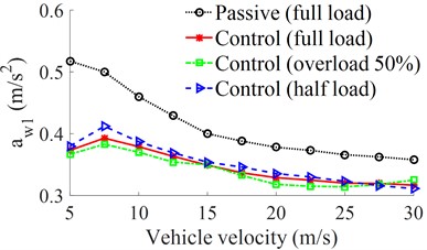
a) Driver’s seat heave
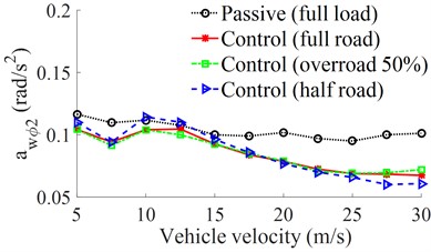
b) Cab pitch angle
Fig. 6The DLC’s values on the second axle of the tractor driver
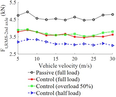
a) Dynamic force at the second axle
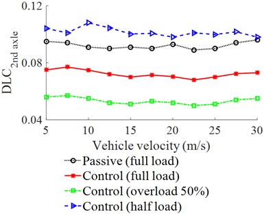
b) DLC value at the second axle
Fig. 6(a) indicates that the vehicle speed insignificantly affects the dynamic force of the second axle. Conversely, the vehicle load greatly affects the dynamic force of the second axle. In the condition of the half load of the vehicle, the dynamic force is the smallest while the dynamic force of the full load and overload 50 % are the same. However, with the suspension system controlled by the FLC, the dynamic force of the second axle is greatly reduced in comparison with the passive suspension system. Conversely, with the result of the dynamic force of the second axle in Fig. 6(a), their DLC values in Fig. 6(b) are greatly changed and affected by the change in the vehicle loads. In the half load condition, the DLC value is the highest, this means that the second axle of the wheel greatly affects the road friendliness in the condition of the half load of the vehicle. Therefore, the vehicle should use the full load to reduce the road damage. In the full load condition of the vehicle, the DLC’s value with the semi-active suspension system is significantly reduced in comparison with the passive suspension system. Thus, the road friendliness of the heavy truck is improved by the suspension system using the control.
6. Conclusions
With the semi-active suspension system of the heavy truck controlled by the FLC, the acceleration responses of the driver’s seat and cab pitch angle as well as the dynamic forces of the wheel axles are greatly reduced in comparison with the passive suspension system. Especially, the values of the , , and DLC2nd axle are clearly reduced by 23.7 %, 27.2 %, and 20.9 %, respectively. Thus, both ride comfort and road friendliness of the heavy truck are improved.
Under the different load and speed conditions, using the semi-active suspension system, both ride comfort and road friendliness are also improved under the change of load and speed. In addition, the vehicle load insignificantly affects ride comfort. However, it greatly affects the road damage, especially with the half load condition of the vehicle. Thus, to improve road friendliness, the full load condition of the vehicle should be used.
References
-
E. Guglielmino, K. Edge, and C. Stammers, “Robust force control in electrohydraulic friction damper systems using a variable structure scheme with non-linear state feedback,” in Internationales Fluidtechnisches Kolloquium, pp. 163–176, 2000.
-
S.-B. Choi, S.-K. Lee, and Y.-P. Park, “A hysteresis model for the field-dependent damping force of a magnetorheological damper,” Journal of Sound and Vibration, Vol. 245, No. 2, pp. 375–383, Aug. 2001, https://doi.org/10.1006/jsvi.2000.3539
-
M. V. C. Rao and V. Prahlad, “A tunable fuzzy logic controller for vehicle-active suspension systems,” Fuzzy Sets and Systems, Vol. 85, No. 1, pp. 11–21, Jan. 1997, https://doi.org/10.1016/0165-0114(95)00369-x
-
E. H. Mamdani and S. Assilian, “An experiment in linguistic synthesis with a fuzzy logic controller,” International Journal of Man-Machine Studies, Elsevier BV, 1975.
-
R. Pekgökgöz, M. A. Gürel, M. Bilgehan, and M. Kısa, “Active suspension of cars using fuzzy logic controller optimized by genetic algorithm,” International Journal of Engineering and Applied Sciences, Vol. 2, No. 4, pp. 27–37, 2010.
-
Y. Chen, Z.-L. Wang, J. Qiu, and H.-Z. Huang, “Hybrid fuzzy skyhook surface control using multi-objective microgenetic algorithm for semi-active vehicle suspension system ride comfort stability analysis,” Journal of Dynamic Systems, Measurement, and Control, Vol. 134, No. 4, p. 04100, Jul. 2012, https://doi.org/10.1115/1.4006220
-
L. C. Félix-Herrán, D. Mehdi, J. J. Rodríguez-Ortiz, R. Soto, and R. Ramírez-Mendoza, “H∞ control of a suspension with a magnetorheological damper,” International Journal of Control, Vol. 85, No. 8, pp. 1026–1038, Aug. 2012, https://doi.org/10.1080/00207179.2012.674216
-
L. Zhang, V. Nguyen, C. Wang, S. Xu, and H. Li, “Review research on isolation systems of the cab and driver’s seat in soil compactors,” SAE International Journal of Vehicle Dynamics, Stability, and NVH, Vol. 7, No. 2, pp. 1–22, Jan. 2023, https://doi.org/10.4271/10-07-02-0008
-
C. Li and Q. Zhao, “Fuzzy control of vehicle semi-active suspension with MR damper,” in 2010 WASE International Conference on Information Engineering (ICIE 2010), Vol. 10, pp. 426–428, Aug. 2010, https://doi.org/10.1109/icie.2010.279
-
N. Yagiz, L. E. Sakman, and R. Guclu, “Different control applications on a vehicle using fuzzy logic control,” Sadhana, Vol. 33, No. 1, pp. 15–25, Feb. 2008, https://doi.org/10.1007/s12046-008-0002-9
-
T. Yoshimura, Y. Isari, Q. Li, and J. Hino, “Active suspension of motor coaches using skyhook damper and fuzzy logic control,” Control Engineering Practice, Vol. 5, No. 2, pp. 175–184, Feb. 1997, https://doi.org/10.1016/s0967-0661(97)00224-4
-
M. Leluzzi, P. Turco, and M. Montiglio, “Development of a heavy truck semi-active suspension control,” Control Engineering Practice, Vol. 14, No. 3, pp. 305–312, 2005, https://doi.org/10.1016/j.conengprac
-
R. Buhari, M. Rohani, and M. Abdullah, “Dynamic load coefficient of tyre forces from truck axles,” Applied Mechanics and Materials, Vol. 405-408, pp. 1900–1911, 2013, https://doi.org/10.4028/www
-
Z. Xie, P. K. Wong, J. Zhao, T. Xu, K. I. Wong, and H. C. Wong, “A noise-insensitive semi-active air suspension for heavy-duty vehicles with an integrated fuzzy-wheelbase preview control,” Mathematical Problems in Engineering, Vol. 2013, pp. 1–12, 2013, https://doi.org/10.1155/2013/121953
-
M. N. Fox, R. L. Roebuck, and D. Cebon, “Modelling rolling-lobe air springs,” International Journal of Heavy Vehicle Systems, Vol. 14, No. 3, p. 254, 2007, https://doi.org/10.1504/ijhvs.2007.015603
-
F. Karray, “Soft Computing and Intelligent Systems Design, Theory, Tools and Applications,” IEEE Transactions on Neural Networks, 2004.
-
E. H. Mamdani, “Advances in the linguistic synthesis of fuzzy controllers,” International Journal of Man-Machine Studies, Vol. 8, No. 6, pp. 669–678, Nov. 1976, https://doi.org/10.1016/s0020-7373(76)80028-4
-
“Iso 2631-1. Mechanical vibration and shock-evaluation of human exposure to whole-body vibration – Part 1,” Switzerland, 1997.
-
D. Cole and D. Cebon, “Truck suspension design to minimize road damage,” Proceedings of the Institution of Mechanical Engineers, Part D: Journal of Automobile Engineering, Vol. 210, No. 2, pp. 95–107, 1996.
-
Iso 8068., “ISO 8068. Mechanical vibration-road surface profiles-reporting of measured data,” Switzerland, 1995.
-
G. Tsampardoukas, C. W. Stammers, and E. Guglielmino, “Hybrid balance control of a magnetorheological truck suspension,” Journal of Sound and Vibration, Vol. 317, No. 3-5, pp. 514–536, Nov. 2008, https://doi.org/10.1016/j.jsv.2008.03.040
Cited by
About this article

This study is supported by the Key Scientific Research Project of Hubei Polytechnic University (No. 22xjz02A).
The datasets generated during and/or analyzed during the current study are available from the corresponding author on reasonable request.
The authors declare that they have no conflict of interest.
