Abstract
To evaluate the acceleration-frequency characteristics of the suspension system of the heavy vehicles, a nonlinear dynamic model of two-axle heavy vehicles is established. A calculation method based on the complex domain is applied to solve the vibration equations of the heavy vehicle in the frequency domain instead of the traditional time domain. Matlab software is then used to calculate the vibration equations under various operating conditions. The research results show that the resonant frequency of the suspension system is not affected by the vehicle speed and the road surface, while it is clearly influenced by the weight of the vehicle and the stiffness of the suspension system. However, the acceleration-frequency characteristics of the vertical vehicle body, pitching vehicle body, and vertical front/read axles are greatly influenced under various operating conditions, especially at the high speed 30 m.s-1, a wavelength of the road surface 6 m, and 80 % of the vehicle load.
Highlights
- A calculation method based on the complex domain is applied to solve the vibration equations of the heavy vehicle.
- The resonant frequencies of the suspension system are not affected by the vehicle speed and the wavelength of the road surface.
- The amplitude of the acceleration-frequency characteristic is increased with increasing the vehicle speed and reducing the wavelength of the road surface, thus the vehicle ride comfort and safety of the suspension system are reduced.
- Both the resonant frequency and amplitude of the acceleration-frequency characteristic are strongly influenced by the weight of the vehicle and the stiffness of the suspension system.
1. Introduction
The suspension system of the heavy vehicles not only reduces the transmission vibration from the road surface to the body and cabin of the operator; but also has the effect of reducing the dynamic load of the wheels on the road surface to increase the road friendliness of the heavy trucks [1-4]. In the design studies of the suspension system, the ride comfort, suspension deformation, and road friendliness are three main indexes to evaluate the performance of the suspension system [5-7]. To achieve the goal of the ride comfort, the optimal design and control of the suspension system had been researched and developed [4, 8-11]. Besides, to improve the road friendliness, the air suspension systems had been studied for the heavy trucks [2, 12, 13]. The suspension systems were also controlled to improve the ride comfort performance of the heavy vehicles [2, 5]. However, in the existed studies, the vibration equations of the vehicle and suspension systems were mainly simulated and calculated in the time domain.
One of the important factors for vehicle suspension design was to consider the specific vibration frequency of the suspension system to avoid the resonance of the suspension system under the excitation frequency of the road surface [6, 7, 10]. Some studies of the ride comfort of the vehicle in the frequency domain had shown that the ride quality of the vehicle and durability of the suspension structures were greatly affected in the frequency range below 10 Hz, especially in the low-frequency range from 0.5-4 Hz [14, 15]. To reduce the impact of the resonant in the low-frequency region, the specific vibration frequency of the suspension system should be calculated and designed in a range below 2.5 Hz [16]. However, the specific vibration frequency of the suspension system depended not only on its stiffness but also on the weight of the vehicle. In actual operating conditions, the weight of the vehicle could be changed and depended on the load of the vehicle (half loading, fully loading, or over loading) [5, 17]. Thus, the specific vibration frequency of the suspension system was also changed. Under the various excitation frequencies of the road surface, it could lead to vibration resonance for the suspension system, causing instability and reducing durability for the system elements. Thus, it is necessary to study the effect of working conditions on the frequency amplitude characteristics of the suspension system in the low-frequency region.
In this study, a nonlinear dynamic model of two-axle heavy vehicle with four degrees of freedom is established to analyze the acceleration-frequency characteristics of the suspension system in the low-frequency domain. A calculation method based on the complex domain is applied to solve the vibration equations of the heavy vehicle in the frequency domain instead of the traditional time domain. The vehicle speed, loading vehicle, wavelength of the road surface, and stiffness of the suspension system are then simulated to analyze the result.
2. Materials and methods
2.1. Heavy vehicle dynamic model
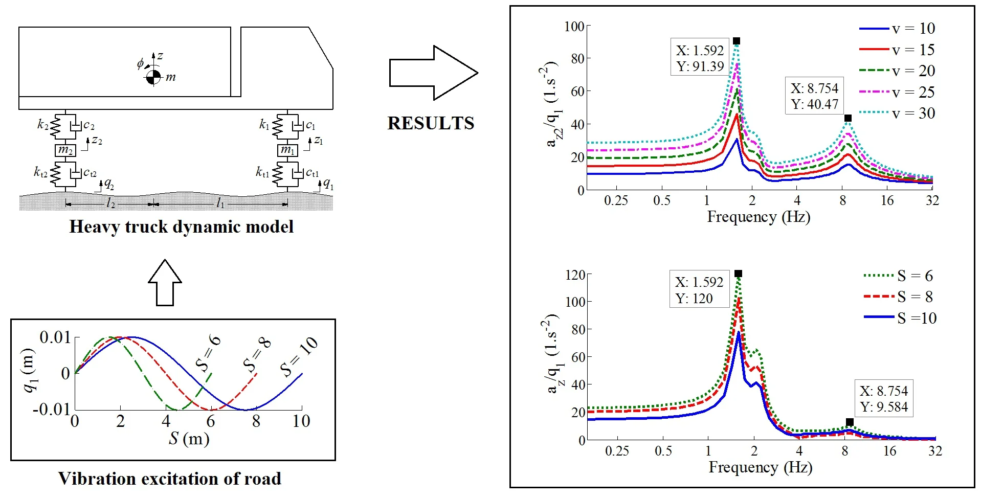
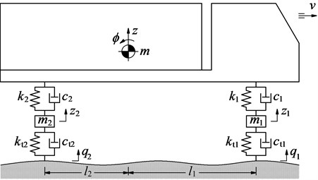
Based on the actual structure of the heavy vehicles, the front and rear suspension systems of the vehicle are equipped with the dependent suspension systems. Thus, a nonlinear dynamic model of two-axle vehicle with four degrees of freedom is established to analyze the low-frequency characteristic of the suspension system. The vehicle model is plotted as in Fig. 1, where , , and are the lumped mass at the centre of gravity of the vehicle body, front axle, and rear axle; , , and are the vertical displacements at the centre of gravity of the vehicle body, front axle, and rear axle, respectively; is the angular displacement at the centre of gravity of the vehicle body; and are the damping parameters of the front/rear suspension systems and front/rear wheels; and are also the stiffness parameters of the front/rear suspension systems and front/rear wheels; and are the distances from the centre of gravity of the vehicle body to the contact points of the front/rear wheels in the horizontal direction.
Fig. 1The lumped parameter model of the heavy vehicle
Based on the heavy vehicle dynamic model and by applying Newton’s second law, the different dynamic equations of the heavy vehicle are given as follows:
In previous studies on the vehicle vibration, most studies were based on the vehicle dynamic models and then set the vibration equation in the time domain to study and optimize the vehicle’s structure and suspension system [2-4, 13]. In this study, the low-frequency characteristic of the vehicle suspension system under the various operating conditions is the research goal. Thus, the vibration equation of the heavy vehicle calculated in the frequency domain is chosen to analyze the results.
2.2. Solving the vibration equations in the frequency domain
To study the amplitude-frequency characteristic of the vehicle vibration, it is necessary to use the transfer function. To convert the unknown of the differential equation to the image function, a variable is used to convert the differential equation to the form of the numerical equation with the unknown function as the transfer function. The numerical equation is then solved to find the Laplace transfer function. The frequency transfer function is obtained by replacing s in the Laplace transfer function with . Herein is the excitation frequency.
Based on the Laplace operator, assuming that with the variable is the original function, and it is continuous on the range of [, ] with , then the image of through the Laplace transformation is defined as follows:
According to the theory of the original function [16], the derivative of is also the original function and we have:
In this study, it is assumed that the vertical displacements and velocities at the centre of gravity of the vehicle body, front axle, and rear axle are equal to zero at the time of 0. Therefore, based on Eq. (3), the unknowns of the differential equations in Eq. (1) is written by:
Therefore, Eq. (1) is described via the Laplace transformation as follows:
where and .
By replacing and into Eq. (5), Eq. (5) is then rewritten as follows:
where:
By dividing the two sides of Eq. (6) by the excitation of the front wheel , Eq. (6) is then rewritten in the form of a matrix as follows:
where, , , and are the transfer functions of the vibrations from the road surface at the front axle to the vertical vehicle, to the pitching vehicle angle, to the front axle, and to the rear axle of the vehicle, respectively.
The calculated results obtained by in Eq. (7) have complex number values as follows, (, , , and ):
The absolute value of is the expression that expresses the relationship of the amplitude and excitation frequency , and it determined by the formula:
The relationship between the acceleration amplitude and excitation frequency is determined by the formula:
2.3. Vibration excitation of the heavy trucks
The harmonic function of the road profile is usually described by the sine or cosine functions. The height of the road surface from 10 to 12 mm and the wavelength of the road surface from 5 to 10 m often appear on the asphalt road [16, 18-19]. This type of road profile often causes resonant vibrations. Therefore, the harmonic function of the road profile has been used for evaluating the ride comfort [19], researching the structural parameters of the suspension system and tires, and controlling the vehicle suspension system [10, 20].
In the actual condition, the excitation of the pavement is diverse such as the random, harmonic, or step excitations, etc., it does not exist a type of vibration excitation. However, with the goal of low-frequency vibration analysis of heavy trucks suspension system under various operating conditions, the harmonic function of the road profile is chosen for simulation and analysis of the results. The harmonic function of the road surface is performed in the time domain as follows (Fig. 2(a)):
where , , and are the height of the road surface, frequency, and cycle of the vibration excitation of the road surface, respectively.
Assuming that the wavelength and frequency of the road surface are and , the harmonic function is performed according to the length of the road as (Fig. 2(b)):
When the vehicle travels on the road with a constant speed , we have . Therefore, the relationship between the time and length of the road of the road profile is and . The excitation frequency in Eq. (11) is calculated by , and the harmonic function of the road profile is rewritten as follows:
The distance between the front and rear wheels is , thus, the excitation of the rear wheel performed via the front wheel is:
Eqs. (13) and (14) are the vibration excitation of the front and rear wheels.
Based on the ratio of , and its Laplace transformation, the ratio of the vibration excitation in Eq. (7) written in complex number domain as follows:
Based on the ratio of the vibration excitation in Eq. (15) and the heavy truck’s parameters, as listed in Table 1, Eqs. (7) and (10) are then calculated in the complex number domain to evaluate the acceleration-frequency response of the vehicle suspension system.
Fig. 2The harmonic profile of the road surface excitation
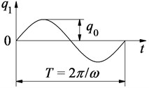
a) On the time
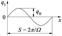
b) On the length of the road
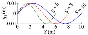
c) Three types of wavelength of road
3. Result and discussion
3.1. Influence of the vehicle velocity
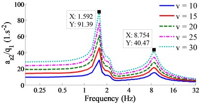
Based on the parameters of the heavy vehicle, as listed in Table 1, the different equations described in the complex number domain are calculated based on Matlab R2010a software under a road surface excitation of harmonic function with 8 m and 0.01 m. To evaluate the acceleration-frequency response of vehicle under various speeds, the vehicle speed of {10, 15, 20, 25, 30} m.s-1 is then chosen. The simulation results are shown in Fig. 3.
The results show that the resonant frequencies appear at low frequencies of 1.592 and 2.228 Hz; and at the high frequency of 8.754 Hz of the suspension system. These resonant frequencies are virtually unchanged under different vehicle speeds of the vehicle. However, the acceleration-frequency characteristics at these resonant frequencies are greatly affected by the vehicle speed. The acceleration-frequency values of the vertical vehicle body, pitching vehicle body, and vertical front/read axles are quickly enhanced by increasing the vehicle speed. This means when the vehicle travels at a high speed on this road surface, the vehicle ride comfort and safety of suspension structure are significantly reduced.
Table 1The simulation parameters of the heavy vehicle
Parameter | Value | Parameter | Value | Parameter | Value |
/ kg | 22 150 | / N.m-1 | 745 000 | / N s.m-1 | 5 100 |
/ kg | 480 | / N.m-1 | 2 247 500 | / N s.m-1 | 1 000 |
/ kg | 1 820 | / N.m-1 | 680 000 | / N s.m-1 | 4 000 |
/ kg.m2 | 18 761 | / N.m-1 | 3 200 000 | / N s.m-1 | 20 000 |
/ m | 2.89 | /m | 0.96 | /m | 0.01 |
Fig. 3Result of the acceleration-frequency responses under the various vehicle velocities.
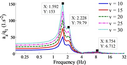
a) Vertical vehicle body
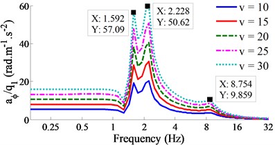
b) Pitching vehicle body
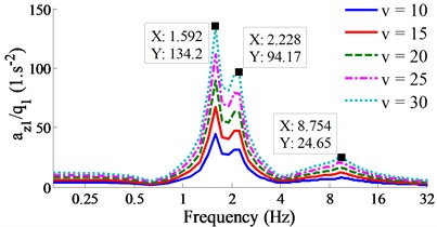
c) Vertical front axle
d) Vertical rear axle
3.2. Influence of the wavelength of the road surface
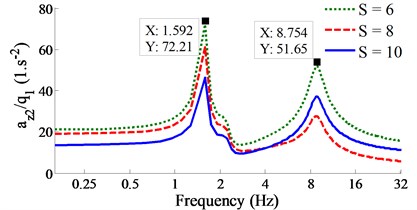
Three types of the wavelength of the road surface of {6, 8, 10} m with the high road surface of 0.01 m plotted in Fig. 2(c) are chosen to simulate under the vehicle speed of 20 m.s-1. The simulation results are plotted in Fig. 4.
Observing Fig. 4, it can see that the resonant frequencies of the vertical vehicle body, pitching vehicle body, and vertical front/read axles are unchanged in comparison with the case of the influence of the various vehicle speeds, these resonant frequencies also appear at low frequencies of 1.592 and 2.228 Hz; and at high frequency of 8.754 Hz of the suspension system. Therefore, the wavelength excitation of the road surface also does not affect the resonant frequency of the vehicle suspension system. However, the acceleration-frequency values of all the vertical vehicle body, pitching vehicle body, and vertical front/read axles are remarkably changed by the wavelength of the road surface of . When the wavelength of the road surface is increased, especially the results of the acceleration-frequency responses with 10 m, it means that the road surface becomes smoother. Therefore, acceleration-frequency values are reduced. The vehicle ride comfort and safety of suspension structure are improved.
Fig. 4Result of the acceleration-frequency responses under the various wavelengths of the road surface.
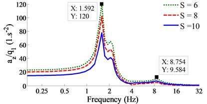
a) Vertical vehicle body
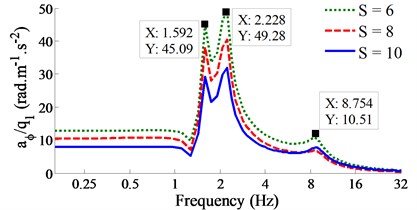
b) Pitching vehicle body
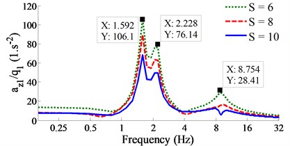
c) Vertical front axle
d) Vertical rear axle
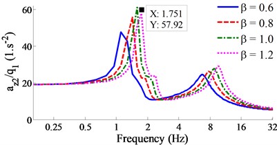
Fig. 5Result of the acceleration-frequency responses under the various vehicle loads
a) Vertical vehicle body
b) Pitching vehicle body
c) Vertical front axle
d) Vertical rear axle
3.3. Influence of the loading vehicle conditions
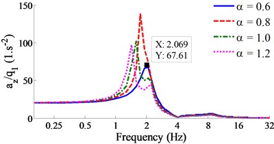
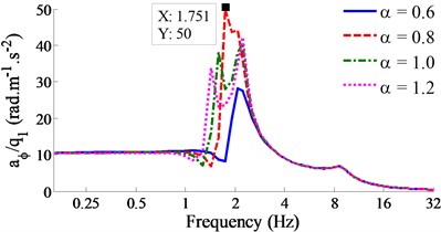
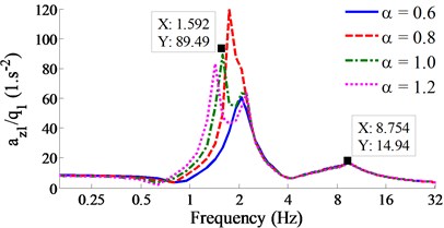
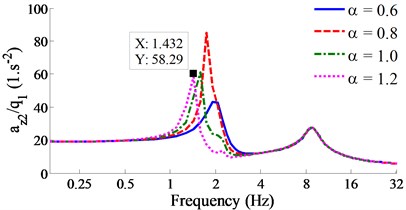
The resonant frequency of the suspension system is determined by the formula of . Therefore, the weight of the vehicle and the stiffness of the suspension system are two important indexes when calculating and designing the suspension system of the vehicle. Under input simulation parameters of 8 m, 0.01 m, and 20 m/s, the loading vehicle conditions chosen by {60 %, 80 %, 100 %, 120 %} of the fully loading vehicle are simulated, and their results are shown in Fig. 5.
The results show that the weight of the vehicle clearly affects the resonant frequency of the suspension system in the low-frequency region. All the resonant frequencies of the vertical vehicle body, pitching vehicle body, and vertical front/read axles appear at 2.069 Hz with 0.6, at 1.751 Hz with 0.8, at 1.592 Hz with 1.0, and at 1.432 Hz with 1.2. It means that when increasing the loading vehicle, the resonant frequency of the suspension system is reduced. At the high-frequency region, the resonant frequency is insignificantly affected by the loading vehicle, it only appears at 8.754 Hz.
Also, in the low-frequency region, the results in Fig. 5 show that the acceleration-frequency characteristics of the vertical vehicle body, pitching vehicle body, and vertical front/read axles are greatly influenced by the loading vehicle conditions. The acceleration-frequency values are greatly enhanced at 0.8. Therefore, this load should be avoided to reduce the amplitude of the acceleration-frequency responses to improve the vehicle ride comfort.
Fig. 6Result of the acceleration-frequency responses under the various stiffness coefficient
a) Vertical vehicle body
b) Pitching vehicle body
c) Vertical front axle
d) Vertical rear axle
3.4. Influence of the stiffness coefficient of the suspension system
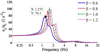
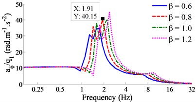
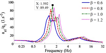
Similarly, under input simulation parameters of 8 m, 0.01 m, and 20 m/s, the stiffness of the suspension system is chosen by {60 %, 80 %, 100 %, 120 %} of the actual stiffness to evaluate the acceleration-frequency characteristics of the vehicle suspension system. The simulation results are plotted in Fig. 6.
Observing the results in Fig. 6, it can see that the resonant frequencies in both low- and high-frequency domains are influenced by the stiffness of the suspension system. Especially at the low-frequency domain, all the resonant frequencies of the vertical vehicle body, pitching vehicle body, and vertical front/read axles also appear at 1.273 Hz with 0.6, at 1.91 Hz with 0.8, at 1.592 Hz with 1.0, and at 1.751 Hz with 1.2. It means that the resonant frequency is enhanced by increasing the stiffness of the suspension system. Besides, the amplitude of the acceleration-frequency responses is increased when increasing the stiffness of the suspensions. Thus, it is concluded that the stiffness of the suspension system affects not only the resonant frequency but also the amplitude of the acceleration-frequency characteristic of the system.
4. Conclusions
In this study, a nonlinear dynamic model of heavy vehicles is established to analyze the acceleration-frequency characteristics of the vehicle suspension system under various operating conditions. The research results can be summarized as follows:
1) A calculation method based on the complex domain is applied to solve the vibration equations of the heavy vehicle in the frequency domain instead of the traditional time domain to analyze the acceleration-frequency characteristic of the vehicle suspension system.
2) The resonant frequencies of the suspension system are not affected by the vehicle speed and the wavelength of the road surface. However, the amplitude of the acceleration-frequency characteristic is increased with increasing the vehicle speed and reducing the wavelength of the road surface, thus the vehicle ride comfort and safety of the suspension system are reduced. To solve this issue, road surface quality has been researched to enhance the pavement smoothness [21-23].
3) Both the resonant frequency and amplitude of the acceleration-frequency characteristic are strongly influenced by the weight of the vehicle and the stiffness of the suspension system. In the design of the vehicle suspension system, the resonance frequency has been concerned. However, in actual working conditions, the load of heavy vehicles is always changed. Thus, the resonant frequency is also changed. To enhance the vehicle ride comfort and safety of the suspension system, the suspension system of the heavy vehicles are being replaced by using the pneumatic suspension system [2, 6] or the semi-active suspension system [5, 7] to control the resonant frequency and reduce the amplitude of the acceleration-frequency response.
References
-
Nguyen V., Zhang J., et al. Effect of the off-road terrains on the ride comfort of construction vehicles. Journal of Southeast University (English Edition), Vol. 35, Issue 2, 2019, p. 191-197.
-
Xie Z., Wong K., Jing Z., et al. A noise-insensitive semi-active air suspension for heavy-duty vehicles with an integrated fuzzy-wheelbase preview control. Mathematical Problems in Engineering, Vol. 2013, 2013, p. 121953.
-
Buhari R., Rohani M., Abdullah M. Dynamic load coefficient of tyre forces from truck axles. Applied Mechanics and Materials, Vol. 405, Issue 408, 2013, p. 1900-1911.
-
Georgios T., Charles W., Emanuele G. Hybrid balance control of a magnetorheological truck suspension. Journal of Sound and Vibration, Vol. 317, 2008, p. 514-536.
-
Nguyen V., Zhang J., et al. Performance analysis of air suspension of heavy truck with semi-active fuzzy control. Journal of Southeast University (English Edition), Vol. 33, Issue 2, 2017, p. 159-165.
-
Nguyen V., Zhang J., et al. Vibration analysis and modeling of an off-road vibratory roller equipped with three different cab’s isolation mounts. Shock and Vibration, Vol. 2018, 2018, p. 8527574.
-
Nguyen V., Zhang J., Yang X. Low-frequency performance analysis of semi-active cab’s hydraulic mounts of an off-road vibratory roller. Shock and Vibration, Vol. 2019, 2019, p. 8725382.
-
Chen Y., He J., Li X., et al. Integrated performance optimum design of heavy truck air suspension based on fuzzy control. Journal of Southeast University, Vol. 38, Issue 2, 2008, p. 319-323.
-
Cole D., Cebon D. Truck suspension design to minimize road damage. Proceedings of the Institute of Mechanical Engineers, Part D. Journal of Automobile Engineering, Vol. 210, 1996, p. 95-107.
-
Dragen S., Vlastimir D. The effect of stiffness and damping of the suspension system elements on the optimization of the vibrational behaviour of a bus. International Journal for Traffic and Transport Engineering, Vol. 1, Issue 4, 2011, p. 231-244.
-
Song C., Zhao Y., Wang L. Tri-objective co-evolutionary algorithm and application of suspension parameter design based on lizard behavior bionics. Journal of Mechanical Science and Technology, Vol. 28, Issue 12, 2014, p. 4857-4867.
-
Berg M. A three-dimensional air spring model with friction and orifice damping. Proceedings of the 16th IAVSD Symposium, The Dynamics of Vehicles on Roads and on Tracks, South Africa, Vol. 33, 1999, p. 528-539.
-
Chen Y., He J., King M., et al. Effect of driving conditions and suspension parameters on dynamic load-sharing of longitudinal-connected air suspensions. Science China Technological Sciences, Vol. 56, Issue 3, 2012, p. 666-676.
-
Temmerman J., Deprez K., Hostens I., et al. Conceptual cab suspension system for a self-propelled agricultural machine - part 2: operator comfort optimisation. Biosystems Engineering, Vol. 90, Issue 3, 2005, p. 271-278.
-
Grifn M. Handbook of Human Vibration. Academic Press, London, UK, 1990.
-
Dang V. Influence of Structural Parameters and Operating on Vietnam’s Bus Ride Comfort. Ph.D. Thesis, Hanoi University of Science and Technology, Vietnam, 1996.
-
Lu Y., Yang S., Li S., Chen L. Numerical and experimental investigation on stochastic dynamic load of a heavy duty vehicle. Applied Mathematical Modelling, Vol. 34, Issue 10, 2010, p. 2698-2710.
-
Mechanical Vibration-Road Surface Profiles-Reporting of Measured Data, ISO 8068. International Organization for Standardization, 1995.
-
Nguyen S., Nguyen Q., Choi S. A hybrid clustering based fuzzy structure for vibration control – part 2: an application to semi-active vehicle seat-suspension system. Mechanical System Signal Processing, Vol. 56, Issue 57, 2015, p. 288-301.
-
Captain M., Boghani B., Wormley N. Analytical tire models for dynamic vehicle simulation. Vehicle System Dynamics, Vol. 8, Issue 1, 1979, p. 1-32.
-
Wan D., Jia J. Nonlinear dynamics of asphalt-screed interaction during compaction: Application to improving paving density. Construction and Building Materials, Vol. 202, 2019, p. 363-373.
-
Xu Q., Chang K., Gallivan L., Horan D. Influences of intelligent compaction uniformity on pavement performances of hot mix asphalt. Construction and Building Materials, Vol. 30, 2012, p. 746-752.
-
Robson J. Road surface description and vehicle response. International Journal of Vehicle Design, Vol. 1, 1979, p. 25-35.
Cited by
About this article

This study is supported by Hubei Polytechnic University Teaching and Research Projects (No. 19XJK17R).
