Abstract
In this study, based on adaptive control methods, the semi-active suspension system of the heavy truck cab is researched and controlled to improve the ride comfort of the heavy truck. A dynamic model of the vehicle is established for simulation. Matlab/Simulink software is used to simulate and calculate the root mean square (RMS) accelerations of the driver’s seat and cab pitch angle under different operation conditions. Proportional-integral-derivate controller with its parameters optimized by the genetic algorithm (GA-PID controller) and Fuzzy logic control combined with PID (FLC-PID controller) are used to control the semi-active cab suspension system of the heavy truck. The obtained results show that the ride comfort of the vehicle using FLC-PID is better improved in comparison with using GA-PID under different operating conditions. Especially, when the vehicle moves at a speed of 72 km/h, the RMS accelerations of the driver's seat and cab pitch angle are greatly reduced by 26.45 % and 26.07 % respectively. Therefore, the FLC-PID control should be applied to the suspension system of the vehicles to improve the vehicle's ride comfort.
Highlights
- Two control methods of GA-PID and FLC-PID control are applied to control heavy truck cab's semi-active suspension.
- A dynamic model of the vehicle is established for simulation. Matlab/Simulink software is used to simulate and calculate the root mean square (RMS) accelerations of the driver's seat and cab pitch angle under different operation conditions.
- The obtained results show that the ride comfort of the vehicle using FLC-PID is better improved in comparison with using GA-PID under different operating conditions.
- Especially, when the vehicle moves at a speed of 72 km/h, the RMS accelerations of the driver's seat and cab pitch angle are greatly reduced by 26.45% and 26.07% respectively.
- Therefore, the FLC-PID control should be applied to the suspension system of the vehicles to improve the vehicle's ride comfort.
1. Introduction
To improve the ride comfort and road friendliness of the heavy trucks, the heavy truck’s dynamic parameters were researched by some authors. Mahmoodabadi et al. [1] applied the genetic algorithm (GA) for improving the ride quality of the model of half-vehicle, while Li and Wang [2-3] built the dynamic model of the half-vehicles for simulating and optimizing the parameters of the cab's suspension systems to decrease the seat’s vibration in the vertical direction. Chen et al. [4] also applied measurement and simulation methods to optimize the cab’s isolation system for heavy commercial vehicles. In addition, Zhang et al. [5] had researched a dynamic model of the multi-body for the isolating systems of the cab to reduce the RMS accelerations of the vertical driver's seat and cab pitch angle. The ride comfort of the vehicle is significantly improved by the cab’s suspension system optimized. To further improve the ride comfort of vehicles, the combined control methods were used to control the vehicle’s suspension systems including the fuzzy logic control (FLC) [6-7], FLC-skyhook damper, FLC-PID controller [8-9], and FLC-Hinf control [10]. Most of the authors applied the above control methods for the car and bus to improve the ride comfort. The study results indicated that ride comfort of the vehicle with the vehicle's suspension controlled is better than that of the vehicle's suspension optimized.
Based on the above control methods, the passive suspension system of the heavy trucks was also studied and improved to reduce less power and low cost as well as increase the ride comfort by applying the air spring systems, active and semi-active suspension systems. In Refs. of Michele and Nguyen [9, 11], a 5-axle heavy truck using the half-truck model was established, and Adams/Matlab simulation was then applied to control parameters of the suspension system of the tractor driver. Georgios and Yi [12-13] applied the hybrid balance control of a magnetorheo-logical to control the suspension systems of heavy trucks. Xie and Peter [14-15] built a vibration model of half-heavy trucks to control the semi-active suspensions. The PDI, Fuzzy-Logic-Control, and Wheelbase-Preview combined were applied for controlling the active damping force of the suspension systems of the heavy trucks. The research results showed that ride comfort and road friendliness were significantly reduced in comparison without the control. The above studies also showed that the cab's suspension system is also effect not small to the driver's ride comfort and health. However, the control of the cab’s suspension system has not yet been considered in these studies. Additionally, the control performance of the control methods of the GA-PID or FLC-FLC has been also studied in the existing research yet.
In this study, to evaluate the performance of the semi-active suspension system of the heavy truck cab using FLC-PID and GA-PID controllers, a dynamic model of the heavy truck is established. Matlab/ Simulink software is used to simulate and calculate the root mean square (RMS) accelerations of the driver’s seat and cab pitch angle under different operation conditions. Proportional-integral-derivate controller with its parameters optimized by the GA (GA-PID controller) and Fuzzy logic control combined with PID (FLC-PID controller) are used to control the semi-active suspension system of the heavy truck cab. This goal study is to improve the ride comfort of the heavy truck.
2. Vibration model of the heavy truck
2.1. Vehicle dynamic model
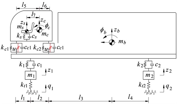
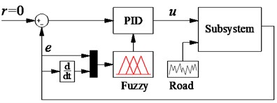
In this study, a heavy truck including the seat of the driver, cab, vehicle’s floor, and two front/rear wheel axles of the heavy truck is used. The suspension of the seat of the driver is used by the stiffness coefficient and damping coefficient ; the suspension of the cab is used by the stiffness coefficients and damping coefficients ; the suspension system of the vehile body are also used by the stiffness coefficients and damping coefficients ; and the wheels are characterized by the stiffness coefficients and damping coefficients , respectively. The dynamic model of the heavy truck is established in Fig. 1, where , , , and are the displacements of the seat, cab, vehicle body, and wheel axles inthe vertical derection; and are angular displacements of the cab and vehicle body; , , and are the mass of the seat of the driver, cab and vehicle; is the unsprung mass of the wheel axles; are the control forces of the cab’s suspension systems; is the excitation of the random road surface; are the vehicle’s distances ( 1-2; 1-7).
Fig. 1A dynamic model with the cab’s active suspension system of the heavy truck
Based on the heavy truck’s dynamic model, the motion equations of the driver’s seat, cab, and the vehicle body are given as follows:
The vibration equation of the driver’s seat:
where is the deformation of the driver's seat suspension determined as in Eq. (2):
The vibration equation of the cab:
where and are the front and rear deformations of the cab suspension determined as in Eq. (4); and are the front and rear active control of the cab suspension system:
The vibration equation of the vehicle body:
where the force responses of the cab suspension ( and ), force responses of the vehicle body suspension ( and ), and force responses of the wheels ( and ) are determined as in Eq. (6), respectively:
2.2. Vibration excitation of the road surface roughness
The roughness of the highway road surface greatly affects the interaction between the wheel and road surface and the road damage. It plays an important role in evaluating dynamic interaction between vehicles and roads. The random excitation of the road surface can be represented with a periodic modulated random process. The general form of the power spectrum density (PSD) of the road surface roughness is determined by [3, 16]:
where is the reciprocal space frequency of the wavelength; is the reference space frequency ( 0.1m-1); is the PSD of road surface under the reference space frequency known as the road surface roughness coefficient; and is the frequency index that decides the frequency configuration of PSD of road surface ( 2).
The road surface roughness is assumed to be a zero-mean stationary Gaussian random process. It can be generated through an inverse Fourier transformation:
where is the random phase uniformly distributed from 0 to 2.
According to the standard ISO 8068 [16], a type of road surface roughness of ISO level C is applied to evaluate the ride comfort of the heavy truck as well as the control methods of the semi-active cab suspension system. The simulation result of the typical road surface roughness of ISO level C is shown in Fig. 2.
Fig. 2The vibration excitation of the random road surface of ISO level C
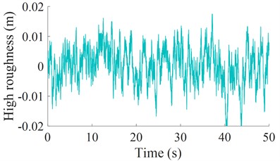
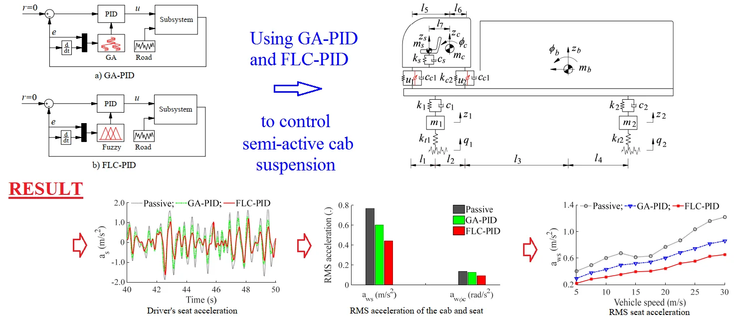
Fig. 3The control models of semi-active cab suspension.
a) GA-PID
b) FLC-PID
3. Semi-active cab suspension system with different control methods
Proportional-integral-derivate (PID) controller not only a simple structure but also robust performance. It is the most used in industrial process control. Its transfer function can be written as follows:
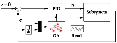
where , , and are the proportional, integral, and derivative parameters, respectively. The performance of the PID controller depends on the appropriate choice of the parameters of , , and . The well-known Ziegler-Nichols technique is used to choose these parameters. However, it is efficient only when the system works at the designed operating condition [3, 9]. To solve this problem, the GA and FLC combined with the PID are then applied to optimize the PID’s parameters for the semi-active suspension system of the heavy truck cab. The control models of the semi-active cab suspension system using the GA-PID and FLC-PID are shown in Figs. 3(a) and 3(b). Where and are the input parameters of the vehicle model while error (the relative displacement between the cab and vehicle body) and (its relative velocity) are the input parameters of the control models.
3.1. The GA-PID controller
The GA is applied to optimize the parameters of the vehicle suspension and engine [3, 17]. The researchers used the optimal suspension parameters of the vehicle, cab, and driver’s seat to reduce the RMS accelerations of the vehicle body, the cab, and the driver's seat. In this study, to use the GA for optimizing the PID's parameters, it is assumed that the operating parameters of the PID are from to }. Based on the vehicle dynamic model and cab suspension system, the GA’s program is simulated to choose the optimal parameters for the PID to reduce the RMS accelerations of the cab pitch angle and driver’s seat. The GA-PID controller is designed in Fig. 3(a). In which error and are two input values while three output values are the optimal of the GA for the PID controller to control the vehicle system model. The optimization condition of the GA is defined as follows:
where subscript denotes , , and , respectively; and are the RMS accelerations of the driver’s seat and cab pitching angle determined by [18]:
3.2. The FLC-PID controller
In section 3.1, the parameters of the PID controller are optimzed by the GA. However, under various operating conditions of the vehicle, the control forces are also changed. This means that the optimal parameters of the PID controller also need to be changed to optimize the control forces. Thus, the FLC is applied to control the parameters of the PID controller. The FLC-PID controller model is plotted in Fig. 3(b). Where error and are two input values of the FLC; three output values of the FLC are and these values are the input values of the PID controller. It is also assumed that the PID’s parameters are changed in a range from to . The PID's parameters in the FLC are changed in a range between 0 and 1 by the following linear transfer function [9]:
The design of the FLC is as follows: The cab’s suspension system deflection and its derivation are the two input values while the variable are three output values. The shape of the membership function for the variables of in-output is the Triangular function and their values are between 0 and 1. The nine linguistic terms are defined in Table 1 [12, 14].
The if-then rules in the FLC are applied to calculate the control forces according to expertise experiences and the designer’s knowledge. There are 49 control rules listed in Table 2 and if-then rules are described as follows:
(1) if nb and nb then pb;
(2) if nb and nm then pb;
(3) if pb and pb then nb.
The fuzzy inference system of Mamdani [12] which uses the minimum function and the centroid method has been mainly choisen to calculate the output values of the control force. Thus, the Mamdani's fuzzy inference in Matlab/Fuzzy is applied in this study.
Table 1Fuzzy linguistic values
Linguistic value | Description | Linguistic value | Description |
pb | Positive medium | ||
pm | Positive small | ns | Negative medium |
ps | Zero | nm | Negative big |
ze | Negative small | nb | Positive big |
Table 2Rule base for fuzzy control
nb | nm | ns | ze | ps | pm | pb | ||
nb | pb | pb | pb | pb | ps | ze | ze | |
nm | pb | pm | pm | ps | ps | ze | ze | |
ns | pb | pm | ps | ps | ze | ze | ns | |
ze | pb | ps | ps | ze | ns | ns | nb | |
ps | ps | ps | ze | ns | ns | nm | nb | |
pm | ze | ze | ns | ns | nm | nm | nb | |
pb | ze | ze | ns | nb | nb | nb | nb | |
Table 3The design parameters of the different heavy trucks
Parameter | Value | Parameter | Value |
(kg) | 120 | (Ns/m) | 7.029×10³ |
(kg) | 500 | (Ns/m) | 14.09×10³ |
(kg) | 19 000 | (N/m) | 1.38×10⁶ |
(kg) | 450 | (N/m) | 1.38×10⁶ |
(kg) | 1025 | (Ns/m) | 2.00×10³ |
(N/m) | 0.20×10⁵ | (Ns/m) | 2.00×10³ |
(Ns/m) | 0.20×10³ | (m) | 1.60 |
(N/m) | 1.00×10⁵ | (m) | 0.50 |
(N/m) | 1.00×10⁵ | (m) | 4.68 |
(Ns/m) | 0.75×10⁵ | (m) | 0.62 |
(Ns/m) | 0.75×10⁵ | (m) | 1.10 |
(N/m) | 1.02×10⁵ | (m) | 1.00 |
(N/m) | 5.45×10⁵ | (m) | 0.20 |
4. Results and analysis
To evaluate the control performance of the GA-PID and FLC-PID and the ride comfort of the vehicle, based on the vehicle’s dynamic parameters listed in Table 3, the semi-active cab suspension systems of the vehicle is controlled based on the GA-PID and FLC-PID.
4.1. Performance of the GA-PID and FLC-PID controllers
The GA-PID and FLC-PID controllers are applied to control the semi-active cab suspension system of the heavy truck under a random surface roughness of ISO level C at speed of 20 m/s. The simulation results are shown in Fig. 4. Fig. 4 shows that the acceleration responses of the driver’s seat and cabin pitch angle controlled by the GA-PID and FLC-PID are significantly decreased compared to the passive suspension of the heavy truck cab. Besides, the simulation results also show that the acceleration responses of the driver’s seat and cabin pitch angle controlled by the FLC-PID are smaller than that of the GA-PID. Especially, the calculation results of the RMS accelerations of the driver's seat and cab pitch angle in Fig. 5(a) with a semi-active cab suspension system using the FLC-PID are reduced by 26.45 % and 26.07 % in comparison with the GA-PID; and reduced by 48.16 % and 34.32 % in comparison with the passive cab suspension system. This means that the ride comfort with the FLC-PID is better than that of the GA-PID.
Fig. 4The acceleration responses of the cab and driver’s seat
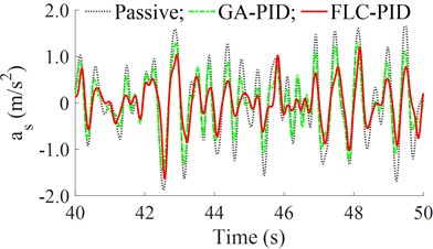
a) Driver's seat acceleration
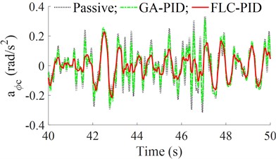
b) Cab pitch acceleration
Fig. 5The RMS values of the accelerations and control forces
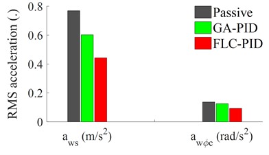
a) RMS acceleration of the cab and seat
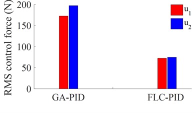
b) RMS control force of the cab suspension
Fig. 6The control forces of semi-active cab suspension
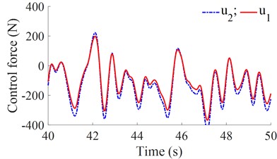
a) Control force of the GA-PID
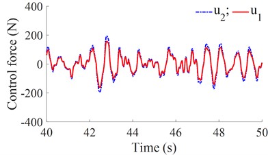
b) Control force of the FLC-PID
Additionally, the active control forces of the GA-PID and FLC-PID are also shown in Figs. 6(a) and 6(b). The results indicate that the maximum value of control forces generated by the GA-PID is an approximation of 420 N, while the maximum value of the control forces generated by the FLC-PID is an approximation of 250 N. Besides, the calculation results of the RMS values of the control forces with the GA-PID and FLC-PID in Fig. 5(b) indicate that the RMS control forces of the FLC-PID are smaller than that of the GA-PID. Especially, the RMS control forces of and with the FLC-PID are respectively reduced by 57.96 % and 62.02 % in comparison with the GA-PID. Thus, the FLC-PID not only better improves the ride comfort but also reduces the control forces and energy consumption.
4.2. Performance under the different velocities of the vehicle
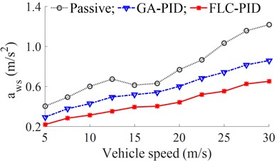
In this part, a range of the vehicle velocities from 5 km/h to 30 km/h are simulated to compare the performance of the semi-active cab suspension system of the heavy truck with the GA-PID and FLC-PID under the excitation of the random road surface of ISO level C. The simulation results of the RMS accelerations of the driver’s seat and cabin pitch angle are shown in 7(a) and 7(b). Besides, the comparison results of the RMS accelerations of the driver’s seat and cabin pitch angle between the GA-PID and FLC-PID are also listed in Table 4.
Fig. 7The RMS accelerations of the cab and driver’s seat
a) RMS seat acceleration
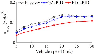
b) RMS acceleration of the cab pitching angle
Table 4The RMS acceleration of the driver’ seat and the cab pitch angle
Speeds (m/s) | (m/s2) | (rad/s2) | ||||
GA-PID | FLC-PID | Reduction (%) | GA-PID | FLC-PID | Reduction (%) | |
5 | 0.2942 | 0.2199 | 25.25 | 0.0470 | 0.0354 | 24.68 |
10 | 0.4286 | 0.3160 | 26.27 | 0.0789 | 0.0589 | 25.35 |
15 | 0.5185 | 0.3945 | 23.92 | 0.0973 | 0.0775 | 20.35 |
20 | 0.6020 | 0.4428 | 26.45 | 0.1258 | 0.0930 | 26.07 |
25 | 0.7425 | 0.5524 | 25.60 | 0.1277 | 0.1034 | 19.03 |
30 | 0.8598 | 0.6517 | 24.20 | 0.1274 | 0.1080 | 15.23 |
Figs. 7(a-b) and Table 4 show that in the speed range of the vehicle, the RMS accelerations of the driver's seat and cab pitch angle with a semi-active cab suspension system are significantly decreased in comparison with the passive cab suspension system. Besides, the results with the FLC-PID are also reduced compared to the GA-PID. Therefore, the ride comfort of the heavy truck with the FLC-PID is better improved compared to the GA-PID. Especially, at a range of the vehicle velocities from 20 m/s to 30 m/s, the RMS acceleration of the driver’s seat with the FLC-PID is greatly decreased in comparison with both GA-PID and without control; and the RMS accelerations of the driver’s seat and cab pitch angle with the FLC-PID at the vehicle speed of 20m/s are greatly reduced by 26.45 % and 26.07 % compared to the GA-PID. Thus, the driver’s ride comfort is strongly improved by the FLC-PID.
5. Conclusions
In this study, the combined control methods of the GA-PID and FLC-PID are researched and applied to control the semi-active suspension system of the heavy truck cab. The control results of the FLC-PID are better than that of the GA-PID in improving the ride comfort of the heavy truck under different operating conditions. Especially, when the vehicle moves at a velocity of 20 m/s, the RMS acceleration of the seat of the driver and cab pitching angle with the FLC-PID are greatly reduced by 26.45 % and 26.07 % in comparison with the GA-PID, respectively.
In addition, the control forces and energy consumptions used for the FLC-PID are also lower than that of the GA-PID. Therefore, the FLC-PID control should be applied to the suspension system of the vehicles to improve the vehicle’s ride comfort.
References
-
M. J. Mahmoodabadi, A. A. Safaie, A. Bagheri, and N. Nariman-Zadeh, “A novel combination of Particle Swarm Optimization and Genetic Algorithm for Pareto optimal design of a five-degree of freedom vehicle vibration model,” Applied Soft Computing, Vol. 13, No. 5, pp. 2577–2591, May 2013, https://doi.org/10.1016/j.asoc.2012.11.028
-
Nguyen van Liem, Zhang Jianrun, Le van Quynh, and Jiao Renqiang, “Study of fuzzy control for cab’s isolation system of heavy truck,” Vibroengineering Procedia, Vol. 10, pp. 309–314, 2016.
-
W. Wang, Y. Song, Y. Xue, H. Jin, J. Hou, and M. Zhao, “An optimal vibration control strategy for a vehicle’s active suspension based on improved cultural algorithm,” Applied Soft Computing, Vol. 28, pp. 167–174, Mar. 2015, https://doi.org/10.1016/j.asoc.2014.11.047
-
Y. Ye, V. Nguyen, and Y. Hu, “Vibration research of heavy trucks. Part 2: optimization of vehicle dynamic parameters,” Journal of Mechanical Engineering, Automation and Control Systems, Vol. 1, No. 2, pp. 124–133, Dec. 2020, https://doi.org/10.21595/jmeacs.2020.21814
-
H. Li, V. Nguyen, C. Wang, and Y. Xiu, “Vibration analysis and optimization of QZSS’s parameters added to vehicle’s seat suspension,” International Journal of Dynamics and Control, 2022, https://doi.org/10. 1007/s40435-022-01067-4
-
M. V. C. Rao and V. Prahlad, “A tunable fuzzy logic controller for vehicle-active suspension systems,” Fuzzy Sets and Systems, Vol. 85, No. 1, pp. 11–21, Jan. 1997, https://doi.org/10.1016/0165-0114(95)00369-x
-
P. Wang, N. Liem, and J. Zhang, “Experimental research and optimal control of vibration screed system (VSS) based on fuzzy control,” Journal of Vibroengineering, Vol. 22, No. 6, pp. 1415–1426, Sep. 2020, https://doi.org/10.21595/jve.2020.21560
-
S. Xu, J. Zhang, and L. Van, “Appling machine learning for car’s semi-activeair suspension under soft and rigid roads,” Journal of Southeast University, Vol. 38, pp. 300–308, 2022.
-
V. Nguyen, R. Jiao, and J. Zhang, “Control performance of damping and air spring of heavy truck air suspension system with optimal fuzzy control,” SAE International Journal of Vehicle Dynamics, Stability, and NVH, Vol. 4, No. 2, pp. 179–194, Feb. 2020, https://doi.org/10.4271/10-04-02-0013
-
L. C. Félix-Herrán, D. Mehdi, J. J. Rodríguez-Ortiz, R. Soto, and R. Ramírez-Mendoza, “H∞control of a suspension with a magnetorheological damper,” International Journal of Control, Vol. 85, No. 8, pp. 1026–1038, Aug. 2012, https://doi.org/10.1080/00207179.2012.674216
-
M. Ieluzzi, P. Turco, and M. Montiglio, “Development of an heavy truck semi-active suspension control,” IFAC Proceedings Volumes, Vol. 37, No. 22, pp. 547–552, Apr. 2004, https://doi.org/10.1016/s1474-6670(17)30400-7
-
K. Yi and J. K. Hedrick, “Active and semi-active heavy truck suspensions to reduce pavement damage,” SAE International Truck and Bus Meeting and Exposition, Vol. 43, No. 3, pp. 397–384, Nov. 1989, https://doi.org/10.4271/892486
-
G. Tsampardoukas, C. W. Stammers, and E. Guglielmino, “Hybrid balance control of a magnetorheological truck suspension,” Journal of Sound and Vibration, Vol. 317, No. 3-5, pp. 514–536, Nov. 2008, https://doi.org/10.1016/j.jsv.2008.03.040
-
Z. Xie, P. K. Wong, J. Zhao, T. Xu, K. I. Wong, and H. C. Wong, “A noise-insensitive semi-active air suspension for heavy-duty vehicles with an integrated fuzzy-wheelbase preview control,” Mathematical Problems in Engineering, Vol. 2013, pp. 1–12, 2013, https://doi.org/10.1155/2013/121953
-
Q. Guo, D. Zhao, X. Zhao, Z. Li, and X. Shi, “Active suspension control strategy of multi-axle emergency rescue vehicle based on inertial measurement unit,” Sensors, Vol. 21, No. 20, p. 6877, Oct. 2021, https://doi.org/10.3390/s21206877
-
“ISO 8068. Mechanical vibration-road surface profiles-reporting of measured data,” International Organization for Standardization, 1995.
-
S. Xu, V. Nguyen, X. Guo, and H. Yuan, “Lubrication efficiency of crankpin bearing using square-cylindrical textures of partial textures optimized by genetic algorithm,” Industrial Lubrication and Tribology, Vol. 73, No. 10, pp. 1248–1257, Dec. 2021, https://doi.org/10.1108/ilt-07-2021-0284
-
“ISO 2631-1: Mechanical vibration and shock-evaluation of human exposure to whole body vibration-Part 1: General Requirements,” International Organization for Standardization, 1997.
Cited by
About this article

This study is supported by the Key Scientific Research Project of Hubei Polytechnic University (No. 22xjz02A).
The datasets generated during and/or analyzed during the current study are available from the corresponding author on reasonable request.
The authors declare that they have no conflict of interest.
