Abstract
Energy efficiency is important for a greener future and economics. Looking at the energy usage statistics in Turkey, most of the energy is used by industry. In the study presented in this article, low-cost solutions for reducing throttling losses in hydraulic systems have been examined. In this context, two units using fixed displacement pumps were designed. The energy consumption of these hydraulic units during the working process has been measured and examined. In line with the measured values, both systems were compared in terms of energy efficiency. According to the results obtained, it has been observed that with the simple design changes that can be made in the hydraulic systems, there are 44.5 % throttling losses and 24.4 % energy efficiency in the total cycle time.
1. Introduction
Energy efficiency is an indispensable condition today. By increasing energy efficiency, costs can be reduced and a greener world can be left for the future. Today, as in every field, efficiency and energy saving have become very important phenomena in the field of production. Many studies are carried out to reduce the energy consumed for production in industrial facilities. High energy consumption greatly increases production costs as well as harms the environment. Considering that most of Turkey's energy needs are imported, energy efficiency becomes very important. According to the data for 2022, approximately 46 % of the annual electricity consumption of our country is used by the industry [1], [2]. This situation is one of the important problems in front of producing high volume products under increasing competition conditions. Therefore, it is important to review the energy consumption consumed by the machines in the production process and to reduce this consumption. Since hydraulic presses have large-scale usage in many areas [3, 4] of the industry, it is important to increase energy efficiency in these hydraulic systems. When the literature is searched, it seems possible to construct high efficiency, systematized, and high security systems in specially configured hydraulic systems [5], [6], [7].
The benefits of energy efficiency can be summarized as reducing production costs, providing a low carbon footprint and emission rates, and reducing the effects of climate change [8]. It is known that changing climates and experiencing extreme weather events adversely affect human health and the environment. Climate change, along with global warming, also affects the durability of structures and engineering materials [9]. Reducing energy consumption per unit product will reveal a more environmentally friendly approach.
Hydraulic systems are used extensively in excavators, presses, cranes, and loaders where performance, power, and torque are required such as iron, and steel, white goods and automotive [10], [11]. These systems are generally preferred where high carrying power is required for small equipment. Low wear, high service life, and overload protection are among the advantages of hydraulic systems. But there are also some disadvantages. These are pressure and flow losses, fluid leaks, compressibility, and the importance of fluids' viscosity under pressure [10]. Energy efficiency in hydraulic system design is an important issue that increases its importance day by day and needs attention. In this framework, the causes of energy losses in hydraulic systems can be listed as viscous friction of the fluid while passing through pipes and valves, and hydraulic internal leakages that occur during the operation of equipment such as pumps and valves [12]. At the same time, throttling valves used to provide the desired speed control in hydraulic systems also cause serious energy losses. Variable displacement pumps can be used in many systems to reduce throttling losses. However, variable displacement pumps are not preferred for simple applications due to their high cost. While producing hydraulic machines, fixed displacement pumps are used to provide cost-based and easier solutions.
With the revisions to be made to the machines, it is possible to minimize energy losses and thus save energy. When a literature review is made, the pump used in a hydraulic system works continuously despite the absence of an electric motor loading [1]. As can be understood from this example, it is seen that remarkable energy savings can be achieved with the studies to be carried out for the efficient use of machines. From the selection of the engine to the selection of the equipment used, research was made in many parts, and evaluations were made about energy efficiency.
The majority of researchers still focus on mechanical design and smart control solutions to save energy in pump unit Technologies [13]. Fixed displacement pumps are typically small, light, and inexpensive, and can be used in many designs [14]. In fixed displacement pump applications, there is a loss as the pump continues to rotate at a constant speed in the standby mode of the system [15], [16]. From this point of view, a design improvement in a rivet press in order to reduce throttling losses with a fixed displacement pump has been made within the scope of the presented study.
When we look at the literature on the flow control valve described in the article, it is seen that research is made on adjusting the sensitivity of in-line flow control valves. Moving elements such as the hydraulic motor, pump, control valve, and cylinder cause leakage and friction losses, resulting in a decrease in system efficiency [5]. Generally, fluid velocity in hydraulic systems is provided by a directional valve or throttle [5]. Studies have shown that throttling loss occurs during the movement of the valve core [5], [17]. The energy loss due to throttling is quite high compared to other losses in the hydraulic field and corresponds to 60 % of the total loss [5], [18]. When studies on reducing throttling losses and providing energy efficiency are examined, studies such as reducing the pressure loss caused by the throttle of the servo valve [19], design of a hydraulic servo system based on dual hydraulic accumulators to reduce the throttle loss and overflow loss of the system at the same time [20], use of green electro-mechanical actuators with high energy efficiency and control performance to control the hydraulic press movement [21] can be given as examples.
In the study presented in this article, low-cost solutions for reducing throttling losses in hydraulic systems were investigated. In this context, two units using fixed displacement pumps were designed. It is aimed to increase energy efficiency with a simple design change in hydraulic systems using fixed displacement pumps against increasing energy costs. In the hydraulic system where fixed displacement pumps are used, measurements were made with flow meters from two separate units as a standard and recommended application with high energy efficiency. With the measured values, the current drawn by the motor, flow rate, and pressure parameters were examined. The measured values and the two systems were compared in terms of energy efficiency. The results obtained from the measurement values and the current drawn by the motor consume 9 A in the idle movement of the cylinder in standard practice, while in the designed system with high energy efficiency, it consumes 5 A in the idle movement. The results obtained from the measurement values and the current drawn by the motor consume 9 A in the idle movement of the cylinder in standard practice, while in the designed system with high energy efficiency, it consumes 5 A in the idle movement. Thus, with the developed system, 24.4 % energy efficiency was achieved in 44.5 % cycle time in idle motion.
2. Methods
The hydraulic circuit diagrams of both systems examined in terms of energy efficiency by reducing throttling losses are shown in Fig. 1 and Fig. 2, respectively.
Fig. 1Standard hydraulic system diagram
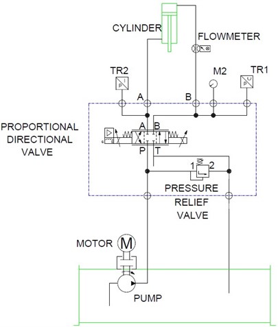
Fig. 2High energy efficient hydraulic system diagram
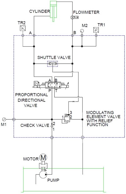
Fig. 1 shows the hydraulic circuit diagram of a system implemented in standard systems. The fixed displacement pump used starts to transmit oil from the tank to the system with the drive it receives from the engine. With the opening of the directional control valve, the oil flow is transmitted to the cylinder. While the roller is expected to move fast for idle movement, the speed is required to slow down in the crushing phase. After the cracking process is finished, the system should return quickly. For this reason, the directional control valve is used in proportional characteristics to provide cylinder speed adjustment. The safety valve, on the other hand, evacuates the oil back to the tank to prevent it from exceeding the pressure set in the system.
In Fig. 2, the pump starts to transmit the oil to the system with the drive it receives from the electric motor. Since it is not desired to exceed the oil pressure set in the hydraulic system, a pressure compensated safety valve is used for safety. After the proportional valve is opened, the oil flow that is throttled moves the cylinder forward or backward. In order for the pressure compensated safety valve to work synchronously with the proportional valve, it must receive a pilot warning from the cylinder lines. For this, a “Shuttle valve” has been added to the system.
The pressure compensated safety valve [22] both limits the maximum pressure of the system and tries to keep the pressure loss in the proportional valve used for throttling constant at 7 bar. In this way, it automatically adjusts itself according to the system’s need, not according to the maximum pressure set by the pilot warning received from the system during the movement of the cylinder at idle or at different loads. In this way, for example, the cylinder, which moves most of the stroke with 25 bar, must then increase to 120 bar crushing pressure. For this, the pressure compensated safety valve allows the pump to operate at approximately 32 bar first and then to 120 bar with increasing pressure requirement.
Transmitter (TR), and Manometer (M) abbreviations are used to express the operation of the process performed in Fig. 1 and Fig. 2.
In both hydraulic systems, the rivet press is set to take 3 seconds fast forward, and 2 seconds crushing, 2 seconds back take-off with specified times. There is also a 5 second idle time per cycle for new material to be loaded. When the calculation is made with the given times, the press makes a movement over 300 cycles per hour:
The Flow rate (L/min) in the system with the fixed displacement pump used in the system was calculated with Eq. (1). The desired Torque (Nm) is calculated using Eq. (2). In order to produce the calculated flow, how many Power (kW) should be used motor for the system is calculated with Eq. (3). Normally, the current that the selected electric motor will draw is certain. With a small change in the system, the current drop in the system can be detected.
3. Results and discussion
For both systems, measurements were made by connecting the test set to the data collection device. Fig. 3 and Fig. 4 show the flow, flow, and pressure values measured from hydraulic systems.
When the graph of the standard hydraulic system is examined in Fig. 3, while the cylinder moves at 25 bar, a flow rate of 11 liter/minute passes through the proportional valve. Meanwhile, the current drawn by the motor is approximately 9 A. When the system switched to crushing, the cylinder pressure increased to 120 Bar, and the current drawn by the engine was measured at approximately 11 A.
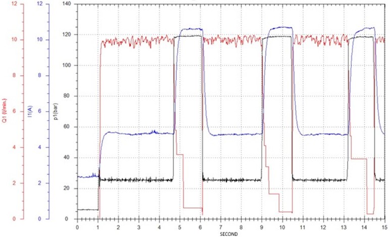
When the graph of the hydraulic system with high energy efficiency is examined in Fig. 4, the cylinder passes a flow rate of 10 liters/minute while moving at 25 bar. The current drawn by the motor is about 5 A. The current drawn by the motor at 120 bar when the roller starts to crush is 11 A. In addition, it should be emphasized here that; the formulas and calculations of these graphs are the same. As given in Fig. 3, the motor current is drawn 9 A in case of oil throttling. In Fig. 4, which shows the developed system, it is seen that in the case of oil throttling, it goes down to 5 A.
Considering these values, 44.5 % energy efficiency has been achieved due to throttling losses. 24.4 % energy efficiency has been achieved for the whole machine. Considering the calculated values, energy efficiency has been achieved with a very simple application. In addition, it has been a solution to systems with both energy efficiency and low cost.
Fig. 3Measurement of standard hydraulic system
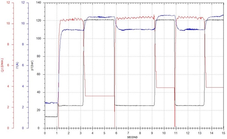
Fig. 4Measurement of high energy efficient hydraulic system
4. Conclusions
As a result, it has been seen that high energy efficiency can be achieved with a simple design change in the systems installed with the fixed displacement pump. When the results obtained are examined; In the case of oil throttling, while the motor current drawn is 9 A, it is clearly seen that this value decreases to 5 A in the developed system. According to these results, in standard and developed two different hydraulic applications, 44.5 % energy efficiency due to throttling losses and 24.4 % energy efficiency in the total machine movement was achieved.
At the same time, as a result of the energy efficiency obtained, the oil in the tank will heat up less and the need for cooling will decrease considerably. In this way, the need for the use of cooling equipment will be reduced and therefore a lower cost system will be designed.
References
-
“Electricity.” Republic of Turkey Ministry of Energy and Natural Resources. https://enerji.gov.tr/bilgi-merkezi-enerji-elektrik (accessed 2022).
-
Y. Sinir, “Estimation of Turkey industrial electricity consumption with artificial neural networks for the 2017-2023 period,” (in Turkish), Journal of Applied Sciences of Mehmet Akif Ersoy University, Vol. 3, No. 2, pp. 206–228, Sep. 2019.
-
Dzka-Dahlke, P. Deptuła, D. J. R., and Browski, “Usage of the powder metallurgy method for fabrication of titanium implant alloy,” Journal of Vibroengineering, Vol. 9, No. 3, pp. 100–105, 2007.
-
L. Guannan, Y. Dayu, L. Xin, Z. Xiaoqian, and G. Feng, “Study on microstructure mechanism of sandstone based on complex network theory,” Journal of Measurements in Engineering, Vol. 8, No. 1, pp. 27–33, Mar. 2020, https://doi.org/10.21595/jme.2020.21090
-
A. C. Mahato and S. K. Ghoshal, “Energy-saving strategies on power hydraulic system: An overview,” Proceedings of the Institution of Mechanical Engineers, Part I: Journal of Systems and Control Engineering, Vol. 235, No. 2, pp. 147–169, Feb. 2021, https://doi.org/10.1177/0959651820931627
-
T. C. Do, D. G. Nguyen, T. D. Dang, and K. K. Ahn, “A boom energy regeneration system of hybrid hydraulic excavator using energy conversion components,” Actuators, Vol. 10, No. 1, Dec. 2020, https://doi.org/10.3390/act10010001
-
D. Zhang, J. Gong, Y. Zhao, C. Liu, P. Hu, and Z. Tang, “Research on a new energy-recovery system for hybrid hydraulic excavators,” in IOP Conference Series: Earth and Environmental Science, Vol. 300, No. 4, p. 042003, Jul. 2019, https://doi.org/10.1088/1755-1315/300/4/042003
-
M. Naimoglu and M. Akal, “An overview on energy efficiency in view of supply and demand,” (in Turkish), Verimlilik Dergisi, Vol. 3, No. 3, pp. 3–20, Nov. 2020, https://doi.org/10.51551/verimlilik.698615
-
B. Valdez, M. Schorr, M. Quintero, R. García, and N. Rosas, “Effect of climate change on durability of engineering materials in hydraulic infrastructure: An overview,” Corrosion Engineering, Science and Technology, Vol. 45, No. 1, pp. 34–41, Feb. 2010, https://doi.org/10.1179/147842209x12559428167526
-
M. Vašina, L. Hružík, and A. Bureček, “Energy and dynamic properties of hydraulic systems,” Tehnicki Vjesnik-Technical Gazette, Vol. 25, No. Supplement 2, pp. 382–390, Sep. 2018, https://doi.org/10.17559/tv-20131209081056
-
Ö. Güceyü, “Position control of a hydraulics system with PID algorithm,” (in Turkish), Inonu University Graduate School of Natural and Applied Sciences Department of Mechanical Engineering, 2013.
-
H. S. Ergür, “Energy Efficiency in Hydraulic Systems,” (in Turkish), Uludağ University Journal of The Faculty of Engineering, Vol. 23, No. 2, pp. 241–254, May 2018, https://doi.org/10.17482/uumfd.321820
-
H. Yang, J. Wang, and H. Liu, “Energy-saving mechanism research on beam-pumping unit driven by hydraulics,” PLOS ONE, Vol. 16, No. 4, p. e0249244, Apr. 2021, https://doi.org/10.1371/journal.pone.0249244
-
M. A. Batdorff and J. H. Lumkes, “Virtually variable displacement hydraulic pump including compressability and switching losses,” in ASME 2006 International Mechanical Engineering Congress and Exposition, pp. 1–10, Jan. 2006, https://doi.org/10.1115/imece2006-14838
-
Q. Li, J. Yang, S. Huang, P. Liu, Y. Feng, and L. Wang, “No-load electromagnetic performance analysis of a mechanically modulated permanent magnet homopolar inductor machine,” IEEE Transactions on Transportation Electrification, Vol. 8, No. 1, pp. 1168–1181, Mar. 2022, https://doi.org/10.1109/tte.2021.3105422
-
J.-I. Itoh, T. Nagano, K. Tanaka, K. Orikawa, and N. Yamada, “Development of flywheel energy storage system with multiple parallel drives,” in 2014 IEEE Energy Conversion Congress and Exposition (ECCE), pp. 4568–4575, Sep. 2014, https://doi.org/10.1109/ecce.2014.6954026
-
M. Rannow, “Achieving efficient control of hydraulic systems using on/off valves,” 2016.
-
H. C. Tu, M. B. Rannow, J. D. van de Ven, M. Wang, P. Y. Li, and T. R. Chase, “High speed rotary pulse width modulated on/off valve,” in ASME 2007 International Mechanical Engineering Congress and Exposition, Vol. 4, pp. 89–102, Jan. 2007, https://doi.org/10.1115/imece2007-42559
-
Z. Cui, X. Rong, and Y. Li, “Design and control method of a hydraulic power unit for a wheel-legged robot,” Journal of Mechanical Science and Technology, Vol. 36, No. 4, pp. 2043–2052, Apr. 2022, https://doi.org/10.1007/s12206-022-0339-8
-
W. Wang, W. Du, C. Cheng, X. Lu, and W. Zou, “Output feedback control for energy-saving asymmetric hydraulic servo system based on desired compensation approach,” Applied Mathematical Modelling, Vol. 101, pp. 360–379, Jan. 2022, https://doi.org/10.1016/j.apm.2021.08.032
-
S. Qiao, Y. Hao, L. Quan, L. Ge, and L. Xia, “A novel electro-hydraulic compound driving system with potential energy regeneration capability for lifting device,” IEEE Access, Vol. 10, pp. 18248–18256, 2022, https://doi.org/10.1109/access.2022.3149515
-
T. Data, C. Options, and T. Features, “MODEL RVCB model code example: RVCBLWN,” 2020.
Cited by
About this article

This work was carried out by HIPAS Hydraulics and Pneumatics Co.-Design Center.
The datasets generated during and/or analyzed during the current study are available from the corresponding author on reasonable request.
The authors declare that they have no conflict of interest.
