Abstract
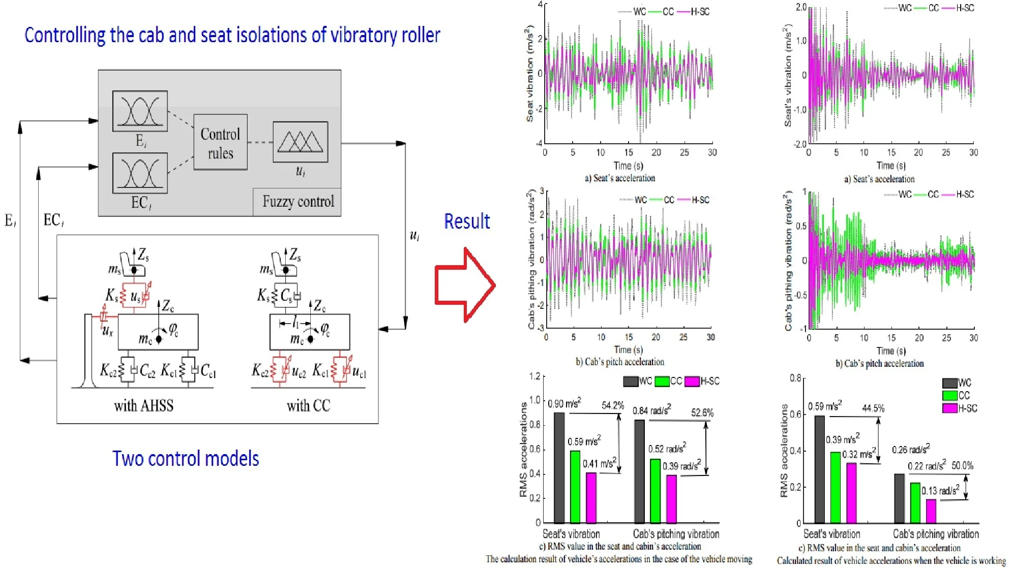
To reduce both the seat's vertical acceleration and cab pitching vibration in vibratory rollers, an active horizontal seat suspension (AHSS) is proposed and researched based on the dynamic model of the vibratory rollers moving and working and off-road grounds. The fuzzy control is applied to calculate the control force of the AHSS. The indexes in the Root Mean Square acceleration in the seat () and cab pitch angle () have been selected as the objective functions. The isolation performance of the HASS is then compared with the cab isolations controlled (CC) and without control (WC) under two conditions of the vibratory roller moving and working on the off-road surface. The study results show that the vibratory roller’s quality using the AHSS has been strongly ameliorated in comparison with both the CC and WC under both moving/working conditions. Especially, comparison with the WC, both the values of and with the AHSS are greatly reduced by 54.2 % and 52.6 % under the moving case and by 44.5 % and 50.0 % under working conditions of the vibratory roller. Therefore, the AHSS should be applied to improve both the seat's vertical comfort and shaking in vibratory rollers.
Highlights
- An active horizontal seat suspension (AHSS) is proposed and researched to reduce both the seat's vertical acceleration and cab pitching vibration in vibratory rollers.
- Both the values of RMSas and RMSap with the AHSS are greatly reduced by 54.2% and 52.6% under the moving case and by 44.5% and 50.0% under working conditions of the vibratory roller.
- The AHSS should be applied to improve both the seat's vertical comfort and shaking in vibratory rollers.
1. Introduction
The vibratory roller has been used to compact the off-road ground based on the interaction between the drum and off-road ground. To enhance the compression efficiency of the vibratory roller, the interaction models between the drum and off-road terrain have been studied to evaluate the interaction characteristics between the compaction force of the drum and the deformation of the off-road terrain [1-4]. Research results show that the density (stiffness) of the off-road terrain were gradually increased in the interaction process between the drum and the ground. This causes the vibrations of the drum and vibratory roller body to increase significantly. The existing research also showed that the seat vibration and pitch angle in the cab of vibratory rollers were strongly increased when vibratory rollers working and moving under deformed grounds and the drum's vibration excitations combined [3, 5, 6]. Therefore, cab isolations were always concerned and researched in recent years. Cab's traditional isolations using rubber isolators with their low isolating performance were replaced by using hydraulic isolation systems and controlled hydraulic isolation systems, pneumatic hydraulic isolation systems, and semi-active pneumatic hydraulic isolations to enhance the quality of vibratory rollers [7-10]. Thus, the ride comfort in vibratory rollers had been strongly decreased, especially with hydraulic isolation systems and controlled hydraulic isolation systems. But, with the standard of ISO-2631 [11], both seat vertical vibration and cab pitch vibration are still high. The quality of the driver is thus low, and it affects the driving performance of the driver in the working process.
In order to solve these issues, the control of fuzzy and control of the optimal fuzzy-PID had been used for controlling active dampers in the cab’s active hydraulic isolation systems [10, 12, 13]. Therefore, the cab shaking vibration and seat vertical vibration were better compared to the passive hydraulic isolation systems of the cab. However, its isolation performance was only reached under the operation case of vibratory rollers. The control of both cab shaking vibration and seat vertical vibration is difficult.
Therefore, to reduce both the cab's pitch vibration and the seat's vertical vibration, from the dynamic model of vibratory rollers, an auxiliary damper proposed and added in the horizontal direction in the cab, and an active suspension system of the seat controlled by a fuzzy controller are applied to the vibratory roller. Root Mean Square accelerations in the seat () and cab pitch angle () have been selected as objective indexes. The new point of this paper includes (1) the seat suspension system of the vibratory roller is controlled to improve the vertical comfort of the driver's seat and (2) a controlled auxiliary damper added in the horizontal direction of the vibratory roller cab to improve the cab shaking is proposed and researched.
2. Mathematical method
2.1. Vibratory roller’s dynamics model
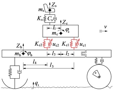
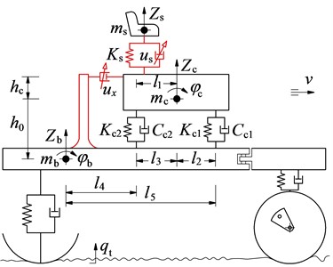
According to the structure of vibratory rollers shown in Fig. 1(a) [4, 14], the dynamics model of vibratory roller using its seven DOF has been established. Then, to reduce the cab’s pitching angle, a damper controlled by an active force () is added in the cab’s horizontal direction. Besides, the seat’s suspension controlled by an active force in the vertical direction is also used. The vehicle’s dynamic model added by the active horizontal seat suspension (AHSS) is plotted in Fig. 1(b). In addition, to evaluate AHSS performance, another method of vehicle’s dynamics model with the cab isolations controlled (CC) has been also applied to evaluate ride quality in vibratory rollers and compare the performance between AHSS and CC, the model of a vibratory roller with CC is given in Fig. 1(c).
Fig. 1Structure and dynamics of vibratory roller using two control methods
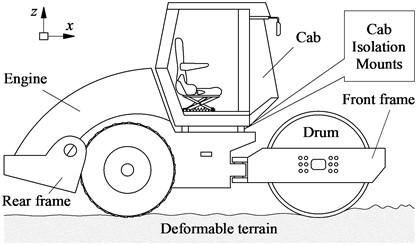
a) Single drum vibratory roller
b) The model of the vehicle with AHSS
c) The model of the vehicle with CC
Figs. 1(b-c), , , and are the seat mass, cab mass, and vehicle floor mass; , , and are vibrations of the seat, cab, and vehicle body; and are pitch angles of the cab and vehicle floor; and are stiffness/damping parameters in the seat's suspension; and are stiffness/damping parameters in cab isolations; is excitations of terrain; , , and are vehicle's distances; is the active force in the seat suspension system; is the active force of the cab's horizontal damper; and are the active forces in cab isolations, ( 1-5).
With the vehicle’s dynamics model given in Fig. 1(b), equations in the vehicle have been calculated as follows:
The force responses in the seat and cab isolations are determined by:
With the vehicle’s dynamics model given in Fig. 1(c), equations in the vehicle have been calculated as follows:
The force responses in the seat and cab isolations are determined by:
Dynamic forces in wheel/drum and deformed terrain interactions ( and ) are computed in the existing research of Refs. [4, 10, 15].
2.2. Excitation vibration sources
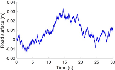
The case of vibratory rollers is working on off-road surfaces of the terrain, vibration excitations affect vibratory rollers including both drum vibration and off-road vibration [4, 16]. From excitation models of drum and terrain surface interactions in Ref. [16-18], the vibration excitation at the wheel and drum was computed and shown in Fig. 2. Then, this excitation has been used for assessing the comfort level of the vibrator roller with AHSS and CC, respectively.
Fig. 2Excitation of deformed terrain
3. Control method in cab and seat’s active suspensions
To control the active forces in AHSS and CC of the vibratory roller’s isolation systems for controlling the cab’s pitch angle as well as the seat’s vertical vibrations, the active forces of the and with the AHSS and the active forces of and with the CC are controlled by using the fuzzy control. Their control force equations are described as follows:
To control the active forces in Eq. (7), Fuzzy control has been used for controlling all the active damping forces in AHSS and CC following: (deflection) and (derivation) in the cab’s horizontal damper and seat's suspension with CC or AHSS are used as two variable inputs and a variable output is defined by the active damping forces of . The linguistic variables in and have been defined by Zero (Z), Positive small (Ps), Positive big (Pb), Negative big (Nb), and Negative small (Ns), whereas Linguistic variables in have been defined by Big (B), Medium big (Mb), Medium (M), Medium small (Ms), and Small (S). The values of Linguistic variables in two variable inputs ( and ) are operated from –1.0 to 1.0. These values are established based on the deformation and speed of the seat and cab isolations of the vibratory roller without control. The values of linguistic variables in variable outputs are operated from 0 to . The value of is also established based on the passive damping force of the seat and cab isolations of the vibratory roller without control. To build the if-then controls of Fuzzy control, based on the knowledge and experience of the designer, twenty-five control rules are provided in Table 1 and given as follows:
1) If = Nb and = Nb then = B,
2) If = Ns and =NZ then = B,
...
25) If = Pb and = then = B.
Then, Mamdani's centroid approach [19] is used to calculate the and control the active damping forces in AHSS and CC. The control block diagram for AHSS and CC has been given in Fig. 3.
4. Simulation results and analysis
To assess the isolation efficiency of AHSS and CC in improving ride quality as well as reducing the cab’s pitch angle, indexes of Root Mean Square accelerations in the seat () and cab's pitching angle () [20] are selected to analyze and compare the isolating efficiency between AHSS and CC. From the design parameters of the vibratory rollers with AHSS and CC in Table 2, the SIMULINK model established in MATLAB software has been applied for computing and controlling two models in vibratory rollers under two cases of moving/working on off-road terrain of vibratory rollers.
Fig. 3The control block diagram for AHSS and CC
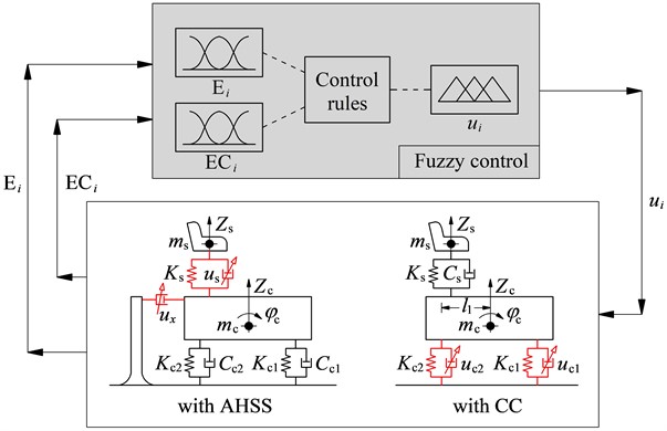
Table 1Control rules in the Fuzzy logic controller
Nb | Ns | Z | Ps | Pb | ||
Nb | B | Ns | M | Ms | Z | |
Ns | Nb | Nb | M | Z | Ms | |
Z | M | M | Z | M | M | |
Ps | Ms | Z | M | Mb | Mb | |
Pb | Z | Ms | M | Mb | B | |
Table 2Design parameters in the vibratory roller with AHSS and CC
Parameters | Values | Parameters | Values | Parameters | Values |
(kg) | 85.00 | , (m) | 0.100 | (m) | 0.136 |
(kg) | 891.0 | (m) | 0.383 | (m) | 0.760 |
(kg) | 4464 | (m) | 0.524 | (MNm) | 0.012 |
(m) | 0.400 | (Ns/m) | 20.00 | (MNm) | 0.910 |
(MN/m) | 0.120 | (kNs/m) | 4.500 | (kNs/m) | 0.120 |
4.1. Performance in the case of vehicle traveling
In the case of the vehicle moving to the roadwork, both the cab’s pitching vibration and the seat’s vertical vibration are greatly reduced under poor/very poor surfaces of off-road terrains [4, 16]. Therefore, the moving speed of the vibratory roller at = 10 km/h when the vehicle is moving on the poor surfaces of off-road terrain in Fig. 2 is used as the input singles for simulating and comparing the isolating efficiency between AHSS and CC via the control model in Fig. 3. The active damping forces of the AHSS and CC controlled by the fuzzy controller are shown in Fig. 4. Besides, the acceleration in the seat and cab's pitch angle has been also plotted in Fig. 5.
With the cab isolation system used by CC, both seat and cab accelerations are significantly decreased in compared to cab isolations without control (WC). Besides, with the cab and seat suspension used by AHSS, both the seat and cab accelerations are greatly reduced compared to both WC and CC, as indicated in Fig. 5(a) and Fig. 5(b). Especially, the compared result of and with the WC, AHSS, and CC in Fig. 5(c) shows that and with AHSS are greatly decreased by 54.2 % and 52.6 % in comparison with WC. The result is due to the seat suspension is directly controlled by to decrease the seat's vibrations while the cab’s pitch vibration is also directly controlled by the . Therefore, both vibrations of seat and cab are strongly reduced compared to both WC and CC. These results mean that the AHSS should be applied to seat and cab isolations in vibratory roller to improve both vertical comfort and shaking of both seat and cab.
Fig. 4Active damping forces in AHSS and CC
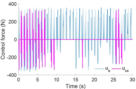
a) Active damping force in AHSS
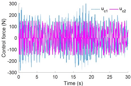
b) Active damping force in CC
4.2. Performance in the case of vehicle working
In the case of the vehicle working on the roadwork, both the cab’s pitch vibration and the seat’s vertical vibration are greatly reduced under the soil ground using the low-density at 28 Hz in the drum's excitation [3, 6, 15]. Thus, an excitation of the drum at 28 Hz when the vibratory roller is moving at a low speed of 3 km/h and compacting on the off-road terrain in Fig. 2 is used to simulate and compare isolating efficiency between AHSS and CC via the control model in Fig. 3. Simulated results in acceleration in both seat and cab have been plotted in Fig. 6.
Similarly, with the cab isolation system used by CC, both seat and cab accelerations are significantly decreased in compared to WC. With cab and seat suspension systems used by AHSS, both seat and cabin accelerations are greatly decreased compared to both WC and CC (see in Fig. 6(a) and Fig. 6(b). From the seat and cab accelerations simulated, both the results of the and with the WC, AHSS, and CC are calculated and compared in Fig. 6(c). Result shows that and with AHSS are also strongly reduced by 44.5 % and 50.0 % compared to WC. The result is also due to the seat suspension system being directly controlled by the to decrease the seat’s vibrations while the cab’s pitch vibration is also directly controlled by the . Based on the simulation and comparison results of WC, CC, and AHSS, we can see that AHSS used on the seat suspension system and cabin’s horizontal isolation strongly improves both driver comfort and cab shaking under different simulation cases in vibratory rollers. Thus, AHSS should be applied to improve the comfort and shaking of the vehicle.
Fig. 5The calculation result of vehicle’s accelerations in the case of the vehicle moving
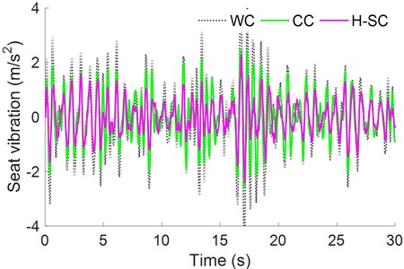
a) Seat’s acceleration
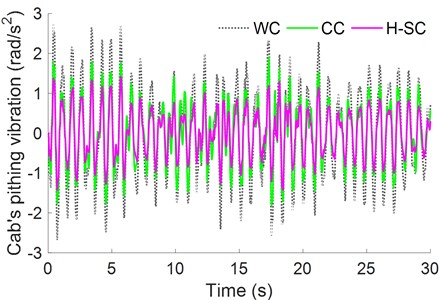
b) Cab’s pitch acceleration
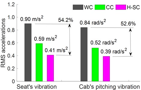
c) RMS value in the seat and cabin’s acceleration
5. Conclusions
An auxiliary damper with the active damping force and the seat's suspension controlled by the fuzzy controller are proposed, studied, and compared with both the WC and CC in improving both the comfort of the driver and the shaking of the cab in vibratory rollers.
Fig. 6Calculated result of vehicle accelerations when the vehicle is working
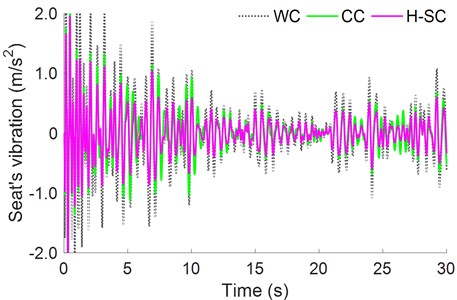
a) Seat’s acceleration
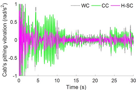
b) Cab’s pitch acceleration
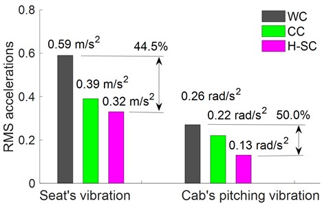
c) RMS value in the seat and cabin’s acceleration
Conclusions could be summarized via three steps:
1) In the case of vibratory rollers moving, both seat and cabin accelerations with AHSS are greatly decreased compared to both WC and CC, especially, both and with the AHSS are strongly reduced by 54.2 % and 52.6 % compared to WC.
2) In the case of vehicle working, both seat cabin accelerations with AHSS are greatly decreased compared to both WC and CC, especially, both and with AHSS are strongly reduced by 44.5 % and 50.0 % compared to WC. Thus, the AHSS used on the seat suspension system and the cab's horizontal isolation strongly improves both the comfort of the driver and the cab shaking under various simulation cases in vibratory roller.
3) The auxiliary damper with this active damping force has not been studied to improve the cab shaking. Based on this study result, the AHSS should be applied to improve both the vertical comfort and shaking of the vibratory rollers.
References
-
M. Bekker, Introduction to Terrain-Vehicle Systems. University of Michigan Press, 1969.
-
D. Adam and F. Kopf, “Teoretical analysis of dynamically loaded soils,” in Proceedings of the European Workshop Compaction of Soils and Granular Materials, pp. 207–220, 2000, https://doi.org/10.1007/978-3-319-40358-8_2.pdf
-
R. Anderegg and K. Kaufmann, “Intelligent compaction with vibratory rollers: feedback control systems in automatic compaction and compaction control,” Transportation Research Record: Journal of the Transportation Research Board, Vol. 1868, No. 1, pp. 124–134, Jan. 2004, https://doi.org/10.3141/1868-13
-
A. Kordestani, S. Rakheja, P. Marcotte Phd, A. Pazooki, and D. Juras, “Analysis of ride vibration environment of soil compactors,” SAE International Journal of Commercial Vehicles, Vol. 3, No. 1, pp. 259–272, Oct. 2010, https://doi.org/10.4271/2010-01-2022
-
C. Harnisch, B. Lach, R. Jakobs, M. Troulis, and O. Nehls, “A new tyre-soil interaction model for vehicle simulation on deformable ground,” Vehicle System Dynamics, Vol. 43, No. sup1, pp. 384–394, Jan. 2005, https://doi.org/10.1080/00423110500139981
-
V. Le, “Vibration study and control for cab of vibratory roller,” Ph.D. thesis, Southeast University, 2013.
-
T. Ushijima, K. Takano, and H. Kojima, “High performance hydraulic mount for improving vehicle noise and vibration,” in SAE International Congress and Exposition, Feb. 1988, https://doi.org/10.4271/880073
-
X. Sun and J. Zhang, “Performance of earth-moving machinery cab with hydraulic mounts in low frequency,” Journal of Vibration and Control, Vol. 20, No. 5, pp. 724–735, Nov. 2012, https://doi.org/10.1177/1077546312464260
-
V. Nguyen, J. Zhang, V. Le, and R. Jiao, “Vibration analysis and modeling of an off-road vibratory roller equipped with three different cab’s isolation mounts,” Shock and Vibration, Vol. 2018, pp. 1–17, Jan. 2018, https://doi.org/10.1155/2018/8527574
-
V. Nguyen, J. Zhang, and X. Yang, “Low-frequency performance analysis of semi-active cab’s hydraulic mounts of an off-road vibratory roller,” Shock and Vibration, Vol. 2019, pp. 1–15, Apr. 2019, https://doi.org/10.1155/2019/8725382
-
“Mechanical vibration and shock-evaluation of human exposure to whole body vibration-part 2: General requi,” ISO 2631-1:1997, International Organization for Standardization, 1997.
-
Y. Zhu, X. Bian, L. Su, C. Gu, Z. Wang, and C. Shi, “Ride comfort improvement with preview control semi-active suspension system based on supervised deep learning,” SAE International Journal of Vehicle Dynamics, Stability, and NVH, Vol. 5, No. 1, pp. 31–44, Jan. 2021, https://doi.org/10.4271/10-05-01-0003
-
V. Nguyen et al., “Ameliorating the vibratory roller’s ride quality based on QZSS and the seat’s semi-active suspension,” Journal of Southeast University, Vol. 39, pp. 89–97, 2023, https://doi.org/10.3969/j.issn.1003-7985.2023.01.011
-
D. Ni, R. Jiao, V. Nguyen, and J. Zhang, “Enhancing the ride comfort of off-road vibratory rollers with seat suspension using optimal quasi-zero stiffness,” Proceedings of the Institution of Mechanical Engineers, Part C: Journal of Mechanical Engineering Science, Vol. 237, No. 2, pp. 482–496, Aug. 2022, https://doi.org/10.1177/09544062221119929
-
J. Li, Z. Zhang, H. Xu, and Z. Feng, “Dynamic characteristics of the vibratory roller test-bed vibration isolation system: simulation and experiment,” Journal of Terramechanics, Vol. 56, pp. 139–156, Dec. 2014, https://doi.org/10.1016/j.jterra.2014.10.002
-
R. Jiao, V. Nguyen, and V. Le, “Ride comfort performance of hydro pneumatic isolation for soil compactors cab in low frequency region,” Journal of Vibroengineering, Vol. 22, No. 5, pp. 1174–1186, Aug. 2020, https://doi.org/10.21595/jve.2020.21345
-
V. Nguyen et al., “Ride quality evaluation of the soil compactor cab supplemented the auxiliary hydraulic mounts via simulation and experiment,” Journal of Southeast University, Vol. 35, pp. 273–280, 2019, https://doi.org/10.3969/j.issn.1003-7985.2019.03.001
-
J. Y. Wong, Theory of Ground Vehicles. NewYork: Wiley, 2001.
-
E. H. Mamdani, “Advances in the linguistic synthesis of fuzzy controllers,” International Journal of Man-Machine Studies, Vol. 8, No. 6, pp. 669–678, Nov. 1976, https://doi.org/10.1016/s0020-7373(76)80028-4
-
N. Nariman-Zadeh, M. Salehpour, A. Jamali, and E. Haghgoo, “Pareto optimization of a five-degree of freedom vehicle vibration model using a multi-objective uniform-diversity genetic algorithm (MUGA),” Engineering Applications of Artificial Intelligence, Vol. 23, No. 4, pp. 543–551, Jun. 2010, https://doi.org/10.1016/j.engappai.2009.08.008
About this article

This research is supported by the Key Scientific Research Project of Hubei Polytechnic University (No. 22xjz02A).
The datasets generated during and/or analyzed during the current study are available from the corresponding author on reasonable request.
Tianyuan Jiang has established the vibratory roller and simulates the results, Vanliem Nguyen has written all contents which have been presented in this paper, and Fan Zhang has plotted all figures in this paper.
The authors declare that they have no conflict of interest.
