Abstract
To have an overview of the research and development processes of the cab isolation system of the off-road vibratory rollers, this paper represents the researches of the various isolation systems based on the previously studied and published results. The result has shown that the ride comfort is mainly improved by the cab isolation system used the semi-active hydraulic mounts. The paper results can provide the overall view of the vibration studies of the off-road vibratory rollers.
Highlights
- Firstly, the traditional rubber and optimal rubber mounts are applied for cab isolation.
- Then, the hydraulic mount is researched for cab isolation.
- Finally, the semi-active hydraulic mount is successfully developed for the cab isolation system of the off-road vibratory roller.
- To study and control both the cab isolation system and the compaction force of the vibrator drum simultaneously not only improves the ride comfort but also enhances the compression performance.
1. Introduction
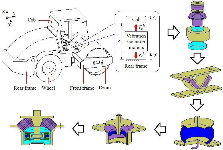
Since the production of the first commercial vibratory roller about 50 year ago, due to the trade competition, in recent years, the vibratory roller market had required not only increasingly working capacity but also enhancing the driver’s ride comfort. In order to reduce the effect of vibration on the operator, identification, and elimination of vibration sources generated in working conditions were the most important tasks for the designers. Therefore, the goal main of the designers is to enhance the vibratory drum’s force to reach maximum excitation result of the drum on the elasto-plastic [1-4], while reducing these vibration excitations transmitted to operator through the cab’s vibration isolation system and the seat’s suspension [5]. Therefore, the performance of the compression and the ride comfort of the vibratory rollers were strongly studied and improved in recent years [6-9].
In the vibration of the vibratory rollers, the excitation vibration sources yielded from the off-road terrains were mostly transmitted to the operator through cab and seat’s isolation systems [3, 10, 11]. Therefore, the vibration isolation system of the cab was one of the important indexes for isolating the vibration sources and improving the operator’s ride comfort [7, 8, 12, 13]. The research and improvement of the cab isolation system of the vibratory rollers to enhance the ride comfort were especially concerned [14]. The rubber mounts of the cab of the off-road vibratory rollers were investigated and optimized [6, 7]. Application of the hydraulic mounts [15] to reduce the cab’s pitch and roll angles of the off-road vehicles ware studied[8, 12]. The further development was the semi-active hydraulic mounts that were researched and applied for the cab isolation mounts of the off-road vibratory rollers [9, 14]. Based on the previously researched and published results of the ride comfort of the off-road vibratory rollers and the performance of the cab isolation system, this paper presents a summary of the research results of the isolation system of the vibratory roller cab and its structure in the improvement process.
2. Off-road vibratory rollers
2.1. Research of the vibration excitation sources
To study the ride comfort and reduce the vibration response of the vibratory roller cab, the vibration excitation sources of the vibratory roller were concerned and researched [1-3]. A two-degree-of-freedom (DOF) soil-compactor model was proposed to evaluate the compaction efficiently and determine the vibration response of the terrain on the drum [1, 16], as shown in Fig. 1.
Fig. 1Schematic of a vibratory roller [16]
![Schematic of a vibratory roller [16]](https://static-01.extrica.com/articles/21241/21241-img1.jpg)
a) Vibratory roller
![Schematic of a vibratory roller [16]](https://static-01.extrica.com/articles/21241/21241-img2.jpg)
b) Compaction model
Fig. 2Rigid drum-elastorplastic soil interaction model [6]
![Rigid drum-elastorplastic soil interaction model [6]](https://static-01.extrica.com/articles/21241/21241-img3.jpg)
a) Loading phase
![Rigid drum-elastorplastic soil interaction model [6]](https://static-01.extrica.com/articles/21241/21241-img4.jpg)
b) Unloading phase
Besides, the deformable soil properties in the compression process were also investigated through visco-elastic soil models of Pietzsch D. et al., and Anderegg R. et al. [17, 18]. The study results showed that during drum-soil interaction, the density and stress-strain properties of soil were altered after each pass of the vibratory drum. The soft deformation soil may exhibit elastic and elastic-plastic deformation during a given compaction pass. The elastic-plastic properties of the soil ground then observed during the loading and unloading phases of a compaction cycle. Therefore, Adam and Kopf established the rigid drum-elastoplastic soil ground interaction model to determine the vibration equations of the vibratory drum [6], as shown in Fig. 2.
Based on the rigid drum-elastorplastic interaction model [6, 16], the excitation force response of the vibrator drum is determined by:
where and are the elastic damping and plastic stiffness constants of the soil; and are the damping and plasticity factors of the soil; is the vertical projection of the rotating eccentric mass with its vibrator rotational velocity and eccentricity ; , in which is the excitation frequency of the vibratory drum.
The researched results [6] showed that the compression effect was achieved mainly at the low frequencies of 28-30 Hz or high frequencies of 34-35 Hz of the excitation drum. However, the excitation force response of the vibrator drum acting on the vehicle floor was also strongly affected in these frequency regions. Therefore, this rigid drum-elastoplastic soil interaction model which fully described the deformable characteristics of the terrain soil grounds in the compression process was almost used to determine the vibration excitation force of the drum into the vehicle body and cab floor to study the cab’s ride comfort, especially at the low and high excitation frequencies 28 Hz and 35 Hz of the viratory drum [7, 9].
Besides, the researches of the tire-soft soil interaction models proposed by Wong [19] had been applied for researching the effect of soil deformation on off-road vehicle ride responses [3, 10, 11, 13, 20]. Additionally, the influence of the tires-deformable interaction with the random terrain surface on the off-road vehicle’s ride comfort responses was also researched [8]. Six types of the tire-rigid terrain contact models including the point, roller, fixed footprint, radial spring, flexible ring, and finite element contacts were then carried out [13] to evaluate the vibration response of the tire-terrain contact, as shown in Fig. 3.
Fig. 3Tire-rigid terrain roughness contact models [13]
![Tire-rigid terrain roughness contact models [13]](https://static-01.extrica.com/articles/21241/21241-img5.jpg)
a) Point
![Tire-rigid terrain roughness contact models [13]](https://static-01.extrica.com/articles/21241/21241-img6.jpg)
b) Roller
![Tire-rigid terrain roughness contact models [13]](https://static-01.extrica.com/articles/21241/21241-img7.jpg)
c) Fixed footprint
![Tire-rigid terrain roughness contact models [13]](https://static-01.extrica.com/articles/21241/21241-img8.jpg)
d) Radial spring
![Tire-rigid terrain roughness contact models [13]](https://static-01.extrica.com/articles/21241/21241-img9.jpg)
e) Flexible ring
![Tire-rigid terrain roughness contact models [13]](https://static-01.extrica.com/articles/21241/21241-img10.jpg)
f) Finite element
Fig. 4Elastic tire-de formable terrain contact model [21]
![Elastic tire-de formable terrain contact model [21]](https://static-01.extrica.com/articles/21241/21241-img11.jpg)
For the contact point model, the tire is simplified into a parallel suspension structure where the upper end is connected to the vehicle axle and lower end is located at the contact point between the tire and road surface. This can convert the roughness of the road surface to vertical force as a vertical excitation of the vehicle. This model can be used to determine the vertical tire dynamic [42]. The disadvantage of this model is that it is difficult to determine the horizontal force of the tire to the change of the roughness of the road surface. In previous researches, the point contact of the tire-terrain contact model had almost used to study the vehicle’s ride comfort traveling because it was easy to determine the vertical dynamic force of the tire at the tire-deformable terrain contact [11, 12, 21]. In the study of vibration of the vibratory roller, the effect of the rough terrain surface to the vehicle’s ride comfort response was also almost concerned based on the point contact of the tires-terrain contact model [3, 4, 6-12]. To determine the vibration excitation of the tires-deformable terrain interaction, the point contact mode in Fig. 4 was used to describe the vibration excitation of tires.
Based on the elastic tire-deformable terrain contact model [21], the vibration excitation of the tires is determinded by:
Herein:
where and are the terrain stiffness coefficients for sinkage and internal friction, is the sinkage exponent, is the smaller dimension of the contact patch in which is the width of the tire, is the terrain cohesion coefficient, is the angle of the internal friction, in which is the slip ratio of the tire, is the shear deformation modulus; the sinking of the terrain is the sinking of the terrain.
Based on the modeling and force equation, the deformed soil such as soil, sand, rocks and gravel [19] affecting the ride comfort was studied in the publications of [10, 13].
Consequently, the influence of the off-road terrain and elastorplastic on the ride comfort of the soil compactors are mainly researched via the mathematical model of Eqs. (1) and (2).
2.2. Development of the cab isolation systems
2.2.1. Traditional rubber mounts for the cab
In order to isolate the vibration sources from the wheels and the vibratory drum to the operator of the off-road vibratory rollers, the cab and operator’s seat were almost equipped with the isolation systems of the traditional rubber mounts and seat’s suspension [6, 7, 22]. The structure of the vibratory roller cab used by the traditional rubber mounts was plotted in Fig. 5.
Fig. 5Traditional rubber mounts [22]
![Traditional rubber mounts [22]](https://static-01.extrica.com/articles/21241/21241-img12.jpg)
a) Single rubber mount
![Traditional rubber mounts [22]](https://static-01.extrica.com/articles/21241/21241-img13.jpg)
b) 3D rubber mount
Fig. 6Lumped model of the traditional rubber mount [7]
![Lumped model of the traditional rubber mount [7]](https://static-01.extrica.com/articles/21241/21241-img14.jpg)
The traditional rubber mounts (TRM) were mainly characterized by the high stiffness and low damping which was modeled by the lumped parameters as in Fig. 6, and its mathematical equation was written as follows:
where the visco-elastic properties of the TRM are mainly described by the linear damping and stiffness coefficient .
However, the research results showed that the vertical operator’s seat and cab shaking with the traditional rubber mounts were still great under operation conditions [6, 7, 22, 23], this problem is due to the influence of the low damping of the rubber mount. Consequently, the traditional rubber mounts were difficult to satisfy the operator’s ride comfort. Based on the analysis the characteristic and structure of rubber mount, the traditional rubber mount was then improved to enhance the rider comfort.
2.2.2. Improvement the rubber mounts for the cab
To improve the cab’s ride comfort of the vibratory rollers, the traditional rubber mount was then optimized by improvement its structure [7, 21], as shown in Fig. 7.
Fig. 7Optimal structure of the rubber mounts [21]
![Optimal structure of the rubber mounts [21]](https://static-01.extrica.com/articles/21241/21241-img15.jpg)
![Optimal structure of the rubber mounts [21]](https://static-01.extrica.com/articles/21241/21241-img16.jpg)
The parameters of and in the mathematical Eq. (4) was optimized. This optimal structure of the rubber mounts not only significantly improved the vibratory roller’s ride comfort but also reduced the cab shaking. Besides, based on the adaptive genetic algorithm and mutil-objective optimization method [24, 25], the lumped parameters of the rubber mounts was optimized to improve the vibratory roller ride comfort [9]. However, the vibration responses of the vibratory roller under the low-excitation frequency was very high, especially the pitching and rolling cab angles. This issue was due to the rubber mounts with the high stiffness and low damping characteristics which could only help to reduce the amplitude vibration and noise in the high-frequency range. Therefore, it is difficult to improve the vibratory roller’s ride comfort with cab isolation systems equipped with the traditional or optimal rubber mounts. In order to solve this problem, a new cab isolation system was proposed to improve the vibratory roller’s ride comfort in the low-frequency region [8, 12, 26-28].
Fig. 8Three types of cab isolation systems for the vibratory rollers [8]
![Three types of cab isolation systems for the vibratory rollers [8]](https://static-01.extrica.com/articles/21241/21241-img17.jpg)
a) Single drum vibratory roller
![Three types of cab isolation systems for the vibratory rollers [8]](https://static-01.extrica.com/articles/21241/21241-img18.jpg)
b) Rubber mount
![Three types of cab isolation systems for the vibratory rollers [8]](https://static-01.extrica.com/articles/21241/21241-img19.jpg)
c) Hydraulic mount
![Three types of cab isolation systems for the vibratory rollers [8]](https://static-01.extrica.com/articles/21241/21241-img20.jpg)
d) Pneumatic mount
2.2.3. Hydraulic mounts for the cab isolation system
Based on the model of the vibratory roller under the low excitation frequency below 10 Hz, the pitch and roll vibration response of the cab of three different isolation mounts including the traditional rubber mounts [21, 29], hydraulic mounts (HM) [12, 27, 30], and pneumatic mounts (PM) [15, 31-32], were compared and analyzed under various off-road terrains. The vibratory roller model with cab isolation systems was shown in Fig. 8.
Based on the dynamic model of the vibratory roller and cab isolation system, the lumped parameters of the cab isolation system with hydraulic mounts and pneumatic mounts were also modeled as in Fig. 9.
Fig. 9Lumped model of hydraulic and pneumatic mounts
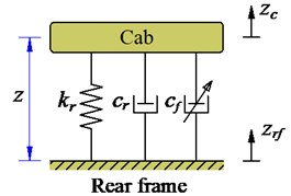
a) Hydraulic [12]
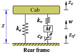
b) Pneumatic [31]
Theri mathematical equations of the vertical force responses of the HM and PM were described as follows:
where is the nonlinear damping parameter of the HPM in Fig. 9(a); , and are the static, viscous stiffness constants and mass of the air in the system, and is the nonlinear viscous damper of the air bag in Fig. 9(b).
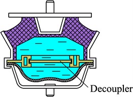
Three isolation mounts of TRM, HM and PM were then simulated and tested. The research results showed that the low-frequency and high-stiffness characteristics of the HM had a good effect on isolating low-frequency vibration transmitted and controlling the cab shaking of the off-road vibratory roller, and the characteristics of the PM also had the same results in comparison with the HM. This is due to the main peformance of the nonlinear liquid damping forces of the HM, and of the nonlinear viscous damping forces of the PM. Thus, the effect of the vibration on the driver’s ride comfort is significantly improved by both HM and PM in the low-frequency range below 10 Hz. However, the vibration and noise isolation performance of the HM is better than the PM in the frequency range up 10 Hz, this is due to the stiffness coefficient of the rubber visco-elastic property in the HM decided. Therefore, the HM has a very clear performance on the isolation vibration of the vibratory roller cab. Similarly, some researches of the cab’s hydraulic mounts for the vehicles moving on the off-road terrains also showed the good performance of the hydraulic mounts for isolation vibrations [12]. All research results clearly improved the ride comfort. However, the vibration of the vertical operator’s seat and pitching cab angle were still great under various operation conditions according to International Organization for Standardization, ISO 2631-1:1997 [33]. Based on the hydraulic mount used for engine isolation [29-30, 34] and its semi-active hydraulic mount with MR damper used for engine isolation [35-37], as shown in Fig. 10, the semi-active hydraulic mounts were then applied for the off-road vibratory roller cab to further improve the ride comfort in the low-frequency region.
Fig. 10Hydraulic mount for engine isolation systems
a) Passive [34]
b) Semi-active [35]
2.2.4. Semi-active hydraulic mount for the cab
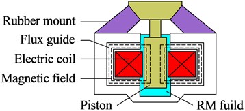
Based on the magnetorheological damper fluid which was used in almost semi-active suspension system [35, 38], a semi-active hydraulic mount using MR damper fluid for vibration isolation was then developed and applied for the cab isolation system to further improve the ride comfort performance in the low-frequency range of the vibratory rollers [9, 14]. The control model was built in Fig. 11.
Fig. 11Semi-active hydraulic mounts [9]
![Semi-active hydraulic mounts [9]](https://static-01.extrica.com/articles/21241/21241-img25.jpg)
a) Semi-active hydraulic mount
![Semi-active hydraulic mounts [9]](https://static-01.extrica.com/articles/21241/21241-img26.jpg)
b) Its lumped parameter model
The corresponding dynamic force of semi-active cab’s isolation mount in the vertical direction is given by:
where is the semi-active damping force of HM, and is an active damping force of MR fluid which is controlled by an optimal fuzzy-PID controller [9].
Based on the PID-Fuzzy control used the genetic algorithm program [26, 35, 38-40] to control the magnetorheological damper force of the semi-active hydraulic mount of , the simulation and experimental studies were given under both the vehicle conditions of the vehicle moving and compacting in the low frequency region and time region [9, 14, 41]. The study results showed that the semi-active hydraulic mount used on the vibratory roller cab significantly improved the operator’s ride comfort in comparison with the passive hydraulic mount or other cab isolation mounts such as the pneumatic or rubber mounts [9]. This is the optimal result of the cab isolation system for current soil compactors. The drivers ride comfort and cabin shaking angle have been greatly improved based on ISO 2631-1:1997 [33].
3. Conclusions
The research of the cab isolation system for the vibratory rollers to enhance the ride comfort has been constantly evolving in recent years. Firstly, the traditional rubber and optimal rubber mounts are applied for cab isolation, then, the hydraulic mount is researched for cab isolation. Finally, the semi-active hydraulic mount is successfully developed for the cab isolation system of the off-road vibratory roller.
Theoretical research results show that the semi-active hydraulic mount remarkably improves the operator’s ride comfort and controls the cab shaking under various working conditions of the vibratory rollers. However, the research results should be tested via the actual vibratory roller to apply for the cab of the off-road vibratory rollers.
Although the control technology has been studied and applied for the cab isolation system of the vibratory rollers, and its performance on reduction of the cab's vibrations is clear. However, the vertical vibration of the driver’s seat and cab shaking are still high according to ISO 2631-1:1997 [36], especially when the vibratory roller travels on the sandy terrain with low density. Therefore, to improve the ride comfort of the vibratory rollers in accordance with ISO 2631-1:1997, it is necessary to study and control both the cab isolation system and the compaction force of the vibrator drum simultaneously. This not only improves the vehicle’s ride comfort but also enhances the compression efficiency of the vibrator drum.
Based on the author’s understanding of the development the cab isolation system for the soil compactors as well as the outstanding issues that have not yet been thoroughly solved, especially the problem of the cab shaking. The author has two proposals for such solutions as follows: (1) Adding a horizontal damping mount to the cab can help reduce the horizontal impact force thus can prevent the cab shaking. (2) Based on the advantages of the resistance of both HM and PM, developing an hydro-pneumatic mount (HPM) and its control for the soil compactor cab is also needed.
References
-
Anderegg R., Kaufmann K. Intelligent compaction with vibratory rollers feedback control systems in automatic compaction and compaction control. Transportation Research Record, Vol. 1868, 2004, p. 124-134.
-
Harnisch C., Lach B., Jakobs R., et al. A new tyre-soil interaction model for vehicle simulation on deformable ground. Vehicle System Dynamics, Vol. 43, 2005, p. 384-394.
-
Irani R., Bauer R., Warkentin A. Dynamic wheel-soil model for lightweight mobile robots with smooth wheels. Journal of Intelligent and Robotic Systems, Vol. 71, Issue 2, 2013, p. 179-193.
-
Tateyama K., Ashida S., et al. Geomechatronics – Interaction between ground and construction machinery and its application to construction robotics. Journal of Terramechanics, Vol. 43, Issue 3, 2006, p. 341-353.
-
Kordestani A. Ride vibration and compaction dynamic of vibratory soil compactors. Concordia University, Montreal, Quebec, Canada, 2010.
-
Kordestani A., Rakheja S., et al. Analysis of ride vibration environment of soil compactors. SAE International Journal of Commercial Vehicles, Vol. 3, 2010, p. 259-272.
-
Le V. Vibration Study and Control for Cab of Vibratory Roller. Southeast University, 2013.
-
Nguyen V., Zhang J., et al. Vibration analysis and modeling of an off-road vibratory roller equipped with three different cab’s isolation mounts. Shock and Vibration, Vol. 2018, 2018, p. 8527574.
-
Van L., Zhang J., Yang X. Low-frequency performance analysis of semi-active cab’s hydraulic mounts of an off-road vibratory roller. Shock and Vibration, Vol. 2019, 2019, p. 8725382.
-
Park S., Popov A., Cole D. Influence of soil deformation on off-road heavy vehicle suspension vibration. Journal of Terramechanics, Vol. 41, Issue 1, 2004, p. 41-68.
-
Rinehart R., Mooney M. Instrumentation of a roller compactor to monitor vibration behavior during earthwork compaction. Automation in Construction, Vol. 17, Issue 2, 2008, p. 144-150.
-
Sun X., Zhang J. Performance of earth-moving machinery cab with hydraulic mounts in low frequency. Journal of Vibration and Control, Vol. 20, 2014, p. 724-735.
-
Zhang X. Modelling, Simulation and Optimization of Ride Comfort for of Road Articulated Dump Trucks. Southeast University, 2010.
-
Jiao R., et al. Improving ride comfort for vibratory roller utilizing semi-active hydraulic cab mounts with control optimization. Vibroengineering Procedia, Vol. 28, 2019, p. 75-80.
-
Hostens I., Deprez K., Ramon H. An improved design of air suspension for seats of mobile agricultural machines. Journal of Sound and Vibration, Vol. 276, Issues 1-2, 2004, p. 141-156.
-
Yoo S., Selig T. Dynamics of vibration roller compaction. Journal of the Geotechnical Engineering Division, Vol. 105, 1979, p. 1211-1231.
-
Pietzsch D., Poppy W. Simulation of soil compaction with vibratory rollers. Journal of Terramechanics, Vol. 29, 1992, p. 585-597.
-
Anderegg R., Wehrli C. Optimization of vibratory soil compactors and measurement of compaction. Eidgenössische Technische Hochschule, Zurich, 1995.
-
Wong J. Theory of Ground Vehicles. John Wiley and Sons, New York, USA, 2001.
-
Pakowski A., Cao D. Effect of soil deformability on off-road vehicle ride dynamics. SAE International Journal of Commercial Vehicles, Vol. 6, 2013, p. 362-367.
-
Jiao Q. Vibration simulation and optimization of the cab’s isolation system of the vibratory roller. Southeast University, 2010.
-
Adam D., Kopf F. Theoretical analysis of dynamically loaded soils. Proceedings of the European Workshop Compaction of Soils and Granular Materials, Paris, France, 2000, p. 207-217.
-
Li J., Zhang Z., et al. Dynamic characteristics of the vibratory roller test-bed vibration isolation system: simulation and experiment. Journal of Terramechanics, Vol. 56, 2014, p. 139-156.
-
Nariman Z., Salehpour M., et al. Pareto optimization of a five-degree of freedom vehicle vibration model using a MUGA. Engineering Applications of Artificial Intelligence, Vol. 23, Issue 4, 2010, p. 543-551.
-
John H., Michael G., Gregory D. Multi-objective control optimization for semi-active vehicle suspensions. Journal of Sound and Vibration, Vol. 330, 2011, p. 5502-5516.
-
Wang M., et al. A novel design of semi-active hydraulic mount with wide-band tunable notch frequency. Journal of Vibration and Control, Vol. 333, 2014, p. 2196-2211.
-
Lee P., Vogt J., Han S. Application of hydraulic body mounts to reduce the freeway hop shake of pickup truck. SAE Technical Paper 2009-01-2126, 2009, https://doi.org/10.4271/2009-01-2126.
-
Tikani R., Vahdati N., et al. A new hydraulic engine mount design without the peak frequency. Journal of Vibration and Control, Vol. 17, 2010, p. 1644-1656.
-
Hoang A., Le V. et al. Influence of damping coefficient into engine rubber mounting system on vehicle ride comfort. Vibroengineering Procedia, Vol. 29, 2019, p. 112-118.
-
Fan R., Lu Z. Fixed points on the nonlinear dynamic properties of hydraulic engine mounts and parameter identification method: Experiment and theory. Journal of Sound and Vibration, Vol. 305, 2007, p. 703-727.
-
M. Berg. A three-dimensional air spring model with friction and orifice damping. Proceedings of the 16th IAVSD Symposium, Vol. 33, 1999, p. 528-539.
-
Presthus M. Derivation of air spring model parameters for train simulation. Lulea University of Technology, 2002.
-
Mechanical Vibration and Shock-Evaluation of Human Exposure to Whole Body Vibration-Part 2: General Requirements. International Organization for Standardization, Tech. Rep. ISO 2631-1:1997, 1997.
-
Ushijima T., Takano K., Kojima H. High performance hydraulic mount for improving vehicle noise and vibration. SAE Paper, Vol. 97, 1988, p. 50-58.
-
Hong R., Choi B., et al. Non-dimensional analysis and design of a magnetorheological damper. Journal of Sound and Vibration, Vol. 288, 2005, p. 847-863.
-
Hong S., Choi S., et al. Non-dimensional analysis and design of a magnetorheological damper. Journal of Sound and Vibration, Vol. 288, Issue 2005, 2005, p. 847-863.
-
Baudendistel T., Tewani S., et al. Hybrid hydraulic mount with magnetorheological fluid chamber. U.S. Patent 6,412,761, 2002.
-
Félix-Herrán L., Mehdi D., et al. Hinfcontrol of a suspension with a magnetorheological damper. International Journal of Control, 2012, p. 1366-5820, https://doi.org/10.1080/00207179.2012.674216.
-
Rahmat M. Application of selftuning fuzzy PID controller on industrial hydraulic actuator using system identification approach. International Journal on Smart Sensing and Intelligent Systems, Vol. 2, Issue 2, 2009, p. 246-261.
-
Chen Y., Wang Z., Qiu J., Huang H. Hybrid fuzzy skyhook surface control using multi-objective microgenetic algorithm for semi-active vehicle suspension system ride comfort stability analysis. Journal of Dynamic Systems, Measurement, and Control, Vol. 134, Issue 4, 2012, p. 041003.
-
Nguyen V., Jiao R., et al. Performance of PID-Fuzzy control for cab isolation mounts of soil compactors. Journal of Mathematical Models in Engineering, Vol. 5, Issue 4, 2019, p. 137-145.
-
Captain M., Boghani B., Wormley N. Analytical tire models for dynamic vehicle simulation. Vehicle System Dynamics, Vol. 8, Issue 1, 1979, p. 1-32.
About this article

This study is supported by Hubei Polytechnic University Teaching and Research Projects [No. 19XJK17R].
