Abstract
The hydro pneumatic isolation (HPI) of the cab combined by the high static stiffness and nonlinear viscous damping of the pneumatic isolation; and nonlinear adjustable damping of the hydraulic isolation are proposed. Based on the simulation and experimental studies, a nonlinear dynamic model of the soil compactor interacting with the deformable terrains is built to analyze the low frequency ride comfort of the HPI. The HPI’s performance for improving the ride comfort and health of the driver is evaluated via both the power-spectral-density and root-mean-square of acceleration responses of the driver’s seat heave, pitching and rolling cab angles. The research results show that the HPI’s characteristics with high static stiffness and nonlinear damping have an obvious impact on reducing low frequency vibration and controlling the cab shake of the vehicle in comparison with the traditional rubber mounts.
Highlights
- The hydro pneumatic isolation (HPI) of the cab isolation are proposed and research on the ride comfort.
- A nonlinear dynamic model of the soil compactor interacting with the deformable terrains is built to analyze the low frequency ride comfort of the HPI.
- The TRI of the soil compactor is given and measured to determine the accuracy of the model.
- The research results: The HPI has an obvious impact on reducing low frequency vibration and controlling the cab shake.
- Moreover, the vibration isolation performance of the HPI can be further improved by optimizing or adopting active/passive control of the nonlinear damping coefficient.
1. Introduction
The soil compactor is a kind of equipment for road-building, and it belongs to the category of road equipment in construction machinery. It is widely used in filling and compaction of large engineering projects such as highway, railway, airport runway, dam, and stadium. With mechanical gravity and the excitation force of the drum, the soil compactor is suitable for compaction of sandy, semi-viscous and cohesive soil, subgrade stable soil and asphalt concrete pavement layer, so that the rolled layer will produce permanent deformation and compaction so that the compacted layer will produce permanent deformation and compaction [1, 2]. The current investigations on soil compactor show that the deformed terrain, especially the elastoplastic soil, has a great influence on the ride comfort of drivers [1, 3, 4]. Vibrations caused by the interaction between wheels and elastoplastic soil will be transmitted to the driver via the isolation systems of the seat and cab, as shown in Fig. 3(a). Besides, the vibration frequency is one of the important factors to calculate the design and determine the durability of mechanical structures. The well-know existing researches of Khalkar V. and Ramachandran S. had analyzed the effects of the natural frequencies of the spring steels [5-7], studied of free undamped and damped vibrations [8], and analyze the effects of the V-shape and the free vibration [9-11] of a cracked cantilever beam under all different experimental and simulated conditions. It was found that the vibration frequency was significantly affected by the spring stiffness of the structure and vice versa. In the vibration of moving mechanical devices, the vibration frequency should be determined through spring stiffnesses to reduce the effect of vibration on structural strength and travel stability. However, with the soil compactors roller moving and compacting on the deformed soil ground, the stiffness of the soil was changed and increased after the compaction process of the vibratory drum on the soil ground, thus, it is difficult to control the vibration stability of the vehicle. Also, the driver is very sensitive to low-frequency vibration, and the vibration generated by deformed terrain is often in the low frequency range of 0.5-10 Hz, which makes the driver feel extremely uncomfortable [12].
Therefore, the vibration isolation system of the cab is closely related to the physical and mental health of drivers and passengers, and its vibration isolation performance is one of the main factors to measure the ride comfort of vehicles. From the point of view of existing products, the traditional rubber isolation (TRI) with low damping and high stiffness is mostly used in the cab isolation system of the soil compactors [1-2, 4, 13, 14]. However, the rigidity of rubber is only good at absorbing high frequency vibration. Meanwhile, the low damping characteristic of rubber is not conducive to the control of low frequency vibration. Low frequency excitation will make the cab shaking, at this point, more damping is needed to consume the vibration energy [14].
In order to improve the vibration isolation performance of the TRI and enhance the ride comfort of the vehicle, Kordestani A. studied the influence characteristics of rubber vibration isolator parameters [1], and Nguyen V. L. optimized the TRI by adding auxiliary hydraulic suspension [2]. However, the results show that the cab shake is still serious under low frequency excitation. Therefore, the improvement of the ride comfort performance of the vehicle under low frequency vibration by TRI is limited.
The pneumatic isolation (PI) equipping the suspension systems of the cars, passenger vehicles, commercial vehicles, and high speed trains [15, 16] were also applied to cab isolation systems to improve the ride quality and health of the driver in the low frequency range [17, 18]. The researches indicated that both the nonlinear viscous damping and high static/elastic stiffness characteristics of the PI could control the vibration transmission and improve the driver’s ride quality. Furthermore, the PI not only appeared less resonant peaks but resonant peaks were lower than mechanical springs and TRI with equivalent properties [16]. Besides, the cab hydraulic isolation (HI) were also researched for the earth-moving machinery, construction equipment, and industrial vehicle to control the cab shaking as well as improve the ride quality [19, 20]. The results showed that the nonlinear liquid damping and high stiffness characteristics of the HI greatly reduced the acceleration responses of the cab in comparison with the TRI. However, according to the ISO 2631-1-1 evaluation standard, the vertical vibration of the driver’s seat and the pitch vibration of the cab are still large [21].
In order to make full use of the advantages of the PI and HI to improve the ride comfort and reduce energy consumption, a hybrid mathematical model of the hydro pneumatic suspension (HPS) was proposed and applied to agricultural tractors and dump trucks [22, 23]. They found that the ride comfort of the cab was greatly improved. Although the above research did not consider the influence of ground deformation, the results showed that the hybrid HPS could effectively improve vehicle ride comfort, which provided the direction and idea for the research in this study.
This paper, the hydro pneumatic isolation (HPI) combined by the high static stiffness and nonlinear viscous damping of the PI and the nonlinear adjustable damping of the HI are proposed for the soil compactor cab. A nonlinear dynamic model of the vehicle under the interaction of the wheels-elastoplastic soil at the frequency 35 Hz of the drum is built to analyze the HPI’s performance for improving the driver’s ride comfort and health. The HPI’s low frequency ride comfort is then evaluated via both the power-spectral-density (PSD) and root-mean-square (RMS) of acceleration responses of the driver’s seat heave, pitching and rolling cab angles in both the numerical simulation domains of the frequency and time.
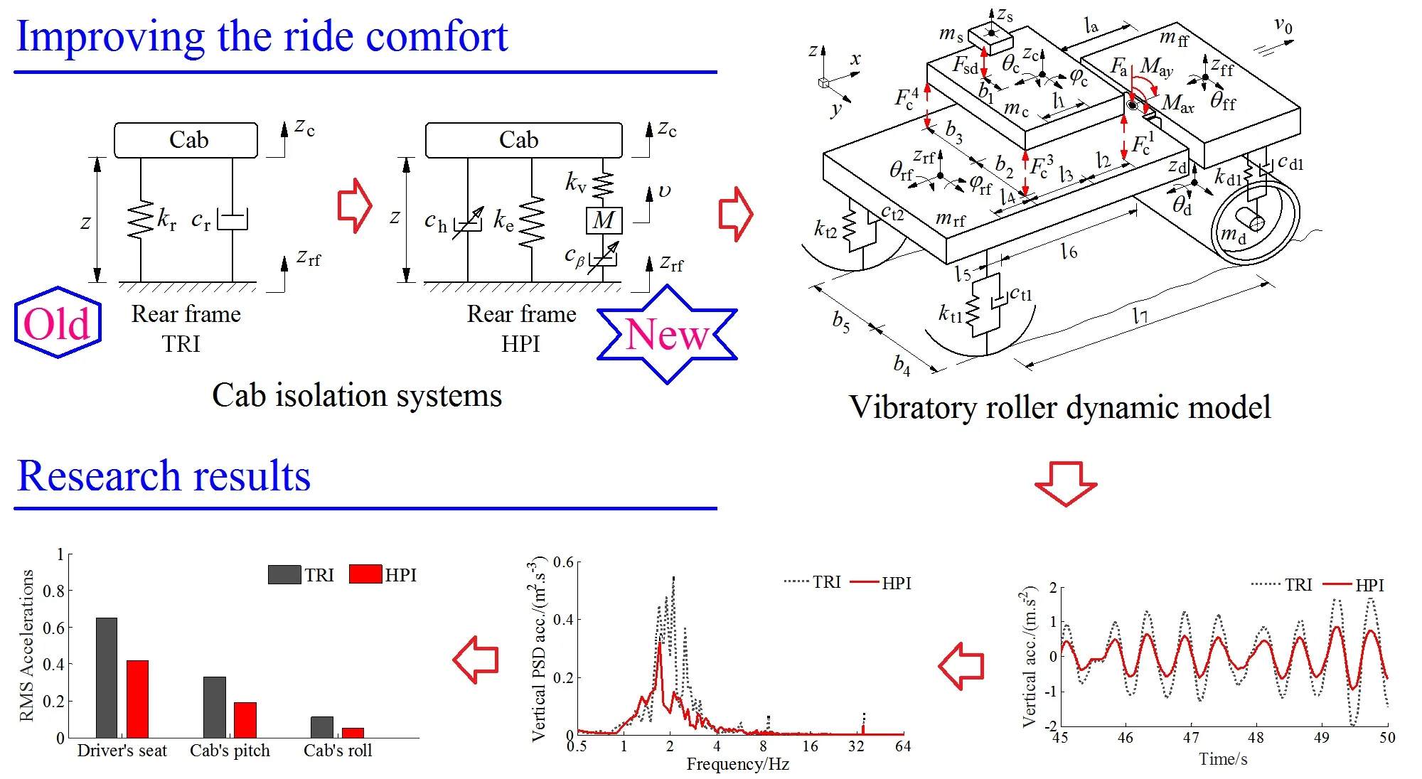
2. Hydro pneumatic isolation model
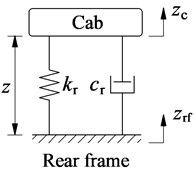
The cab of the soil compactor was mainly equipped with the TRI [1-2, 13] to isolate vibration sources transmitted from the vehicle frame to the cab floor, as given in Fig. 1(a). However, the isolation performance of these old rubber isolations was very low, especially the pitching vibration of the cab was very high [1, 3]. Thus, a new optimal design of the TRI was then carried out to improve the ride comfort [4], as illustrated in Fig. 1(b). Its mathematical model was shown in Fig. 2(a). The dynamic force of the TRI in the direction is given by:
where and are the linear damping and stiffness coefficients of the TRI, and are the nonlinear damping parameter of the fluid flow and nonlinear viscous damping parameter of the air in the air bag, , , and are the static, viscous stiffness constants and the mass of the air in the air bag, respectively.
Fig. 1Structure models of cab isolation systems
a) Old rubber isolation
b) New rubber isolation
c) Hydro pneumatic isolation
Fig. 2Mathematical models of cab isolation systems
a) TRI
b) HPI
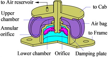
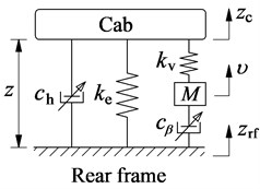
According to standard ISO 2631-1 [21], the isolation performance of these new rubber mounts was still low. Therefore, in this paper, a cab’s HPI for the soil compactors based on the isolation performance of both the HI [16] and PI [17] is proposed to further improve the ride comfort. The structure of the HPI mainly includes an air bag, damping plate, and closed chamber filled with the fluid, as plotted in Fig. 1(c). Its mathematical model is given in Fig. 2(b).
The nonlinear dynamic equations of the HPI is respectively calculated as follows.
1) With the dynamic force of air bag: The air bag’s dynamic responses are calculated based on the numerical values of the volume, temperature, mass, pressure, density, and shape of the air bag. Assuming that air bag is only deformed in the vertical direction . Thus, the new volumes of air bag and reservoir after deformation are:
where and is the air bag’s initial volume and effective area; is the reservoir’s initial volume; is the pipeline’s cross section area; and is the air’s displacement in surge pipe.
Based on the GENSYS model for calculating the dynamic parameters of the air bag [16], the static and viscous stiffness constants of and , and the mass of the air bag in Fig. 2(b) are given by:
where ; and are the initial pressure and polytropic rate of the air in the air bag; and are the length of the surge pipe and air density.
The corresponding static and viscous forces of and of the air bag in the vertical motion are given by [16]:
The nonlinear viscous damper is modeled in Fig. 2(b), which is only related to the velocity over the damping and determined by:
where the numerical values of , , , and are the loss coefficients due to friction, enlargement, contraction, and bends in the pipe, respectively.
The dynamic force of air bag in the vertical motion is then derived by:
2) With the dynamic force of hydraulic damper: Also assuming that the fluid inertial force in the orifices and the annular orifice is negligible, and fluid dynamic responses through the orifices and the annular orifice only move in the vertical motion . Therefore, the differential pressure of the upper and lower chambers was calculated as follows [14]:
where and are the parameters determined based on the geometric dimensions of the orifices and annular orifice; , , and are the influence of the chamber, orifices, and annular orifice areas; andis the relative velocity of the PHM.
The liquid damping force generated due to the differential pressure and the effect of the damping plate area on the fluid flow is calculated as follows:
where is the damping parameter of the HPI, as modeled in Fig. 2(b).
By combining Eqs. (6) and (8), the dynamic force of the HPI is written by the equation:
The HPI’s isolation performance is then simulated and compared with the TRI via Eq. (10) and vehicle model in section 3:
3. Modeling of the soil compactor
3.1. Model and motion equations of vehicle
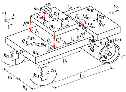
Based on the soil compactor’s actual structure in Fig. 3(a), a 3D nonlinear model with 11DOF of the vehicle dynamic is established to analyze the low frequency performance of the HPI, as modeled in Fig. 3(b).
Fig. 3Actual structure and nonlinear dynamic model of soil compactor
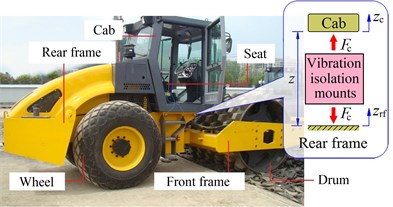
a) The actual structure of a vehicle
b) 3D dynamic model
In Fig. 3 the vertical motion of the driver’s seat is defined by ; the vertical, pitching, and rolling motions of the cab are defined by , , and , respectively, and those are also defined by , , and of the rear vehicle frame; the vertical and rolling motions of the drum and front frame are also defined by , and , ; the mass of the driver’s seat, cab, rear vehicle frame and engine, front vehicle frame, and drum are defined by , , , , and , respectively; the damping and stiffness parameters of the tires and drum’s rubber mounts are defined by , and , ; the longitudinal and transversal distances of the vehicle are defined by and ; is the distance from the articulated frame steered to the centre of gravity of front floor, ( 1-2, 1-6, 1-5).
Based on the nonlinear dynamic model of the soil compactor in Fig. 3(b), and by Newton’s second law of motion, the equations that describe the dynamic behavior of the vehicle can be written by the matrix form:
where is the mass matrix expressed as , then 0, and then is:
is the displacement vector with the 11DOF; is the vector of the forces and moments at centre of gravity of the seat, cab, front/rear frames, and drum in three motion directions of , , and .
According to the vertical motion of the seat, cab, front/read frames, and drum, the vector of vertical forces is respectively determined as follows:
The vertical dynamic forces and of the isolation mounts on the seat and cab floor are given by:
where and are damping and stiffness values of seat suspension; is the displacement of the cab floor at the seat; is the vertical dynamic force of the HPI or TRI to the cab floor at mount determined in Eq. (10).
The vertical dynamic forces , , and of the drum rubber mounts and tires on the front/rear frames and drum can be expressed by:
where and are the vibration excitation forces of the vibratory drum and tires determined via the models of the rigid drum-elastoplastic soil interaction and elastic tires-deformable terrain contact in Section 2.2.
Similarly, according to the pitching and rolling motions and of the cab, front/read frames, and drum, the vector of moments is also determined as follows:
The moments of the cab and rear frame in the pitching motion of can be expressed by:
The moments of the cab, rear/front frames, and drum in the rolling motion is described by:
where , and are the vertical force, the rotation moments of pitching and rolling axes at the articulated-frame steered.
3.2. Excitation forces of the drum and tires
The characteristics of elastic deformation and the elastodynamic response of the rigid soil ground surface to the movement of mechanical devices have been studied based on the model of the rigid disk embedded in a transversely isotropic full-space under forced harmonic excitations [24-26]. The vibrations of mechanical devices interacting with the soil ground are greatly affected by the elastoplastic soil with the rigid ground surface. In this study, based on the interaction model of the elastoplastic soil and rigid drum in Ref. [2], the excitation forces of the vibratory drum are written by:
where () and its derivative are determined by the equation of (; and are the elastic damping and plastic stiffness constants of the soil; is mass of the rotating eccentric of the drum; is the vertical projection of the rotating eccentric mass with its vibrator rotational velocity and eccentricity ; and are the damping and plasticity factors of the soil.
Besides, the excitation forces between the deformable terrain-elastic tire contact are given by Ref. [27]:
where and its derivative are determined by the equation of ; is the sinking of the soil under the wheel.
4. Experimental investigations
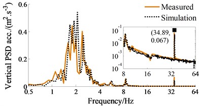
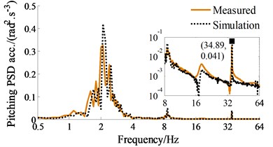
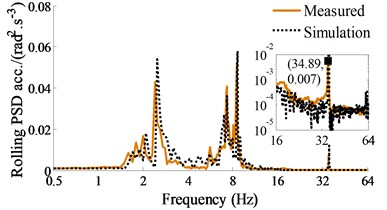
To assess the HPI’s performance via the soil compactor dynamic model, the TRI of the soil compactor is given and measured to determine the accuracy of the model. Based on the actual structure of the vehicle in Fig. 4(a) and its operation parameters listed in Table 1, both the numerical simulation and experimental processes are performed at a speed of 0.83 m·s-1 under the compaction condition of the vehicle on the elastoplastic soil at an excitation of the vibrator drum 35 Hz. The steps of the measurement process are made as follows: The ICP three-direction acceleration sensors, LMS dynamic test, and analysis system are applied to determine the accelerations on the seat and cab floor, as given in Fig. 4(a). Based on the signal processor and computer displaying the measured results, the measured datum of the accelerations of the driver’s seat heave, pitching and rolling cab angles are computed and displayed. The results of the PSD values of the driver’s seat heave, pitching and rolling cab angles are then compared with that of the simulation results, as depicted in Figs. 4(b)-(4d).
Fig. 4Experimental model and measured results of the soil compactor with TRI; 1, 3-Cab floor accelerometer, 2-Driver’ seat accelerometer, 4-Signal processor and display the results
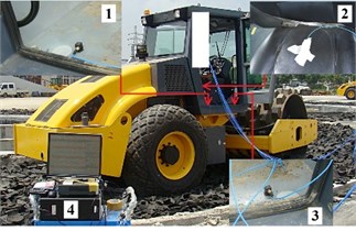
a) The experimental model of the soil compactor
b) Driver’s seat heave
c) Pitching cab angle
d) Rolling cab angle
The comparison results in Figs. 4(b)-4(d) indicate that the simulation results almost agree with the experimental results regarding the frequency of the various peaks in the responses and the trend, therefore, the mathematical model with the numerical values of the soil compactor is accurate and feasible. The vehicle dynamic model is then used to analyze the ride comfort performance of the HPI in the low frequency region.
5. Numerical simulations and discussions
5.1. Evaluation index and simulation conditions
Evaluation index: A good isolation system should have the ability to minimize vibration transmission to improve the driver’s ride comfort based on reducing the RMS acceleration response in the time region [2, 27]. Besides, the physical health and mental of the driver were influenced not only by the acceleration vibrations but also by the PSD acceleration response in the frequency region [14, 21]. According to the international standard ISO 2631-1 [21], the PSD value had been applied to assess the endurance limit of the human body under the impact of various vibration sources. The ISO 2631-1 showed that the driver’s health was seriously affected by the vertical vibration at a range of 4-10 Hz and rotational vibration of 0.5-2 Hz.
In this study, both the maximum PSD and RMS values of the driver’s seat heave, pitching and rolling cab angles are chosen as the indexes to evaluate the ride comfort performance of the HPI in comparison with the TRI. The results of the smaller PSD and RMS values of the corresponding isolation system mean its better performance. Their RMS values is given by:
where denotes the TRI or HPI; refers to the motional direction of the driver’s seat heave, pitching angle, or rolling cab angles; are the TRI or HPI accelerations in the , and is the simulation time.
Simulation conditions: To compare the isolation performance of the HPI with the TRI, the static stiffness of both the TRI and HPI is the same (), while the viscous stiffness and the mass of the air bag are calculated based on the air bag’s structure parameters. The low damping coefficient of the TRI depends on the nature damping of rubber, while the high nonlinear damping parameters are calculated based on the HPI’s structure parameters. The numerical values of the TRI and HPI listed in Table 1 are used for the simulation. Both the HPI and TRI are then simulated and compared under the same condition of the vehicle moving and compacting on the elastoplastic soil at a vibration excitation of the vibrator drum 35 Hz. Besides, the numerical values of a high density soil of the elastoplastic soil ground and an off-road terrain of Grenville loam with its poor surface roughness, as listed in Table 3, have been used as the excitation sources under the vibrator drum and wheels during the simulation. The vehicle model is then simulated and the evaluation index is used to analyze the HPI’s performance.
Table 1Numerical values of the soil compactor
Parameter | Value | Parameter | Value | Parameter | Value | Parameter | Value |
/ kg | 85 | / kgm2 | 1.2×10⁴ | / m | 0.383 | / N m-1 | 1.2×10⁴ |
/ kg | 891 | / kgm2 | 1.9×10³ | / m | 0.1 | / N m-1 | 3.9×10⁶ |
/ kg | 2822 | / kgm2 | 3.0×10³ | / m | 0.524 | / N m-1 | 0.5×10⁶ |
/ kg | 4464 | / m | 0.55 | / m | 0.136 | / Ns m-1 | 1.2×10² |
/ kg | 4378 | / m | 0.7 | / m | 0.76 | / Ns m-1 | 2.9×10³ |
/ kgm2 | 560 | / m | 0.68 | / m | 0.9 | ct1,2 / Ns m-1 | 4.0×10³ |
/ kgm2 | 523 | / m | 0.945 | / m | 0.6 | / Hz | 28/35 |
/ kgm2 | 3.1×10³ | / m | 0.945 | / m | 1.5 | / km h-1 | 3 |
Table 2Numerical values of the TRI and HPI
Isolation | Parameter | Value | Parameter | Value |
TRI | / Nm-1 | 9.1×10⁵ | / Nsm-1 | 218 |
/ Nm-1 | 1.2×10⁵ | / Nsm-1 | 29 | |
HPI | / kg | 98 | / kg | 33 |
/ Nm-1 | 9.1×10⁵ | / Ns2m-2 | 12.4×10³ | |
/ Nm-1 | 1.2×10⁵ | / Ns2m-2 | 10.7×10³ | |
/ Nm-1 | 15.3×10⁵ | / Ns2m-2 | 20×103 | |
/ Nm-1 | 2.01×10⁵ | / Ns2m-2 | 4.5×10³ |
Table 3Numerical values of the elastorplastic soil with its poor random surface
Parameter | Value | Parameter | Value | Parameter | Value |
/ N m-1 | 283×106 | , | 0.87, 1.01 | / Pa | 3.1×10³ |
/ N m-1 | 42.3×10⁶ | / N m-(n+1) | 0.06×10³ | 2.14 | |
/ Ns m-1 | 37.1×10³ | / N m-(n+2) | 5880×103 | / m3 cyc-1 | 3782.5×10-6 |
5.2. PSD acceleration results
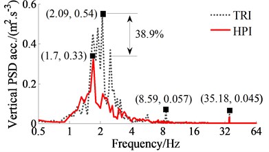
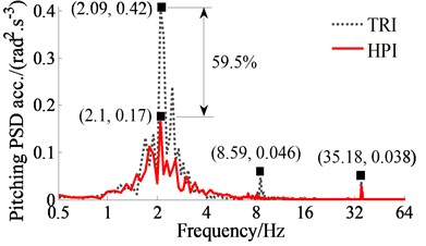
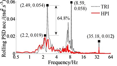
The comparison result of the PSD values with the HPI and TRI are plotted in Fig. 5, simultaneously, the comparison result of the resonance frequencies are also listed in Table 4. Observing the simulation results in Fig. 5 and Table 4, the PSD acceleration responses of the driver’s seat heave, pitching and rolling cab angles with the TRI appear more resonance peaks at the low frequency region, thus, the health of the driver is significantly affected by the elastoplastic soil ground with the high density soil. Contrary to TRI, the HPI’s resonance peaks appear less and their PSD values are lower, especially at 2.09 Hz, 2.49 Hz, and 8.59 Hz. Additionally, due to the influence of the elastic stiffness of air bag, the HPI’s resonance frequencies are significantly varied in comparison with that of the TRI.
Fig. 5Frequency responses of the driver’s seat and cab
a) Driver’s seat heave
b) Pitching cab angle
c) Rolling cab angle
At an excitation frequency range below 10 Hz, the resonance peaks of all PSD acceleration responses with the HPI are strongly reduced. Particularly at a low frequency range below 4 Hz, the maximum PSD values of the driver’s seat heave, pitching and rolling cab angles with the HPI are greatly decreased in comparison with the TRI by 38.9 %, 59.5 % and 64.8 %. This can be due to the effect of the nonlinear viscous damping forces and the nonlinear liquid damping forces of the hydraulic damper. In addition, due to the stiffness of the HPI is changed and depended on the volume and pressure of air bag in the operation process. Thus, the influence of the vibration on the driver’s health is significantly improved by the HPI in the low frequency range below 10 Hz.
At the excitation frequency range upper 10 Hz, the resonance frequencies of the PSD accelerations with the TRI also occur at 35.18 Hz under the frequency excitation of the drum in all three directions. This is due to the effect of the resonance at the excitation 35 Hz of the vibrator drum. Therefore, the HPI equipped for cab isolation mounts of the soil compactors can better improve the driver’s health in the low frequency range in comparison with the TRI.
Table 4Resonance frequencies of TRI and HPI
Mounts | Resonance frequency / Hz | ||||||
TRI | 1.69 | 1.89 | 2.09 | 2.49 | 5.69 | 8.59 | 35.18 |
HPI | 1.7 | 2.1 | 2.2 | 35.10 | |||
5.3. RMS acceleration results
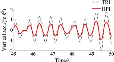
The PHI’s performance is evaluated not only by the driver’s health via the PSD values but also by the driver’s ride comfort via the RMS values. The acceleration responses of the driver’s seat and cab are also depicted in Fig. 6. Observing the simulation results, we can see that the acceleration results with the HPI are lower than that of the TRI under the elastoplastic soil ground and at the excitation 35 Hz of the vibrator drum.
Fig. 6Acceleration responses and RMS acceleration results of the driver’s seat and cab
a) Driver’s seat heave
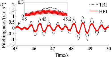
b) Pitching cab angle
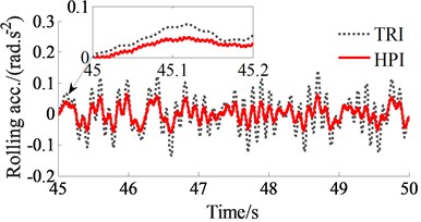
c) Rolling cab angle
To emphasize clearly the HPI’s performance, the RMS accelerations of the driver’s seat and cab are given in Fig. 7. The comparison results also show that the RMS values of the driver’s seat heave, pitching and rolling cab angles with the HPI are remarkably reduced in comparison with the TRI by 35.4 %, 42.4 %, and 52.7 %, respectively. This can also be due to the impact of both the nonlinear viscous damping force with its high nonlinear viscous damper and liquid damping force with its high nonlinear liquid damper . Therefore, it can be concluded that the driver’s ride comfort is remarkably improved by the HPI.
Fig. 7RMS results of the driver’s seat and cab at an excitation drum 35 Hz
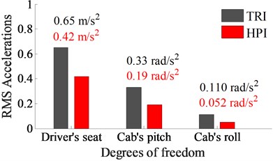
Table 5RMS acceleration results of the driver’s seat and cab with cab’s isolations of the soil compactor
Isolations | TRI | PI | HI | AHI | HPI |
/ m.s-2 | 0.65 | 0.63 | 0.51 | 0.58 | 0.42 |
/ rad.s-2 | 0.33 | 0.32 | 0.24 | 0.21 | 0.19 |
In addition, compared to the existing results of cab’s isolations for the vibratory rollers including the TRI [1], pneumatic isolation (PI) and hydraulic isolation (HI) [14], the TRI equipped with auxiliary hydraulic isolation (AHI) [2] under the same conditions of the simulation. The results of the driver’s seat heave and pitching cab angle are listed in Table 5. The comparison results show that the RMS acceleration responses of the driver’s seat and cab with the HPI are lower than all other isolations researched previously. Consequently, the HPI could provide the good ride comfort for the cab isolations of the soil compactors, particularly reducing the vibration of the driver’s seat heave and controlling the cab shacking.
6. Conclusions
Based on the measured and simulation results of the soil compactors, both the acceleration responses and PSD values with the HPI are greatly reduced in comparison with the TRI under the elastoplastic soil ground at the excitation 35Hz of the drum. Particularly, the maximum PSD values of the driver’s seat heave, pitching and rolling cab angles are strongly decreased by 38.9 %, 59.5 %, and 64.8 %, respectively; and their RMS values are also lower by 35.4 %, 42.4 %, and 52.7 %, respectively. Consequently, the cab’s ride comfort is remarkably improved by using the HPI.
Due to the vibration characteristics of the HPI with its high static stiffness and nonlinear damping, the HPI can effectively isolate the vibration transmission and control cab shake for the soil compactors in the low frequency region. Moreover, the vibration isolation performance of the HPI can be further improved by optimizing or adopting active/passive control of the nonlinear damping coefficient , which will provide a new idea for the low frequency vibration control of off-road vehicles.
References
-
Kordestani A., Rakheja S., et al. Analysis of ride vibration environment of soil compactors. SAE International Journal of Commercial Vehicles, Vol. 3, 2010, p. 259-272.
-
Nguyen V. L., Zhang J. R., et al. Ride quality evaluation of the soil compactor cab supplemented by auxiliary hydraulic mounts via simulation and experiment. Journal of Southeast University (English Edition), Vol. 35, Issue 3, 2019, p. 273-280.
-
Adam D., Kopf F. Theoretical analysis of dynamically loaded soils. Proceeding of European Workshop Compaction of Soils and Granular Materials, Paris, France, 2000, p. 207-220.
-
Jiao G. Vibration Simulation and Optimization of Cab’s Vibration Isolation System of Soil Compactor. Southeast University, 2010.
-
Khalkar V., Ramachandran S. The effect of crack geometry on stiffness of spring steel cantilever beam. Journal of Low Frequency Noise Vibration and Active Control, Vol. 37, Issue 4, 2018, p. 762-774.
-
Khalkar V., Ramachandran S. Vibration analysis of a cantilever beam for oblique cracks. Asian research publishing network. Journal of Engineering and Applied Sciences, Vol. 12, Issue 4, 2017, p. 1144-1150.
-
Khalkar V., Ramachandran S. Paradigm for natural frequency of an un-cracked cantilever beam and its application to cracked beam. ARPN Journal of Engineering and Applied Sciences, Vol. 12, Issue 6, 2017, p. 1714-1729.
-
Khalkar V., Ramachandran S. Study of free undamped and damped vibrations of a cracked cantilever beam. Journal of Engineering Science and Technology, Vol. 13, Issue 2, 2018, p. 449-462.
-
Khalkar V., Ramachandran S. The effect of crack geometry on non-destructive fault detection of EN 8 and EN 47 cracked cantilever beam. Journal of Noise and Vibration Worldwide, Vol. 50, Issue 3, 2019, p. 92-100.
-
Khalkar V., Ramachandran S. Analysis of the effect of V-shape and Rectangular shape cracks on the natural frequencies of a spring steel cantilever beam. Materials Today. Proceedings, Vol. 5, 2018, p. 855-862.
-
Khalkar V., Logesh K. The effect of crack geometry on mode shapes of a cracked cantilever beam. Australian Journal of Mechanical Engineering, 2020, https://doi.org/10.1080/14484846.2020. 1766349
-
Temmerman J., Deprez K., et al. Conceptual cab suspension system for a self-propelled agricultural machine-part 2: operator comfort optimization. Biosystems Engineering, Vol. 90, 2005, p. 271-278.
-
Li J. Q., Zhang Z. F., Xu H. G., Feng Z. X. Dynamic characteristics of the soil compactor test-bed vibration isolation system: Simulation and experiment. Journal of Terramechanics, Vol. 56, 2014, p. 139-156.
-
Liem N. V., Zhang J. R., et al. Vibration analysis and modeling of an off-road vibratory roller equipped with three different cab’s isolation mounts. Shock and Vibration, Vol. 2018, 2018, p. 1-17.
-
Sundvall P. Comparisons between predicted and measured ride comfort in trains-a case study on modeling. TRITAFKT Report, Division of Railway Technology, Department of Vehicle Engineering, Royal Institute of Technology, Stockholm, Sweden, 2001.
-
Presthus M. Derivation of Air Spring Model Parameters for Train Simulation. M.S. Thesis, Lulea University of Technology, 2002.
-
Yan J., Yin Z., Guo X., Fu C. Fuzzy control of semi-active air suspension for cab based on genetic algorithms. SAE Technical Paper, 2008, 2008-01-2681.
-
Tang G., Zhang H., Zhang Y., Sun Y. Studies of air spring mathematical model and its performance in cab suspension system of commercial vehicle. SAE Technical Paper, Vol. 2015, 2015, p. 341-348.
-
Lee P., Vogt J., Han S. Application of hydraulic body mounts to reduce the freeway hop shake of pickup truck. SAE Technical Paper Series, 2009, 2009-01-2126.
-
Jiao S. J., Wang Y., Zhang L., Hua H. Shock wave characteristics of a hydraulic damper for shock test machine. Mechanical Systems and Signal Processing, Vol. 24, 2010, p. 1570-1578.
-
Mechanical Vibration and Shock-Evaluation of Human Exposure to Whole Body Vibration-Part 2: General Requirements. International Organization for Standardization, ISO 2631-1:1997, 1997.
-
Sim K. Y., Lee H. Y., et al. Effectiveness evaluation of hydro-pneumatic and semi-active cab suspension for the improvement of ride comfort of agricultural tractors. Journal of Terramechanics, Vol. 69, 2017, p. 23-32.
-
Danish A., Samuel F. Artificial intelligence models for predicting the performance of hydropneumatic suspension struts in large capacity dump trucks. International Journal of Industrial Ergonomics, Vol. 67, 2018, p. 283-295.
-
Ahmadi S. F., Eskandari M. Vibration analysis of a rigid circular disk embedded in a transversely isotropic solid. Journal of Engineering Mechanics, Vol. 140, Issue 7, 2014, p. 04014048.
-
Eskandari M., Samea P., Ahmadi S. F. Axisymmetric time-harmonic response of a surface-stiffened transversely isotropic half-space. Meccanica, Vol. 52, Issues 1-2, 2017, p. 183-196.
-
Eskandari M., Ahmadi S. F., Khazaeli S. Dynamic analysis of a rigid circular foundation on a transversely isotropic half-space under a buried inclined time-harmonic load. Soil Dynamics and Earthquake Engineering, Vol. 63, 2014, p. 184-192.
-
Nguyen V., Run Z. J., et al. Effect of the off-road terrains on the ride comfor of construction vehicles. Journal of Southeast University (English Edition), Vol. 35, Issue 2, 2019, p. 191-197.
Cited by
About this article

This work has been supported by the National Key Research and Development Plan (No. 2019YFB2006402); Hubei Polytechnic University Teaching and Research Projects (No. 19XJK17R, 17XJZ03R); and Thai Nguyen University of Technology, TNUT, Viet Nam.
