Abstract
The spline pair needs to transmit large alternating torque and other directional loads, which causes the fretting wear of the spline pair to be serious, which leads to the failure of the spline pair connection and reduces the reliability of the entire transmission system. Therefore, it is of great significance to carry out research on fretting wear of spline pairs and improve the ability of splines to resist fretting wear. In this paper, based on the finite element method, a model considering the tooth fretting wear property of the agricultural tractor spline couplings model was developed to analyze changes of contact stress and relative slip distributions, in which the axis deviation was considered. The results show that axis deviation significantly increases the value of contact stress and relative slip in the spline couplings. With the increasing deviation, the value of contact stress and relative slip slightly raise accordingly. The friction coefficient shall not be too small when the system is lubricated. As a result, maintenance of the agricultural tractor transmission system can be required.
Highlights
- The axis deviation significantly increases the value of contact stress
- The axis deviation significantly increases the value of relative slip
- The friction coefficient shall not be too small when the system is lubricated
1. Introduction
The involute spline pair consists of internal and external splines. Compared with other key couplings, spline pairs have the characteristics of automatic centering, good tooth surface contact, long life, and large bearing capacity. They are widely used in agricultural products, especially in high-power tractor drive systems. Therefore, scholars have carried out a lot of research on involute spline pairs.
Francesca C. [1-4] carried out an experimental and numerical research on fatigue damage, and the results show that the actual part life was higher than that calculated by the standard method. Waqar Q. [5-6] used a special test bench to test the spline coupling made of 42CrMo4, and found that clearance and fretting wear are directly related to torque and eccentricity. Hong J. [7] established a global contact analysis model to quantify the effect of indexing errors of the manufactured teeth on the spline load distribution. Nguyen-Thanh N. [8] studied the RHT method to locally refine the spline model calculations. Yi G. [9] verified that when the torque is greater than the threshold, the spline motion amplitude is greatly reduced. Xiang Z. X. [10] analyzed the wear mechanism and accurately predicted spline fretting wear by an improved method.
Han B. H. [11] used Gear and gave a feasible method for accurate 3D solid modeling of spline parts. Li Y. Z. [12] analyzed the production process of spline shaft parts, including cutting and plastic forming, and reached some progress of production process of spline shaft parts. Zhao H. M. [13, 14] studied a method of alternating current motor and raise aSemi-supervised broad learning system. Chen Y. Y. [15] established a finite element model to study the influence of the relative length of the sizing belt, the half angle of the die, and the diameter of the blank on the bending deformation. Zhang Q. [16] adopted a new vibration-assisted extrusion forming process and conducted spline shaft forming tests, microstructure analysis, and hardness tests, revealing the main influencing factors of forming loads and the law of metal flow. Hu Z. G. [17, 18] applied the symmetric boundary condition to obtain the full tooth stress diagram of the spline pair, proposed a piecewise parabolic function for the spline pair tooth shape modification, and established the spline pair model after the modification [19, 20]. Deng W. proposed a hybrid optimization algorithm and construct a deep belief network to achieve the highway passenger volume prediction [21, 22].
Although a lot of researches related to the spline analysis were carried out and many new models considering tribological property were proposed as well, it should be noted, however, there were very few related studies on the axial eccentricity of the internal and external splines.
2. Modelling
In order to analyze the fretting wear and tribological property, this paper takes the involute spline pair in an agricultural tractor as the research object, based on the finite element method, where the eccentricity of the inner and outer spline shafts is considered, and the changes in the stress and relative slip of the contact section are analyzed. The effects on contact stress and relative slip provide theoretical support for the design of agricultural tractor drive systems.
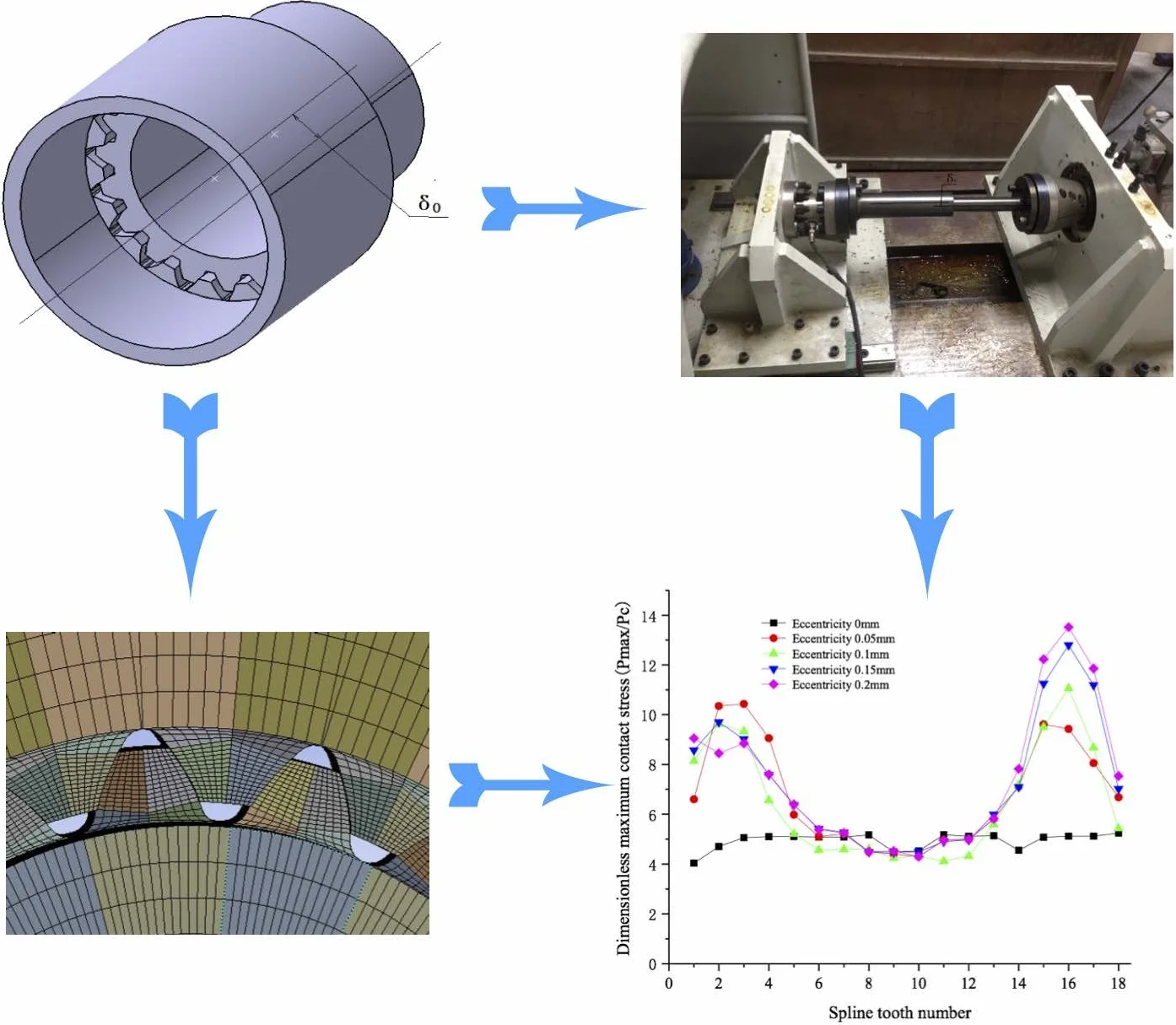
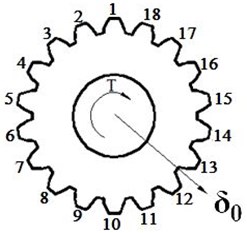
A typical involute spline in agricultural tractor is established according to the data from Table 1, its 3D model and the sectional view are shown in Fig. 1. The eccentricity between the two axes is . The inner spline is made as a driving shaft which end face is fixed; the outer spline is a driven shaft which the end face applies a torque to simulate the actual operating conditions of the spline pair.
Table 1Parameters of involute spline couplings
Parameter | Value |
Number of teeth | 18 |
Modulus (mm) | 2.5 |
Pressure angle (°) | 30º |
Outer spline inner hole diameter (mm) | 20 |
Internal spline shaft outer diameter (mm) | 70 |
Axial contact length of inner and outer splines (mm) | 27 |
Radial contact width (mm) | 2.89 |
(N·m) | 500 |
Elastic modulus (GPa) | 206 |
Poisson’s ratio | 0.3 |
Fig. 1Model of involute spline couplings
a) 3D model
b) Section
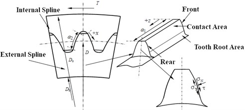
Accordingly, the finite element model is shown in Fig. 2. The hexahedral element is applied in the mesh. In order to improve the mesh quality of the surface, a virtual topology method is also applied. Scanning is adopted for each pair of teeth, so that the entire tooth surface mesh is divided uniformly. the mesh of the inner and outer spline contact sections is refined. After a trial calculation, the number of element is 1995205 and the number of nodes is 4135060, the calculation results tend to converge.
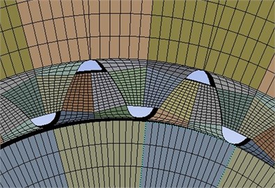
Fig. 2. Element model of involute spline couplings
The contact of the spline pair poses a problem of surface-to-surface contact between elastomers. That is why it is very important to select correctly the material of the contact surface and the target surface, otherwise it will cause too much penetration and will affect the accuracy of calculations. In general, when a convex surface is in touch with a flat or concave surface, the convex surface shall be designated as the contact surface, and the flat or concave surface shall be designated as the target surface. Therefore, the internal spline tooth surface is the target surface, for which the contact surface friction coefficient is 0.3, and the normal stiffness coefficient is 0.1.
3. Results and discussion
3.1. Finite element method results
The nonlinear contact surface can be solved by the augmented Lagrange method, which can meet the contact coordination and automatically adjust the penetration [23]. In addition, the spline tooth surface was calibrated, as shown in Fig. 3.
Fig. 3End view of external spline
For the convenience of analysis, the maximum contact stress and the maximum slip are dimensionless. The dimensionless value of the representative stress is expressed by the ratio of the stress calculated by the finite element method and the average contact stress ; the dimensionless value of the relative slip is expressed by the ratio of the slip calculated by the finite element method and the radial contact width . The average contact stress of the involute spline pair is [24, 25]:
Fig. 4 shows the contact stress and relative slip cloud of the spline pair under axial eccentricity. The abscissa indicates the teeth corresponding to the calibration, and the ordinate indicates the stress value and the slip. It can be seen from the figure that the maximum contact stress is mainly concentrated at the tooth root, and individual tooth stress is relatively large, that is easy to cause failure [26, 27].
Fig. 4Map of involute spline couplings
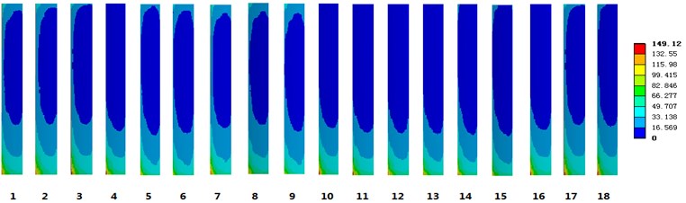
a) Contact stress cloud
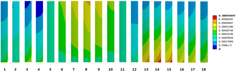
b) Relative sliding cloud
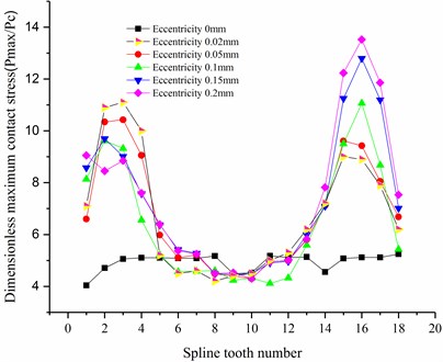
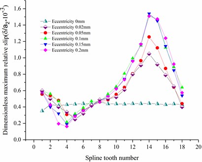
In order to investigate the influence of the eccentricity on the contact characteristics of the involute spline pair, if the size of the element is unchangeable, then the size of the eccentricity is changed only, the influence of contact stress and relative slip of each tooth are calculated, and the calculation results are shown in Fig. 5.
It can be seen from Fig. 5(a) that the maximum contact stress is on the 16th teeth and the 3rd teeth. The stress concentration is available on the 16th teeth because of the combined action of the shaft deviation and the torque, and the increasing stress is available on the 3rd teeth due to the reduced contact area. It can be seen in Fig. 5(b) that the maximum relative slip is located near the 15th teeth, and the relative slip near the 3rd teeth slightly decreases.
In summary, it can be seen that the axis deviation will significantly increase the contact stress and relative slip of the spline pair. A small deviation can cause a sharp increase in contact stress. As the deviation increases, the relative slip increase correspondingly, but the increase is small.
3.2. Experimental results and discussion
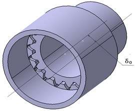
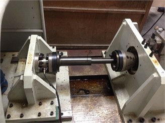
In order to verify the accuracy of the finite element analysis results, in this paper, the effect of the axial displacement is analyzed by making a tribological test. The equipment used in this experiment is a PNW-5 type electro-hydraulic servo test bench. When the spline pair is installed, the axis deviation 0.1 mm, as shown in Fig. 6.
Fig. 5Effect on spline with axis deviation
a) Contact stress line chart
b) Relative slip line chart
Fig. 6Assembly of involute spline couplings with axis deviation
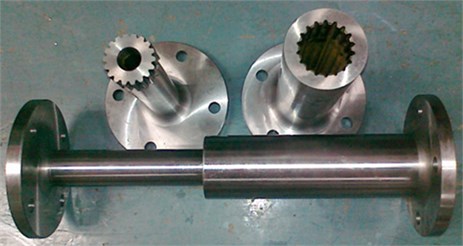
a) Spline coupling
b) Assembling parts
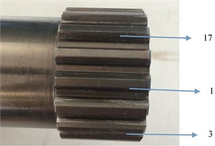
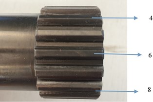
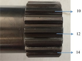
Load the spline coupling to a maximum torque of 3000 N·m, and run until it shows obvious wear spots. The external spline tooth surface and the wear scheme are shown in Fig. 7. The arrows in the figure point at the same number of teeth as the finite element calculation calibration.
It can be seen from Fig. 7, that, when the axis is deviated, the teeth are worn differently, and the tooth root can easily damaged. Particularly, the 2nd and the 3rd teeth are worn rather seriously, the 5th teeth to the 14th teeth are worn rather mildly, and the wear of the 15th teeth and the 16th teeth is the most severe. These results are basically consistent with the finite element theoretical calculations, and verify the tribological characteristics of spline pairs under axial deviation.
3.3. Friction coefficient effect on contact characteristics of involute spline pairs
In order to study the effect of torque on the tribological characteristics of involute spline pairs, the influence of friction coefficient is analyzed under the axial deviation. The deviation of the internal and external splines is set as 0.1 mm, as shown in Fig. 9.
It can be seen from Fig. 9 that the friction coefficient has almost no effect on the maximum contact stress of each tooth, but has a significant effect on the value of slip. The friction coefficient has a low effect on the relative slip of the teeth near the 4th tooth, but has a high effect on the vicinity of the 15th tooth. As the friction coefficient decreases, the maximum relative slip increases significantly, so the value of the friction coefficient should not be too small.
Fig. 7Installation scheme of spline auxiliary shaft deviation
a) 0°
b) 120°
c) 240°
Fig. 8Most severe wear photo
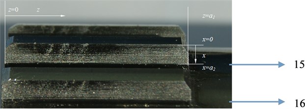
Fig. 9Friction coefficient effect on spline with
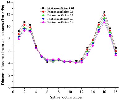
a) Contact stress line chart
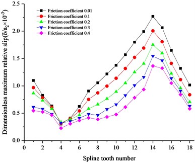
b) Relative slip line chart
4. Conclusions
In this paper, the agricultural tractor spline couplings were studied in condition of axis deviation, and the contact stress and relative slip distributions were analyzed. The conclusions can made as follows:
1) The axial deviation can significantly increase the contact stress and relative slip of the spline pair. As the deviation increases, the contact stress and relative slip increase correspondingly.
2) A small deviation can cause a sharp increase in contact stress. As the deviation increases, the relative slip increases correspondingly, but this increase is rather small.
3) The friction coefficient has almost no effect on the maximum contact stress, but has a significant effect on the value of slip. The value of the friction coefficient shall not be too small.
References
-
Francesca C., Andrea M., Federica A. Fatigue damage in spline couplings: Numerical simulations and experimental validation. Procedia Structural Integrity, Vol. 5, 2017, p. 1326-1333.
-
Andrea Ma, Francesca C., Federica A. Evaluation of graphene grease compound as lubricant for spline couplings. Tribology International, Vol. 117, 2018, p. 162-167.
-
Vincenzo C., Francesca C., Andrea M. Damage identification on spline coupling teeth by means of roughness parameters. Theoretical and Applied Fracture Mechanics, Vol. 82, 2016, p. 9-16.
-
Vincenzo C., Francesca C., Andrea M. Surface characterization of spline coupling teeth subjected to fretting wear. Procedia Engineering, Vol. 74, 2014, p. 135-142.
-
Waqar Q., Francesca, Andrea M. Experimental characterization of roughness parameters for fretting wear in spline couplings. Meccanica, Vol. 52, 2017, p. 1975-1984.
-
Waqar Q., Francesca, Andrea M. Principal component analysis for characterization of fretting wear experiments on spline couplings. Procedia Engineering, Vol. 109, 2015, p. 73-79.
-
Hong J., Talbot D., Kahraman A. Load distribution analysis of clearance-fit spline joints using finite elements. Mechanism and Machine Theory, Vol. 74, 2014, p. 42-57.
-
Nguyen Thanh N., Zhou K., Zhuang X., et al. Isogeometric analysis of large-deformation thin shells using RHT-splines for multiple-patch coupling. Computer Methods in Applied Mechanics and Engineering, Vol. 316, 2017, p. 1157-1178.
-
Yi G., Scott L., Robb W., Robert E., et al. Theoretical and experimental study on gear-coupling contact and loads considering misalignment, torque, and friction influences. Mechanism and Machine Theory, Vol. 98, 2016, p. 242-262.
-
Xiang Z. X., San M. W., et al. Modification methodology of fretting wear in involute spline. Wear, Vol. 368, Issue 369, 2016, p. 435-444.
-
Han B. H. Solid modeling of involute spline shaft. Machinery and Electronics, Vol. 1, 2009, p. 79-80.
-
Li Y. Z., Zhao S. T., Sun Z. Y., et al. Discussion on rationality of efficient and precise batch production process of spline shaft. Forging Technology, Vol. 37, Issue 3, 2012, p. 1-6.
-
Zhao H. M., Li D. Y., Deng W., et al. Research on vibration suppression method of alternating current motor based on fractional order control strategy. Proceedings of the Institution of Mechanical Engineers, Part E: Journal of Process Mechanical Engineering, Vol. 231, Issue 4, 2017, p. 786-799.
-
Zhao H. M., Zheng J., Deng W., et al. Semi-supervised broad learning system based on manifold regularization and broad network. IEEE Transactions on Circuits and Systems I: Regular Papers, Vol. 67, Issue 3, 2020, p. 983-994.
-
Chen Y. Y., Gu Z. Y., Liang Q. Optimization of process parameters affecting bending deformation of spline shaft during cold extrusion. Forging Technology, Vol. 37, Issue 4, 2012, p. 60-63.
-
Zhang Q., Tong N. Y., Wang J. C., Yang K., Chen Chao Experimental research on vibration extrusion forming of spline shaft. Journal of Xi’an Jiaotong University, Vol. 49, Issue 11, 2015, p. 110-115.
-
Hu Z. G., Zhu R. P., Jin G. H. Analysis of fretting frictional contact parameters of aviation involute spline couplings. Journal of Central South University (Science and Technology), Vol. 44, Issue 5, 2013, p. 1822-1828.
-
Hu Z. G., Zhu R. P., Jin G. H. Effect of axial piecewise parabolic modification on fretting wear parameters of involute spline couplings. Journal of Aerospace Power, Vol. 28, Issue 7, 2013, p. 1644-1649.
-
Geng K. H., He J. L., Chen Y., et al. Fatigue optimization analysis of torsion bar spline based on submodel. Journal of Beijing University of Information Science and Technology (Natural Science Edition), Vol. 34, Issue 4, 2019, p. 70-75.
-
Wei P. F., Hao S. N. Stress analysis of spline shaft of sprocket for backhoe loader. Coal Mine Machinery, Vol. 39, Issue 5, 2018, p. 81-82.
-
Deng W., Li W., Yang X. A novel hybrid optimization algorithm of computational intelligence techniques for highway passenger volume prediction. Expert Systems with Applications, Vol. 38, Issue 4, 2011, p. 4198-4205.
-
Deng W., Liu H., Xu J., et al. An improved quantum-inspired differential evolution algorithm for deep belief network. IEEE Transactions on Instrumentation and Measurement, 2020, https://doi.org/10.1109/TIM.2020.2983233.
-
Huang Z. X., Liu C. Z. ANSYS Workbench 14.0 Super study manual. Posts and Telecom Press, Beijing, 2013.
-
Geng X. C., Wang F. G., Wu Y. Z. Program design of geometric parameters calculation of involute spline. Journal of Mechanical Transmission, Vol. 41, Issue 8, 2017, p. 179-187.
-
Bai Z. G. Analysis of spline wear of adapter shaft. China New Technology and Products, Vol. 12, 2019, p. 13-14.
-
Wan Y. P. Causes and improvement measures of root fracture of spline at semi-axle of heavy forklift. Construction Machinery and Maintenance, Vol. 6, 2018, p. 84-85.
-
Huang Z. H., Xia C. G., Hu F. F., et al. Design of hub-to-sleeve spline with variable gauge wheel. Locomotive Electric Drive, Vol. 4, 2018, p. 1-5.
Cited by
About this article

The work described in this paper is fully supported by National Key Laboratory of Science and Technology on Helicopter Transmission(Nanjing University of Aeronautics and Astronautics) (Grant No. HTL-O-20G02); Nanjing Agricultural University Funding (689-rcqd2003-0603); Jiangsu Planned Projects for Postdoctoral Research Funds (2020); the Agricultural Science and Technology Independent Innovation Fund of Jiangsu Province (CX(19)3081) and the Key Research and Development Program of Jiangsu Province (BE2018127). The spline couplings are provided by Nanjing Chuangli Gear Machinery Co., Ltd.
