Abstract
Sliding contact on the contact interface of friction pairs is a common type of contact. The sliding wear caused by sliding contact has an obvious influence on the stress in the contact area. In this study, the photoelastic experiment and finite element method are adopted to study variation laws of stress in the contact area. The results show that the stress in the contact region is very concentrated, and the contact half-width gradually ascends with the increase of sliding wear. The stress intensity in the contact region and von Mises stress at the contact centre decrease with the increase of wear depth. In the case of a wear depth of less than 0.3 mm, the stress intensity and the contact stress decrease rapidly with the growth of wear depth. When the wear depth exceeds 0.3 mm, the influence of wear depth on the stress intensity and contact stress is small. The results of this research clarify the effect of sliding wear on the stress in the contact area, and provide a reference for studying the contact issues.
Highlights
- Photoelastic experiment and finite element method are adopted to research the stress during sliding contact.
- Stress intensity in the contact region is obtained by experimental and numerical calculation methods.
- The influence of sliding wear on the stress is studied.
- Contact characteristics at different wear depths are gotten.
1. Introduction
Sliding wear, also known as adhesive wear, is a complex frictional process occurring when two surfaces experience relative motion. This wear mechanism is omnipresent in industrial engineering, affecting the efficiency and longevity of critical components such as gears, bearings, and other friction pairs. The mechanism that causes sliding wear is the adhesion of the contact surface. When relative motion occurs, this adhesion will cause deformation, material transfer, and eventually wear.
Sliding wear has profound influences on diverse industries. Taking wheel/rail contact as an example, the sliding contact between wheel and rail will occur during the braking process of a train. The train braking will cause serious wear to the wheel surface (Fig. 1). Wear changes the geometry of the contact surface, directly affecting the stress distribution, which also affects the train braking frictional heat, thermal fatigue and material damage on the contact surface [1]-[4]. In this paper, the effect of sliding wear on stress are studied through experiment and numerical calculation.
The wear on the interface is significant when the friction pair is in the sliding contact. Bowden and Taber conducted extensive studies on contact and friction between friction pairs [5]. And a large number of research results are widely used in a variety of fields. Archard established the Archard wear theory, which can be adopted to analyze the wear of various contact pairs during contact [6]. In addition, scholars conducted many fundamental studies on the contact and friction of friction pairs [7]-[11]. Compared to other wear theories, Archard's theory is a simple and practical model, and can be applicable to various wear conditions and different materials, exhibiting broad applicability [12]-[14].
The main theories for calculating the contact issues include Hertz contact theory [15], Carter two-dimensional contact theory [16], Vermeulen-Johnson contact theory [17], and Kalker theory [18]. The above theories usually assume the contact stress on the interface is semi-ellipsoidal or quadratic parabolic. However, sliding wear significantly changes the contact surface geometry and also affects the distribution form of contact stress when the friction pair is in sliding contact.
Fig. 1Damage to wheel tread
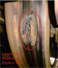
a) High-speed railway
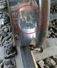
b) Normal-speed railway
In actual contact components, it is almost impossible to directly observe the changes in contact stress. Photoelastic technology provides a non-intrusive, highly sensitive stress analysis method. By measuring optical distortions on material surfaces, it precisely reveals stress distribution caused by wear, providing insightful understanding of material performance and wear mechanisms [19]-[21]. In this paper, photoelastic experiment and finite element method are employed to research the stress during friction pair sliding contact. The research results can clarify the effect of sliding wear on the stress, and provide a reference for studying the other contact issues.
2. Method
2.1. Photoelastic experiment
The photoelastic method is an experimental method that can provide information about the full-field stress distribution. The photoelastic streak map contains two important physical quantities, namely isobars and isotropes [22], and the photoelastic experiment can present the stress distribution law in the contact region very well [23]-[26]. Fig. 2 is the sketch of the circularly polarized light field arrangement. During the photoelastic experiment, the incident light will be decomposed into two beams of polarised light along the two principal stresses when it passes through the birefringent material. Due to the different propagation velocities of the two beams of polarised light, a phase difference of ∆ will generate when it is ejected from the specimen. The birefringence is proportional to the applied stress according to the law of planar stresses-optics. That is:
where is the material optical constant. and are the first and third principal stress. is the thickness of the specimen. is the wavelength of the incident light.
When incident light with an intensity of passes through the detector mirror, the intensity of light is:
From Eqs. (1) and (2), it can be seen that two beams of polarised light with a phase difference will produce interference fringes. While there is no phase difference when the principal stress are equal, in which case dark fringes will appear. The more concentrated the stress on the specimen, the greater the change in the principal stress difference, and therefore the denser the interference fringes, and vice versa. The information from the interference fringes can be used to characterize the stress distribution in the specimen. The relationship between stress intensity and principal stresses is:
Fig. 2Sketch of circularly polarized light field arrangement
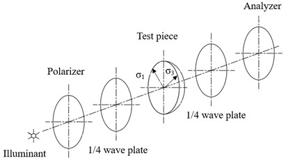
Fig. 3Sliding wear finite element model
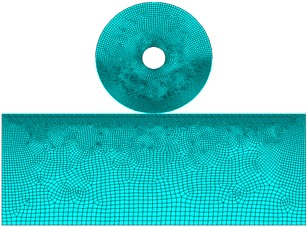
2.2. Numerical model
In this paper, a sliding wear finite element model is built, and is shown in Fig. 3. In the model, the friction pair is simulated with PLANE182 element, and the contact behaviour is simulated with the CONTA171 and TARGE169 elements. The model has a total of 13411 elements and 13350 nodes. After trial and error, the minimum element size is set to 0.15 mm under the conditions of meeting calculation speed and accuracy. Meanwhile, the wear elements are created based on the Archard wear theory. The wear can be calculated by:
where is the amount of wear per unit area per unit time, or is called the wear rate. is the wear coefficient. is the sliding speed. is the hardness of the material. And is the contact stress. In the finite element model, the extended Lagrangian algorithm is used to calculate the contact stress [27]. The expression is:
where is the normal contact stiffness, is the contact gap, is:
where is the intrusion tolerance, is the Lagrange multiplier component of the -th iteration step.
2.3. Analysis parameter
In the experiment, the photoelastic specimen consists of a hollow circle and a rectangle, and they are made of epoxy resin. The inner and outer diameter of the hollow circle is 10 mm and 50 mm, respectively. The height and length of the rectangle is 50 mm and 130 mm, respectively. The thickness of the specimen is 6 mm (Fig. 4). In the finite element wear model, the dimensions of the contact pair are the same as the photoelastic specimen. The vertical displacement at the bottom of the rectangle is constrained [28]. The modulus and Poisson’s ratio of the material is 3 GPa and 0.38, respectively, and the density is 1200 kg/m3. The wear coefficient is 4×10⁻⁴ [29], and the hardness is 85 HD. The vertical load applied on the top of the hollow circle is the same as that of the photoelastic experiment, both are 100 N. The sliding speed is 1 m/s.
Fig. 4Photoelastic experiment
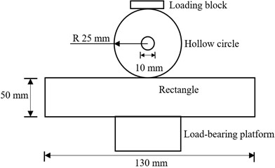
a) Schematic diagram of photoelastic experiment
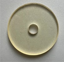
b) Hollow circle
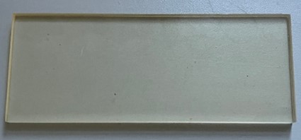
c) Rectangle
3. Results
3.1. Experiment results
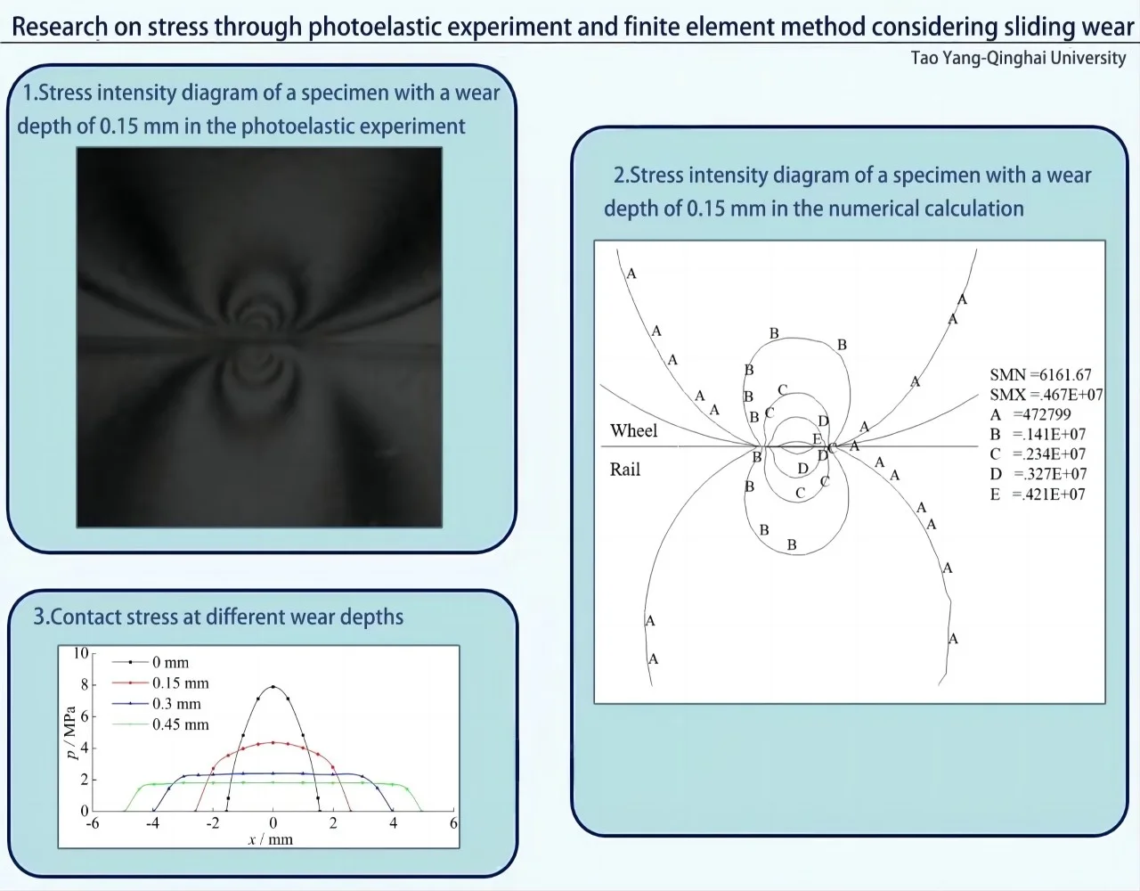
The stress intensity at different wear depths are illustrated as Fig. 5. Fig. 5(a) shows the photoelastic stripes are symmetrically distributed, with a closed-curve distribution at the position of the contact centre. And the number of stripes is the most intensive, in other words the stress is very concentrated. Fig. 5(a) also shows the stripe gap gradually increases from the contact centre outwards, and it indicates the stress in the contact centre is the highest, and decreases gradually from the contact centre outwards. Fig. 5(b), Fig. 5(c) and Fig. 5(d) show that as the depth of wear increases, the number of stripes near the contact surface decreases, and the gap between the stripes increases.
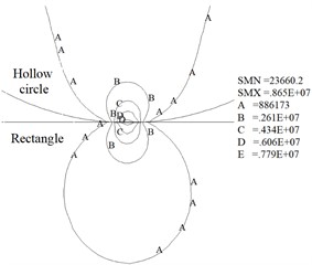
Fig. 5Stress intensity diagram at different wear depths
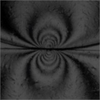
a) Unworn (0 mm )
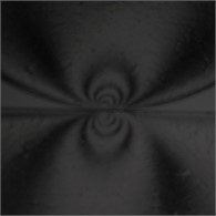
b) 0.15 mm
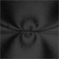
c) 0.3 mm
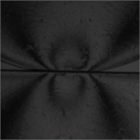
d) 0.45 mm
3.2. Finite element calculation results
Stress intensity contours obtained by finite element model are shown as Fig. 6. The contact half-widths, contact stress and von Mises stress at the contact centre under the condition of different wear depths are respectively shown as Fig. 7, Fig. 8 and Fig. 9.
Fig. 6Stress intensity contour maps at different wear depths (Pa)
a) Unworn (0 mm)
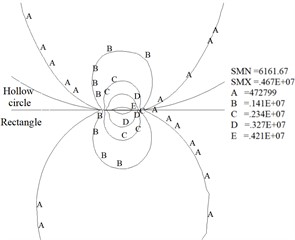
b) 0.15 mm
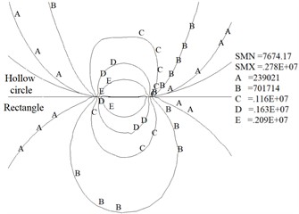
c) 0.3 mm
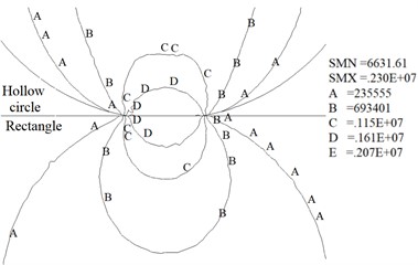
d) 0.45 mm
Fig. 6 shows the maximum stress intensity for the four cases of wear depth of 0 mm, 0.15 mm, 0.3 mm and 0.45 mm is 8.65 MPa, 4.67 MPa, 2.78 MPa and 2.3 MPa, respectively. The results indicate the maximum value of stress intensity decreases rapidly with the growth of the wear depth. Fig. 6 also shows the shape of the contour line near the contact surface is gradually flat with the increase of wear depth. Meanwhile, the results show the stress distribution laws obtained from numerical calculation are consistent with the experimental results (Fig. 5 and Fig. 6).
Fig. 7Contact half-width at different wear depths
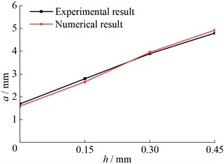
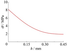
Fig. 7 shows with the growth of wear depth (), the contact half-width () on the contact surface gradually increases. Moreover, Fig. 7 shows the results obtained from the finite element wear model fit well with the experimental results. Fig. 8 shows as the depth of wear increases, the contact stress on the contact surface is gradually transformed from the initial sharp convex distribution to a flat shape, the contact size is gradually increasing, and the maximum contact stress is gradually decreasing. In other words, the distribution of contact stress gradually becomes uniform. Fig. 9 shows the von Mises stress in the contact centre descends with the increase of the wear depth. And when the wear depth is more than 0.3 mm, the influence of wear on the von Mises stress is small.
Fig. 8Contact stress at different wear depths
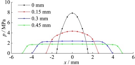
Fig. 9Von Mises stress at contact centre
4. Conclusions
Sliding contact is a common contact phenomenon in friction devices. In the sliding contact process, the wear and contact stress on the contact interface will change significantly. The change rule of stress on the contact surface at different wear depths is analyzed by photoelastic experiment and numerical calculation, and the conclusions are as follows.
1) At different wear depths, the photoelastic stripes are symmetrically distributed and are very dense in the contact area, indicating that the stress is concentrated in the contact region. As the wear depth increases, the number of photoelastic stripes decreases and the distance between the stripes gradually increases.
2) As the wear depth increases, the contact size increases, the stress intensity in the contact region and the von Mises stress of the contact centre rapidly decrease, and the contact stress distribution gradually become uniform.
3) When the wear depth is less than 0.3 mm, the contact stress on the contact surface will decrease rapidly as the wear depth increases. If the wear depth is greater than 0.3 mm, the effect of the wear depth on the stress intensity and contact stress gradually decreases.
5. Discussion
The effect of sliding wear on the stress in the contact area is investigated in this article by experimental and numerical methods. The small-scale models are used, and how to apply the research results to actual components is a challenge. Therefore, a mathematical model of contact stress considering wear is hopefully established to reflect the changes in contact stress during sliding wear, and research in this aspect is currently underway.
References
-
X. Wang et al., “Peridynamic modeling of rail wear during sliding contact considering thermal effects,” Wear, Vol. 532-533, p. 205110, Nov. 2023, https://doi.org/10.1016/j.wear.2023.205110
-
L. J. Mao, X. He, M. J. Cai, and L. Q. Qian, “Influence of contact load on the dry sliding wear performance of 7075 aluminum alloy,” Experimental Techniques, Vol. 47, No. 2, pp. 357–367, Feb. 2022, https://doi.org/10.1007/s40799-022-00551-y
-
Z. Zhou et al., “Dynamic response feature of electromechanical coupled drive subsystem in a locomotive excited by wheel flat,” Engineering Failure Analysis, Vol. 122, p. 105248, Apr. 2021, https://doi.org/10.1016/j.engfailanal.2021.105248
-
S.-Y. Zhang et al., “Study on wear and rolling contact fatigue behaviours of defective rail under different slip ratio and contact stress conditions,” Tribology International, Vol. 169, p. 107491, May 2022, https://doi.org/10.1016/j.triboint.2022.107491
-
M. E. Merchant, The Friction and Lubrication of Solids. Oxford: Clarenden Press, 1964.
-
J. F. Archard, “Contact and rubbing of flat surfaces,” Journal of Applied Physics, Vol. 24, No. 8, pp. 981–988, 1953, https://doi.org/10.1063/1.17214483
-
J. X. Li et al., “Wear and damage behaviours of wheel and rail materials: effects of friction modifier and environmental temperature,” Wear, Vol. 523, p. 204796, Jun. 2023, https://doi.org/10.1016/j.wear.2023.204796
-
Q. Lian et al., “Thermo-mechanical coupled finite element analysis of rolling contact fatigue and wear properties of a rail steel under different slip ratios,” Tribology International, Vol. 141, p. 105943, Jan. 2020, https://doi.org/10.1016/j.triboint.2019.105943
-
Y. B. Huang, L. B. Shi, X. J. Zhao, Z. B. Cai, Q. Y. Liu, and W. J. Wang, “On the formation and damage mechanism of rolling contact fatigue surface cracks of wheel/rail under the dry condition,” Wear, Vol. 400-401, pp. 62–73, Apr. 2018, https://doi.org/10.1016/j.wear.2017.12.020
-
C. C. Fang, S. A. Sulaiman, W. Zhou, H. K. Yan, J. Chen, and X. H. Meng, “Wheel-rail contact and friction models: A review of recent advances,” Proceedings of the Institution of Mechanical Engineers, Part F: Journal of Rail and Rapid Transit, Vol. 237, No. 10, pp. 1245–1259, 2023, https://doi.org/10.1177/0954409723115673
-
M. Neslušan et al., “Microstructural transformation of a rail surface induced by severe thermoplastic deformation and its non-destructive monitoring via barkhausen noise,” Wear, Vol. 402-403, pp. 38–48, May 2018, https://doi.org/10.1016/j.wear.2018.01.014
-
S. Wen and P. Huang, Principles of Tribology. Beijing: Tsinghua University Press, 2002.
-
R. Aghababaei and K. Zhao, “Micromechanics of material detachment during adhesive wear: A numerical assessment of Archard’s wear model,” Wear, Vol. 476, p. 203739, Jul. 2021, https://doi.org/10.1016/j.wear.2021.203739
-
X. Guo et al., “Friction-wear failure mechanism of tubing strings used in high-pressure, high-temperature and high-yield gas wells,” Wear, Vol. 468-469, p. 203576, Mar. 2021, https://doi.org/10.1016/j.wear.2020.203576
-
Valentin L. Popov, Contact Mechanics and Friction: Physical Principles and Applications. London: Springer, 2010.
-
F. W. Carter., “On the action of a locomotive driving wheel,” Proceedings of the Royal Society of London. Series A, Containing Papers of a Mathematical and Physical Character, Vol. 112, No. 760, pp. 151–157, Aug. 1926, https://doi.org/10.1098/rspa.1926.0100
-
P. J. Vermeulen and K. L. Johnson, “Contact of nonspherical elastic bodies transmitting tangential forces,” Journal of Applied Mechanics, Vol. 31, No. 2, pp. 338–340, Jun. 1964, https://doi.org/10.1115/1.3629610
-
J. J. Kalker, “On the rolling contact of two elastic bodies in the presence of dry friction,” Delft University, Netherlands, 1967.
-
M. Ragulskis and L. Ragulskis, “Plotting isoclinics for hybrid photoelasticity and finite element analysis,” Experimental Mechanics, Vol. 44, No. 3, pp. 235–240, Jun. 2004, https://doi.org/10.1177/0014485104044315
-
Z. Ren et al., “Quantification of the stress field in extremely complex pores by digital photoelasticity,” Measurement, Vol. 220, p. 113343, Oct. 2023, https://doi.org/10.1016/j.measurement.2023.113343
-
Z. Ren, H. Xie, and Y. Ju, “Determination of the stress and strain fields in porous structures by photoelasticity and digital image correlation techniques,” Polymer Testing, Vol. 102, p. 107315, Oct. 2021, https://doi.org/10.1016/j.polymertesting.2021.107315
-
K. Ramesh and G. Lewis, “Digital photoelasticity: advanced techniques and applications,” Applied Mechanics Reviews, Vol. 55, No. 4, pp. B69–B71, Jul. 2002, https://doi.org/10.1115/1.1483353
-
B. R. Mose, D. K. Shin, and J. H. Nam, “Experimental stress analysis of spherical roller bearing for high-speed trains using photoelasticity,” Experimental Techniques, Vol. 47, No. 3, pp. 669–678, May 2022, https://doi.org/10.1007/s40799-022-00576-3
-
L. Chen, M. Zhang, D. Li, and Y. Li, “Visualization and quantification of the stress distribution on epoxy resin through photoelasticity and infrared radiation techniques,” AIP Advances, Vol. 12, No. 1, p. 01531, Jan. 2022, https://doi.org/10.1063/5.0074643
-
A. W. Hussein and M. Q. Abdullah, “Experimental stress analysis of enhanced sliding contact spur gears using transmission photoelasticity and a numerical approach,” Proceedings of the Institution of Mechanical Engineers, Part C: Journal of Mechanical Engineering Science, Vol. 237, No. 18, pp. 4316–4336, Jan. 2023, https://doi.org/10.1177/09544062231152158
-
K. V. N. Surendra and K. R. Y. Simha, “Characterizing frictional contact loading via isochromatics,” Experimental Mechanics, Vol. 54, No. 6, pp. 1011–1030, Mar. 2014, https://doi.org/10.1007/s11340-014-9865-3
-
Y. Wu, Y. Wei, Y. Liu, Z. Duan, and L. Wang, “3-D analysis of thermal-mechanical behavior of wheel/rail sliding contact considering temperature characteristics of materials,” Applied Thermal Engineering, Vol. 115, pp. 455–462, Mar. 2017, https://doi.org/10.1016/j.applthermaleng.2016.12.136
-
Y. Wei, Y. Wu, and Z. Chen, “An experimental measurement and numerical calculation method on friction temperature rise of sliding contact pairs – taking rail/wheel contact as an example,” Journal of Measurements in Engineering, Vol. 11, No. 1, pp. 1–11, Mar. 2023, https://doi.org/10.21595/jme.2023.22974
-
X. K. Li, Z. K. Li, X. Li, J. Y., Wang, and H. Y. Li, “Preparation of PAO10@SiO2 nanocapsules and tribological properties of self-lubricating epoxy composites,” Polymer Materials Science and Engineering, Vol. 39, No. 1, pp. 50–56, 2023, https://doi.org/10.16865/j.cnki.1000-7555.2023.0010
About this article

This research is supported by the Qinghai Youth Natural Science Foundation of China (Grant No. 2022-ZJ-960Q), and is also sponsored by National Natural Science Foundation of China (Grant No. 51236003).
The datasets generated during and/or analyzed during the current study are available from the corresponding author on reasonable request.
Tao Yang: Data curation, Software, Original Draft Preparation and Editing. Yunpeng Wei: Conceptualization, Methodology, Reviewing, Editing and Funding Acquisition. Jihao Han: Data curation and Software. Zhidong Chen: Supervision and Software.
The authors declare that they have no conflict of interest.
