Abstract
Gear transmission is the principal power transmission mode of many machine, the reliability of transmission system has important influence on the accomplishment of daily task. This paper made a gear transmission system as the research object, we build the two-stage gear transmission system model and calculate its dynamic response in theory. Then, we study the mesh stiffness of gear concerning the variation of the mesh position from the gear transmission system. On the basis of these work, we establish the gear system’s finite element simulation model considering the tooth contact of internal gear system. After the simulation, we had get the contact response and the time history of some important area’s equivalent stress. Through these work, we can study the contact stress of the two-stage gear system in theory method and finite element simulation method, which has a guiding significance on the optimum structural design of two-stage transmission gear system.
1. Introduction
The gear transmission system is a common mechanical component and is widely used to transmit power and change speed and/or direction in many kinds of mechanical equipments such as the self-propelled gun. The majority of mechanical failures of the weapon are caused by the transmission system failures. In order to reduce these mechanically induced failures and excessive maintenance, it is vital to accurately identify the faults and predict the fatigue life in the mechanical system. As an important part of the gear transmission system, the two-stage gear transmission system is a typical component. The two-stage gear transmission system is the basic part of the self-propelled gun gearbox and will reflect the main characteristics of the whole transmission system. From the experience of usage, the surface fatigue failures due to rolling and sliding contact are the most important problems in the gear transmission system. Under rolling and sliding contact, various surface damages like pitting, agglutination, spalling and scoring will occur and lead to loss of major functions.
Modelling studies of gear teeth contact based on engineering mechanics have been carried out by several researchers in the past. Literature [1, 2] build gear dynamic models based on the vibration model of gear rotor system, with which the gear meshing force, dynamic load coefficient and the correction coefficient were studied. Recently, in the area of cylindrical gear system [3, 4], spiral bevel gear system [5-7] and planetary gear system [8-10], considering the time-varying meshing stiffness, mesh damping, manufacturing error, surface friction and other factors, there are many gear transmission systems had been established. Furthermore, with the method of Runge-Kutta, Gill integral, harmonic balance, finite element to solve the dynamic model and get the single cycle harmonic, multi cycle non-harmonic, quasi periodic and chaotic response and steady-state response, analyze the impact of different parameters of gear meshing impact state, the nonlinear dynamical behaviors and parameters on the dynamic characteristics of the system.
The above literature has achieved many valuable research results, but the research object is often a single gear transmission form, the research of the coupled nonlinear vibration characteristics on the multi-stage gear transmission system is relatively few. In this paper, aim at the characteristics of multistage gear transmission, considering various influence factors comprehensively, we build the nonlinear dynamic model of the two-stage gear transmission system and get the dynamic response, study the change rule of the mesh stiffness. Furthermore, we build the finite element model of the meshing gear and analysis the contact stress during the operation period considering the contact friction. Through the work, we can get the contact status and locate the dangerous position of the gear, which has a guiding significance on the optimum structural design of gearbox of self-propelled gun.
2. Theory model of the gear system
2.1. Structure of the gear system
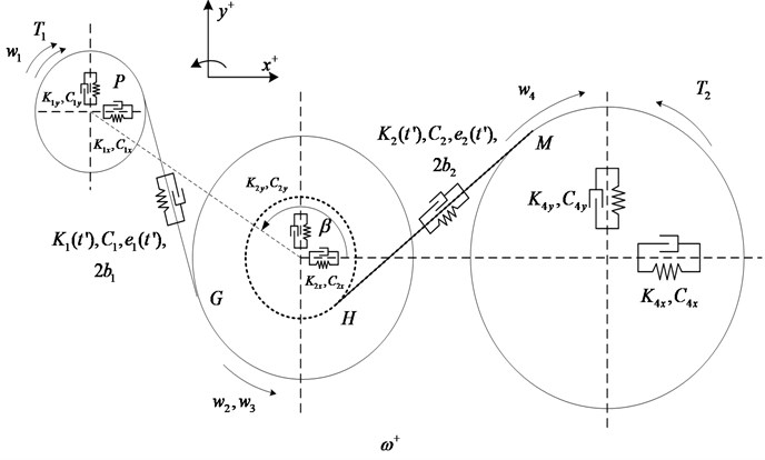
The structure of gear transmission system we had analysis as show in Fig. 1. This system contains four gears (input initiative gear, intermediate passivity gear, intermediate initiative gear and output passivity gear), three drive shafts and corresponding bearings. The type of input bearing is 6305, the type of intermediate bearing is 6206 and the type of output bearing is 6209.
Fig. 1The structure of multistage gear system
As shown in Table 1, we can see the parameters of two stage gear transmission system, we numbered the four gears as 1-4, and the 1st gear is the input initiative gear, the 2rd gear is the intermediate initiative gear, the 3rd gear is the intermediate passivity gear, the 4th gear is the output passivity gear.
Table 1Parameters of two stage gear transmission system
Gear | Teeth | Module | Tooth width(mm) |
1 | 25 | 2 | 45 |
2 | 50 | 2 | 25 |
3 | 19 | 2.5 | 50 |
4 | 81 | 2.5 | 25 |
2.2. Theory analysis on the dynamic response of the system
As shown in the gear system structure figure, , , , are the multistage gear system’s bearing stiffness and damping of the gear pair; , , are the time-varying meshing stiffness, mesh damping, transmission error and the interval between the tooth; is the angular velocity of each gear; , is the input torque and the load torque; is the angle between the direction of the first line and a horizontal center of gear pair. The dynamic model is a two-dimensional plane vibration system, the gear 2, 3 has the same translational and rotational degree of freedom. Therefore, the model has 9 degrees of freedom, for the three gear shaft center along the direction of translational freedom degrees and around the respective axis rotational degrees of freedom, they are expressed as , , , , , , , , , introduced into the mesh points along the meshing line direction relative displacement is , relative displacement of meshing point , along the contact line is , then the dynamic response of the gear transmission system can be expressed as:
where is the time-varying mesh stiffness with 1, 2; is the function of gear interval with 1, 2; is the gear transmission error with 1, 2; is the gear’s radius with 1, 2, 3, 4; and are the mesh angle of gear; is the equivalent mass of the gear and shaft, , , .
2.3. Mesh stiffness analysis on the system
Caption in generally, the meshing contact ratio of gear system is bigger than 1, the number of teeth which participant the meshing process will change along time periodicity. In addition, due to the flexibility of tooth, as the change of meshing position, the mesh stiffness will change as time goes on. These factors make the mesh stiffness a metamorphic value along the time, that is the so called stiffness excitation which will influence the mesh force and the dynamic response of the gear transmission system.
On the basis of the mesh stiffness calculation model from Y. Cai [11, 12], we can get the mesh stiffness of a pair gear:
where is the overlap coefficient, is the overlap coefficient on the end face, is the normal modulus of gear joint, is the total depth, is the mesh time on the end face.
Number the mesh gear, 1, 2, 3…, set the first mesh time as 0, go through the next pair gears start mesh and the first pair finish the mesh at ,and the next pair gears finish the mesh after another . We can get , and when , the comprehensive mesh stiffness is:
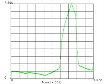
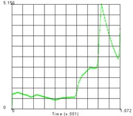
On the basis of the Eq. (2) and Eq. (3), we can get mesh stiffness curve of the first and second pair of gear system as shown in the Fig. 2.
Fig. 2Time-varying mesh stiffness of the first and second pair of gears
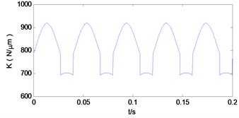
a) The first pair of gears
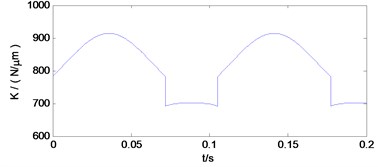
b) The second pair of gears
3. Contact stress simulation of the system
In this paper, we use MSC.Marc to establish the finite element model of the mesh gear. This software has powerful function on the model’s establishment, mesh seeds distribution and many kinds of connector for data exchange. It has the before processing module and after processing module, these two processing modules have very strong surface mesh and grid division ability, in addition, they equipped with a variety of well-known CAD and CAE software to exchange geometric models and finite element models.
3.1. Finite element model generation
Reasonably dividing the finite element mesh is the guarantee to complete the finite element analysis. The grid form and quantity of the division will have a direct impact on the calculation accuracy and the calculation scale. Generally speaking, the number of the grid is increasing, the accuracy of the calculation will be improved, but also the calculation time will increase. Therefore, when determining the number of the grid should considering two factors, they are the mesh density and the element type. Mesh density refers to the different parts of different size of the grid structure, which is in order to adapt to the characteristics of data distribution calculation. The choice of element type has a great influence on the calculation results. In order to improve the accuracy of calculation to obtain better results, this paper adopt eight node hexahedron element to mesh the gear.
In order to mesh the model by the hexahedral element, the work must be divided into four steps:
The first step is to generate the cutting surface that describes the model. The second step is to generate a surface triangle or quadrilateral element. The software needs these discrete units surface to describe the network boundary geometry information. The third step is making the surface closing. The fourth step is set the grid partition parameters, complete the work.
3.2. Simulation results
Since the two teeth are defined as the flexible body, the contact will make them deformed, and thus the setting includes a large deformation option. Using explicit algorithm, the central difference method is used to select the LUMP parameters to generate the cluster mass matrix. Then, the dynamic response of the passive gear is analyzed, and the stress state distribution of 9.600E-005s and 7.840E-004s as shown in Fig. 3.
Fig. 3Stress response of gear tooth contact
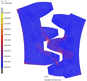
a) 9.600E-005 s
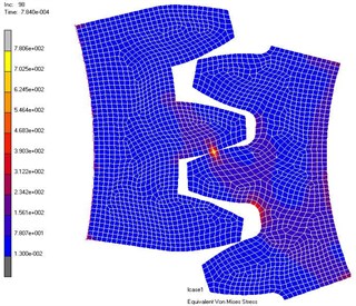
b) 7.840E-004 s
Fig. 4Diagrammatic sketch of driven gear’s node distribution
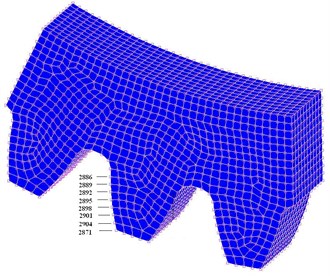
The distribution of the nodes is shown in the Fig. 4 and the equivalent stress time histories of each node are shown in the Fig. 5. From these two figures we can get the equivalent stress time course and the corresponding region on the teeth. From the results we can see that the maximum stress area appears in the contact position of the tooth surface, which is consistent with the actual working condition. The maximum contact stress is obtained at the node 2889, which is 780.6 MPa.
4. Conclusions
This paper establishes the theory model of a certain two-stage gear transmission system with some reasonable assumptions and a time-varying mesh stiffness analytical model is adopted to replace the fixed mesh stiffness before so that the results will be more accurate. On the basis of the theory model, the finite element simulation model of the pair of meshing gear had been established. From the simulation results, we get the stress response of the gear system and find the dangerous position on the teeth of the gear system, we can find out that the stress on the dangerous position is in the security scope or not. It has a guiding significance on the optimum structural design of gear transmission system. Next, we can calculate the fatigue life of transmission system with the stress response we get in this work.
Fig. 5Time history of each node’s equivalent stress
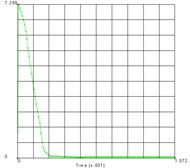
a) Node 2871
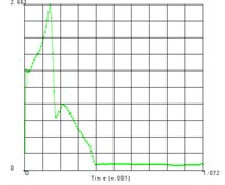
b) Node 2904
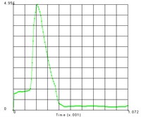
c) Node 2901
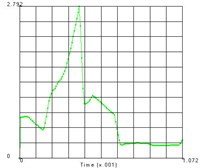
d) Node 2898
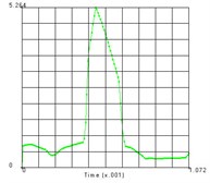
e) Node 2895
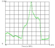
f) Node 2892
g) Node 2889
h) Node 2886
References
-
Dou W., Zhang N., Liu Z. S. The coupled bending and torsional vibrations of the high-speed geared rotor-bearing system. Journal of Vibration Engineering, Vol. 4, 2011, p. 385-393.
-
Yang X. Y., Zhou X. J., Hu H. W. Nonlinear vibration characteristics of helical bevel gear system and parameters influences. Journal of Zhejiang University (Engineering Science), Vol. 3, 2009, p. 28-32.
-
Bonori G., Pellicano F. Non-smooth dynamics of spur gears with manufacturing errors. Journal of Sound and Vibration, Vol. 2, 2007, p. 271-283.
-
Liu G., Parker R. G. Impact of tooth friction and its bending effect on gear dynamics. Journal of Sound and Vibration, Vol. 5, 2009, p. 1039-1063.
-
Lin T. J., Yang Y. N., Li R. F. Numerical simulation of the internal dynamic excitation of a spiral bevel gear transmission. Journal of Chongqing University, Vol. 6, 2009, p. 609-613.
-
Li M., Hu H. Y. Steady state response of the coupled lateral-torsional vibrations of geared rotor system under aholonomic constraint. Journal of Vibration Engineering, Vol. 1, 2003, p. 79-84.
-
Li M. F., Lim T. C., Shepard W. S. Modeling active vibration control of a geared rotor system. Smart Materials and Structures, Vol. 3, 2004, p. 449-458.
-
Xu L. X., Li Y. G. Effects of bearing clearance and flexibility on the dynamic errors of mechanisms. Chinese Journal of Mechanical Engineering, Vol. 7, 2012, p. 30-36.
-
Cheng Z., Hu N. Q., Gao J. W. Prognosis of fatigue crack in planetary gear sets based on physical model and modified gray theory. Journal of Mechanical Engineering, Vol. 9, 2011, p. 79-84.
-
Heege A., Betran J., Radoveic Y. Fatigue load computation of wind turbine gearboxes by coupled finite element, multi-body system and aerodynamic analysis. Wind Energy, Vol. 5, 2007, p. 395-413.
-
Cai Y. Simulation on the rotational vibration of helical gears in consideration of the tooth separation phenomenon (A new stiffness function of helical involutes tooth pair). Journal of Mechanical Design, Vol. 9, 1995, p. 460-468.
-
Cai Y., Hayashi T. The linear approximated equation of vibration of a pair of spur gears (Theory and experiment). Journal of Mechanical Design, Vol. 6, 1994, p. 558-564.
About this article

