Abstract
The wide application of large inertia loads in space drive mechanisms is relatively rare in theoretical research. An 8-degree-of-freedom nonlinear dynamic model is established for the time-varying and nonlinear perturbation problems of a large inertia load space drive mechanism. The model is a two-stage spur gear model in which the effects of backlash and time-varying stiffness are considered. The 3D model was imported into ADAMS, and the nonlinear dynamic response of the system was studied by motion simulation. This paper sets up a large inertia experimental device to collect and process data. Comparing experimental results with Adams results, the correctness of the numerical model was verified, and the reasons for the differences between the two were explained. A comparative analysis of the load response under different inertia was performed to illustrate the importance of studying large inertia loads. The simulation results show that the output shaft has a great influence on the dynamic response. Changing the material of the gear can improve the transmission precision of the gear system. The analysis results in this paper enrich the research on the dynamic response of gear system, and provide a theoretical basis for the subsequent design of large inertia load gear system and improve vibration and noise during operation.
Highlights
- An 8-degree-of-freedom nonlinear dynamic model is established for the time-varying and nonlinear perturbation problems of a large inertia load space drive mechanism.
- The 3D model was imported into ADAMS, and the nonlinear dynamic response of the system was studied by motion simulation.
- Changing the material of the gear can improve the transmission precision of the gear system.
- For the gear pair, the use of titanium alloy material can greatly reduce the amplitude of the stiffness fluctuation at the time of meshing, which is conducive to gear transmission accuracy.
1. Introduction
Gears are one of the most widely used mechanical components in mechanical equipment. Gear systems are often used to slow down and increase the available torque, changing the direction of energy transfer. With the wide application of large inertia loads in space drive mechanisms, large inertia brings new problems and challenges to the life, reliability and safety of spacecraft design.
The analysis of the dynamic characteristics of the large inertia load space drive mechanism is less relevant in the theoretical research, which mainly utilizes simulation technology for both analysis and research. Xi’an Research Institute of China Electronics Technology Group Co., Ltd. carried out calculation and dynamic simulation of the torsional vibration resonance frequency of the antenna base drive system [1]. The backlash has strong nonlinear characteristics, so its influence on the gear dynamics as internal excitation is very complicated [2-4]. Linear dynamic models are not sufficient to describe the dynamic response of mechanical mechanisms, and nonlinear models must be established [5-7]. Considering the time-varying characteristics of the backlash, Cai [8] proposed a nonlinear model, which is characterized by zero dynamic force when the teeth are not in contact. Litak and Friswell [9] studied the dynamic response of the torsion model of a single-stage gear. The study shows that the nonlinear dynamic response is affected by external excitation. During the meshing process, the number and stiffness of the contact teeth change with time, and the dynamic equation is established based on the elastic theory. The dynamic performance of the gear can be obtained by given parameters [4, 10]. Kahraman [4] proposed a torsional impact model in which the elastic tooth contact is modeled by a time-varying stiffness spring. Shen [11] analyzed the nonlinear dynamics model of gear system including time-varying stiffness and backlash using incremental harmonic balance method. Gear systems for the industrial sector are typically two or more stages to ensure maximum torque [12]. Lassâad Walha [13] established a 12-degree-of-freedom nonlinear dynamic model for a two-stage gear system characterized by the addition of time-varying stiffness and backlash, and the nonlinear system is decomposed into several linear system by Newmark [14] iterative algorithm.
Tianfu Yang [15] considered the impact of a high reduction ratio and studied the dynamic characteristics of the space manipulator, whereas the characteristics of the large inertia load were not analyzed. Zhigang Xu [16] proposed an equivalent simulation method for an excessively large inertia load, simulating the large moment of inertia required by the space manipulator and verified the effectiveness of the method by numerical simulation under different working conditions. Chen Shiqi [17] established a bending – torsion coupling nonlinear dynamic model of a low speed overload planetary gear drive system with friction and studied the effect of friction on the nonlinear dynamic behavior of a low speed overload gear transmission. Ahmed Hammami [18] developed a model of planetary gear torsional concentrated parameter with dynamic recirculation and studied the nonlinear behavior under variable load conditions. In this paper, the large inertia load-space drive mechanism gear reduction system was utilized for the driving of a satellite sun wing. Since the sun wing is required to be changed in real time, according to the position of the sun, the mechanism is required to start and stop frequently at low speed. An apparent phenomenon of disturbance when the mechanism is stopped exists. Therefore, in this paper, the effects of large inertia load torque on the system were focused on.
In this paper, for the time-varying and nonlinear perturbation problems of a large inertia load space drive mechanism, the two-stage spur gear system is taken as the research object, and the dynamic model considering backlash is established, and the kinematics simulation software Adams is used to analysis dynamic characteristics and load response. The Adams analysis has drawn some conclusions, which enriched the research on large inertia loads, and provided an important reference for the actual design of the gear system.
2. Establishment of dynamic model
Regarding the dynamic modeling of the two-stage spur gear deceleration system of the inertial load space drive mechanism, it is assumed that the mass, the moment of inertia, the radius and the average meshing stiffness of each gear are evenly distributed along the center gear, and the system damping is the elastic damping. The two-stage spur gear transmission system is simplified and modeled by dynamics, as shown in Fig. 1.
Fig. 1Dynamic model of a two-stage gear transmission system
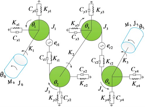
Due to the backlash caused by the flank clearance, the two gears that originally meshed with each other may not always remain engaged, especially when the system starts to run. Because the space between the gears exists, the first pinion must be turned over the angle corresponding to the lost motion before meshing with the large gear At this time, the meshing stiffness and are required to be corrected. The corrected meshing line stiffness are:
where – linear time-varying meshing stiffness of the -stage gear transmission, 1, 2; , – the angular displacement of gear 1 and gear 3; – backlash of the -stage gear transmission.
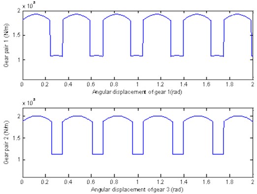
The meshing stiffness of the gear system is approximately parabolic by changing of meshing position. For the determined by the parameter gear pair, the theoretical position of meshing in, meshing out and the joint are fixed. Thus, the time-varying stiffness curve of gear pair 1 and gear pair 2 were obtained by the undetermined coefficient method, as illustrated in Fig. 2. Then the time-varying stiffness data can be substituted into the dynamics model.
Fig. 2Time – varying stiffness curve of gear pair 1 and gear pair 2
Regardless of the influence of tooth shape and pitch error and radial displacement of gear, considering the influence of backlash and time-varying meshing stiffness, the kinetic equations of torsional vibration of two-stage spur gear transmission system is established according to Newton’s second law and related dynamics knowledge, as shown in the following:
where – the base radius of each gear of the two - stage gear system, 1, 2, 3, 4; – the moment of inertia of the gears around the rotating shaft, 1, 2, 3, 4; , – the moment of inertia of the motor and load; , – motor input torque and the resistance torque of the load; – torsional stiffness of input shaft, intermediate shaft, output shaft, 1, 2, 3; – the damping coefficient of input shaft, countershaft and output shaft, 1, 2, 3; – the rotational angular displacement of input shaft, 4 gears and output shaft, 1, 2, 3, 4, 5; – the time – varying damping coefficient of gear pair , 1, 2.
3. Simulation and experiment
3.1. Adams kinematics simulation
For a precision-operated transmission system, the accuracy of the load section is of the utmost concern, so the analysis of the effect of the backlash on the gear system is mainly reflected in the load accuracy at the output shaft. Based on the ADAMS multi-body dynamics solver platform, a nonlinear dynamic model of the gear system considering the time-varying meshing stiffness, meshing damping, motor, load, transmission shaft torsional stiffness and bearing elastic support is established. To study the dynamic characteristics of the gear transmission system more realistically and comprehensively in the ADAMS platform, an improved flex-torsion coupling dynamics model of the gear transmission system is used here. To describe the time-varying mesh stiffness of a gear in ADAMS, an equivalent transformation of the model is required: the meshing relationship between the gear teeth is converted into a force and a couple acting on the centroid of the gear.
The collision parameters of the two-stage gear system are solved according to the parameters of the known gears and the like, as shown in Table 1.
Table 1Contact failure parameters of two-stage gear transmission gear in ADAMS
Symbol | Gear 1 | Gear 2 | Gear 3 | Gear 4 | |
Material | None | Stainless steel | Titanium alloy | Stainless steel | Titanium alloy |
Index circle radius | (mm) | 2.25 | 11.25 | 4.5 | 90 |
Elastic Modulus | (pa) | 2e11 | 1.1e11 | 2e11 | 1.1e11 |
Poisson's ratio | 0.27 | 0.33 | 0.27 | 0.33 | |
Stiffness coefficient | (N/m) | 4.7e9 | 7.11e9 | ||
Damping coefficient | (Ns/m) | 4.7e6 | 7.11e6 | ||
Collision index | 1.5 | 1.5 | |||
A 3D solid model of gears with a certain level of accuracy is built in SolidWorks and imported into ADAMS. The constraints are added to the model in ADAMS. As shown in Table 2, the gear mass, moment of inertia, torsional stiffness and damping of the shaft are set to obtain the constraint model, as shown in Fig. 3. The effects of the backlash on the start, normal operation and stop of the gear system are analyzed by simulating the angular velocity and output response of each gear.
3.2. Experiment and correctness verification of simulation model
To verify the correctness of the Adams model of the space-driven gear system, tests were carried out on an inertial load simulator. The three-dimensional model and the physical map of the experimental device are shown in Fig. 4.
Table 2Constraints of each unit in Adams
Ground | Motor | Gear 1 | Gear 2 | Gear 3 | Gear 4 | Load | |
Ground | – | Rotating pair | Rotating pair | Rotating pair | Rotating pair | Rotating pair | Fixed |
Motor | Rotating pair | – | Torsion spring 1 | – | – | – | – |
Gear 1 | Rotating pair | Torsion spring 1 | – | Contact 1 | – | – | – |
Gear 2 | Rotating pair | – | Contact 1 | – | Torsion spring 2 | – | – |
Gear 3 | Rotating pair | – | – | Torsion spring 2 | – | Contact 2 | – |
Gear 4 | Rotating pair | – | – | – | Contact 2 | – | Torsion spring 3 |
Load | Fixed | – | – | – | – | Torsion spring 3 | – |
Fig. 3Constraint model of two-stage gear system in Adams
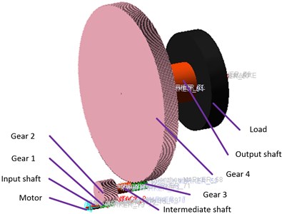
Fig. 43D model and physical map of the test device
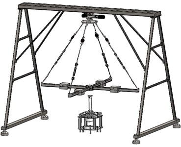
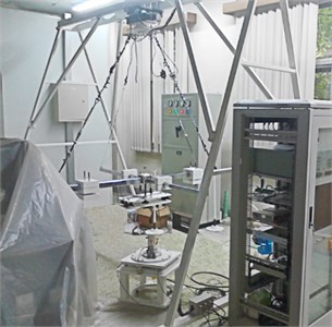
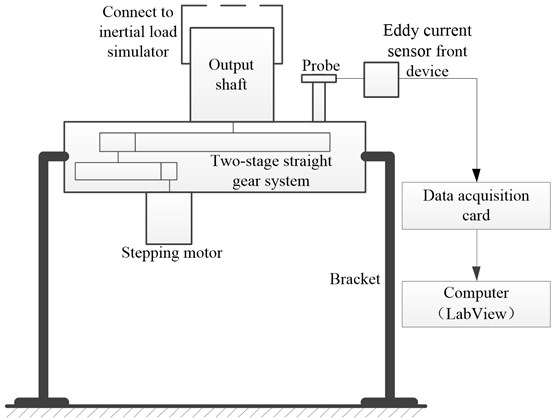
The experimental device and data acquisition system are shown in Fig. 5. The input shaft of the space drive gear system is connected to the stepper motor, and the output shaft is connected to the inertia load simulator. Two eddy current sensors are installed at the radial position of the output shaft to measure the eccentricity of the output shaft. The two eddy current displacement sensor are installed in each of the horizontal and vertical directions of the output shaft section, and the displacement sensor is composed of a probe, a preamplifier, and a signal line. In the static condition, the distance between the front end surface of each displacement sensor and the test surface is about 1 mm. Solving two derivatives with displacement sensor signal, the output shaft vibration acceleration signal can be obtained. The parameters of the two-stage gear drive system are presented in Table 3.
Table 3Two-stage gear drive system parameters
Gear pair 1 | Gear pair 2 | ||
Number of teeth of gear 1 | 18 | Number of teeth of gear 3 | 18 |
Number of teeth of gear 2 | 90 | Number of teeth of gear 4 | 360 |
Modulus of gear 1 | 0.25 mm | Modulus of gear 3 | 0.5 mm |
Modulus of gear 2 | 0.25 mm | Modulus of gear 4 | 0.5 mm |
Material of gear 1 | stainless steel | Material of gear 3 | stainless steel |
Material of gear 2 | Titanium alloy | Material of gear 4 | Titanium alloy |
Accuracy level | 6-h | Accuracy level | 6-h |
Tolerance of cycle accumulated deviations of gear 1 | 0.016 mm | Tolerance of cycle accumulated deviations of gear 3 | 0.016 mm |
Tolerance of cycle accumulated deviations of gear 2 | 0.02 mm | Tolerance of cycle accumulated deviations of gear 4 | 0.032 mm |
Tolerance of PE of gear 1 | 0.008 mm | Tolerance of PE of gear 3 | 0.008 mm |
Tolerance of PE of gear 2 | 0.008 mm | Tolerance of PE of gear 4 | 0.006 mm |
Fig. 5Test device and data acquisition system
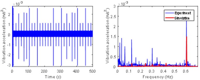
When the load inertia is the default value 25.8, according to the data measured by the eddy current displacement sensor, the time domain curve of the eccentricity of the output shaft is calculated, as shown in Fig. 8. The time domain curve of the data measured by the vibration acceleration sensor is shown in Fig. 9. The data is Fourier transformed to obtain the frequency domain curve, and compared with the frequency domain and the curve obtained by solving with Adams, as shown in Fig. 6 and Fig. 7.
From the frequency domain curves in Fig. 6 and Fig. 7, it can be seen that the experimental results are in good agreement with the results of the numerical solution. The frequency components are mainly concentrated on the frequency of the input shaft, intermediate shaft, and the meshing frequency of the two-stage gear pair and its frequency multiplier. There are still some frequency components that cannot be analyzed in the experimental results.
Fig. 6Time domain and frequency domain diagram of output shaft eccentricity
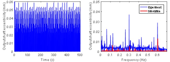
Fig. 7Time domain and frequency domain diagram of output shaft vibration acceleration
4. Backlash simulation analysis
4.1. Influence of backlash on the start-up time of the two-stage gear system
After adding the constraint, add a torque to the motor to simulate the starting torque of the motor. Set the simulation time 1 s, and the number of simulation steps 10000. The output angular velocity response of gear pair 1 after simulation is as shown in Fig. 8.
Fig. 8Output angular velocity response curve of gear pair 1
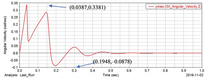
It can be seen from Fig. 3 that the output angular velocity of gear pair 1 is finally stabilized after several reciprocating oscillations, and reaches the first maximum 0.3381 rad/s at the time 0.0387 s, and reaches the negative maximum –0.0878 rad/s at the time 0.1948 s. The angular velocity has a negative value, indicating that gear 1 has reversed.
In the modeling, the backlash maximum values of gear pair 1and 2are 15.48 μm and 19.02 μm, respectively.
According to the known parameters of the gear, the pitch circle radius of gear 1:
The maximum backlash value is 15.48 μm, and the arc angle occupied by the arc of the index circle is:
In Fig. 3, the gear 1 passes through 0.0387 s to reach the maximum speed 0.3381 rad/s, and at this time, the angle at which the gear 1 rotates is:
Comparing the two angles, we can find that the two angles are not much different. Excluding the accuracy of the Adams simulation calculation and the error of the contact depth of the set, the two angles are approximately equal, which means that is indeed the time it takes for gear 1 to turn over the backlash.
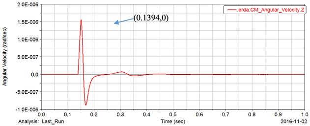
Fig. 9 and Fig. 10 are output angular velocity response curves of the gear 2 and the gear 4. The gear 2 and the gear 4 do not start to rotate instantaneously with the start of the motor, and there is a time lag with respect to the gear 1 and the motor due to the existence of the backlash. Each gear pair has a backlash, and the front gear must rotate a certain angle before meshing with the rear gear to drive the rear gear to rotate and finally output to the load.
Fig. 9The output angular velocity response curve of gear 2
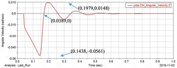
Fig. 10Output angular velocity response curve of gear 4
It can be seen from Fig. 3 that the gear 2 starts to rotate at 0.0389 s and reaches the maximum value of the speed at 0.1438 s (the gear 2 and the gear 1 rotate in opposite directions, so the angular velocity is negative). Here, the time point at which the gear 2 starts to rotate is exactly the time point when the gear 1 idling reaches the maximum speed, and the time to reach the maximum speed is also the time point at which the gear 4 starts to rotate. It should be noted that the time 0.0387 s in Fig. 2 and the 0.0389 s in Fig. 4 are not completely identical. This is due to the effect of setting the contact force during the ADAMS simulation. After a certain contact depth is set, the contact force acts, the time in the two figures is approximate the same time. The time points in other figures are the similar.
4.2. Influence of backlash on normal operation of two-stage gear transmission system
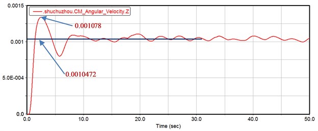
The constraint between load and ground in Table 1 above is changed to rotary pair, and the friction at each rotary sub-position is added. The simulation time is set to 50 s and the number of simulation steps is set to 10,000 steps. Set the input angular velocity of the motor to 0.10472 rad/s. The response curve at the load position is shown in Fig. 11. It can be seen that the load will still fluctuate around the average angular velocity 0.10472 rad/s after running for a certain period of time. The maximum fluctuation amplitude reaches 0.001078 rad/s, which exceeds the average 2.94 %.
Fig. 11Angular velocity response curve of the output load
4.3. Influence of backlash on the stoppage of two-stage gear transmission system
The influence of the backlash on the start-up and normal smooth operation of the two-stage gear transmission is analyzed in the previous section. The following is an analysis of the influence of the motor on the braking. First, the motor’s drive function is modified to step(time,0,0,0.01,0.10472)+step(time,35,0,35.01,–0.10472), and let the motor reach the required angular velocity 0.10472 rad/s quickly in the initial time 0-0.01 s. Then the motor maintains the constant input speed during the time 0.01~35 s. Finally brakes at 35 s and the system speed drops to zero. Keeping other constraints unchanged, the simulation is performed again. The simulated output angular velocity response curve is shown in Fig. 12. The point A: (35, 0.001047) indicates the time point at which the braking starts, and the point B: (39.755, –8.76e-4) indicates the maximum reverse angular velocity point of the load after the motor is braked. This is because when the gear system of the current surface decelerates, the rotational inertia of the load is large, and the load continues to rotate due to the inertia, but the speed is reduced due to the torsional resistance torque of the output shaft. When the speed drops to 0, the torsional resistance torque of output shaft reached the maximum, and the load will start to reverse in rotation due to the torque, and reach the reverse maximum speed point at time 39.755 s. It can be simply calculated that the load reaches the negative maximum at the elapsed time 4.755 s, and then the velocity decays to zero after several cycles of reciprocating oscillation.
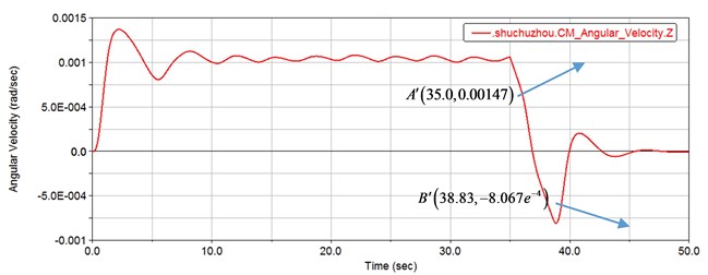
To investigate the effects of the backlash, the gear pair model without backlash was established again and all simulation settings were consistent with the simulation settings with backlash above. Fig. 13 shows the load simulation curve after the simulation of the gear set without backlash. It can be seen from the figure that the load reaches a negative maximum at time 38.83 s after braking at point , and the elapsed time is 3.83 s. Compared to the gear set with backlash, the load takes less time, which is mainly because the gear has a backlash, and the load needs to pass through the backlash before it can mesh with other gears.
Fig. 12The angular velocity response curve of the gear set with backlash under braking
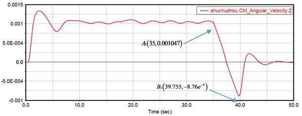
Fig. 13Angular velocity response curve of gear set with no backlash
5. Influence of different factors on the dynamic response of gear system
The large inertia load is taken into account in the dynamic model to simulate and control the motor of the drive mechanism. The gear system quickly reach the required angular velocity in a short time, and maintain a constant speed for a certain period of time. When the brake is applied at 35s, the motor speed is quickly reduced to 0, and the load angular velocity response curve is shown in the red curve of Fig. 9. In order to study the influence of large inertia loads on the dynamic response of the drive mechanism, the load inertia was reduced to one-tenth of the original and the load angular velocity response curve was obtained, as shown in the blue curve of Fig. 14.
Fig. 14Comparison of dynamic response under different load inertia
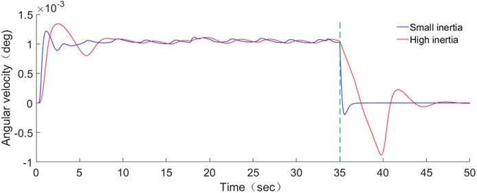
From Fig. 14, it can be seen that when the motor start and brake, the load angular velocity response of the drive mechanism under large inertia loads has a significant inertial hysteresis relative to small inertial loads, which is caused by the time-lag effect of large inertia loads. Large inertia loads cause the system to respond slowly, and the dynamic characteristics of each axis are inconsistent, which inevitably causes the TE of the system. When the motor start and brake, the load angular velocity response of the drive mechanism under large inertia loads fluctuates obviously relative to a small inertia load. At this time, the drive mechanism generates large vibration, which results in poor system stability and seriously affects the service life of the drive mechanism. In normal operation, compared with small inertia loads, the angular velocity response of the large inertia load drive mechanism is less frequent, and the operation is more stable. This is because the large inertia load helps to absorb disturbances during operation and has strong anti-disturbance capability. By contrast, it is found that there is a big difference between the dynamic response of the gear system under large inertia load and small inertia load. Therefore, when studying the two-stage straight gear system of space drive mechanism, large inertia load should be taken into account. It is of great significance to study large inertia loads. In the subsequent experimental studies, the transmission errors under different load inertias were analyzed.
5.1. Influence of shaft stiffness and damping on dynamic response of gear system
To study the influence of the three internal axes of gear system, the stiffness and damping of the input shaft, the intermediate shaft and the output shaft of the system are respectively modified. Respectively, the stiffness and damping are modified to 50 % and 150 % of the default value to simulate the response of the shaft stiffness to the system under material or diameter changing.
Fig. 15Load response curve for different input, intermediate and output shaft stiffnesses
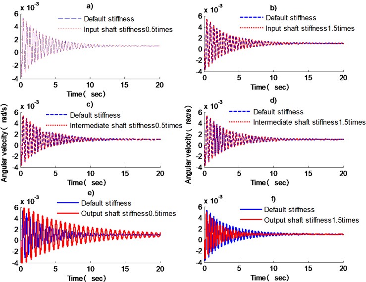
Modify the model in ADAMS, remove the constraints at the motor, and add angular velocity to the system. The input angular velocity is set to 0.10427 rad/s, and a reverse resistance torque –1 N⋅m is added to the load. Fig. 15 is the corresponding curve of the load angular velocity under the input shaft, intermediate shaft and output shaft stiffness changing. In the figure, a) and b), c) and d), e) and f) are the comparison of the input shaft, intermediate shaft and output shaft.
It can be seen from the figure that for the two-stage gear reduction system, the input shaft and the intermediate shaft have little effect on the load response under the condition of changing the stiffness, while the angular velocity of the load when the output shaft stiffness changed can be clearly seen. As the output shaft stiffness increases, the apparent response speeds up. As in the case of e), the stiffness of the output shaft is 50 % of the default stiffness, the angular velocity of the load is 0.002339 rad/s at time 10.33 s, while the angular velocity of the load in the f) diagram is only 0.001048 rad/s, which has basically reached the smooth working angular velocity of the system.
5.2. The influence of gear materials on the dynamic response of the system
The influence of the gear input shaft, intermediate shaft and output shaft on the vibration system is analyzed in the previous section. The meshing stiffness of the gear is analyzed below. In the ADAMS virtual prototype, the transmission of the gear mainly uses the contact collision between the teeth, and the decisive action is the collision contact stiffness between the teeth.
For gears to set the collision contact between the teeth, the stiffness coefficient can be determined according to the following formula:
Changing the material of the gear can change the impact contact stiffness of the gear without changing the gear ratio and overall geometry of the gear. The gear pair stiffness and damping under different materials are calculated by changing the material of the gear pair respectively. The collision contact stiffness of the gear pair is calculated by Eq. (12), and the damping is taken 0.1 %-1 % of the stiffness according to the empirical value. Table 4 shows the stiffness values of the gear pairs of 7 different materials. In the default state, the materials of the first and second gear pairs are stainless steel/titanium alloy.
Table 4Impact stiffness and damping of gear pairs under different materials
Serial number | 1 | 2 | 3 | 4 | 5 | 6 | 7 |
Gear pair 1 | Default | Stainless steel / stainless steel | Titanium alloy/titanium alloy | Default | Default | Stainless steel / stainless steel | Titanium alloy/titanium alloy |
Stiffness value (N/m) | 4.7×10⁹ | 6.38×10⁹ | 3.73×10⁹ | 4.7×10⁹ | 4.7×10⁹ | 6.38×10⁹ | 3.73×10⁹ |
Gear pair 2 | Default | Default | Default | Stainless steel / stainless steel | Titanium alloy/titanium alloy | Stainless steel / stainless steel | Titanium alloy/titanium alloy |
Stiffness value (N/m) | 7.11×10⁹ | 7.11×10⁹ | 7.11×10⁹ | 9.65×10⁹ | 5.63×10⁹ | 9.65×10⁹ | 5.63×10⁹ |
Fig. 16 shows the load response curve of the meshing impact position of the 7 sets of different material gear pairs. The impact of the gear drive can be clearly seen from the figure. The combination of the gear pairs of different materials has a great influence on the system.
The fluctuation values of the seven combinations in Fig. 16 are listed in Table 5. It can be seen from the figure and the table that when the second-stage gear pair uses stainless steel, regardless of whether the first-stage gear uses stainless steel or not, the response amplitude of the load is relatively large. When the second-stage gear pair uses titanium alloy (combination 5, 7), the impact amplitude of the system is lower, which reduces the 22.73 % and 21.82 %, respectively, from the default combined shock fluctuations.
When the second-stage gear is made of stainless steel (combination 4, 6), especially when the two-stage gear pair is all made of stainless steel (combination 6), the shock vibration is the largest, and the fluctuation range is beyond the default combination. Therefore, to reduce the impact of the load on the gear system, it is recommended to use titanium alloy materials.
Fig. 16Partial enlarged view of the load response curve of different material gear pair combinations
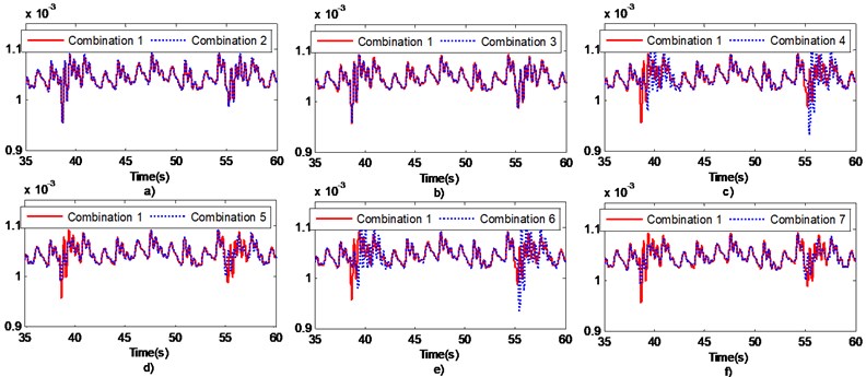
Table 5Load angular velocity fluctuations at different combinations
Combinations | Minimum value of fluctuation | Maximum value of fluctuation | Amount of fluctuation | Percentage of fluctuation |
1 | 0.0009883 | 0.001095 | 0.00011 | – |
2 | 0.0009879 | 0.001098 | 0.00011 | 0 |
3 | 0.0009883 | 0.001093 | 0.0001 | –9.1 % |
4 | 0.0009262 | 0.001129 | 0.0002 | 81.81 % |
5 | 0.001004 | 0.001092 | 0.000085 | –22.73 % |
6 | 0.0009294 | 0.001125 | 0.0002 | 81.81 % |
7 | 0.001003 | 0.001089 | 0.000086 | –21.82 % |
6. Conclusions
1) A nonlinear dynamic model of 8-degree-of-freedom two-stage spur gear is established, and the effects of backlash and time-varying stiffness are considered. It is pronounced that compared to the small inertia load system, the load angular velocity response of the drive mechanism under the large inertia load has significant hysteresis.
2) The influence of the backlash on the starting, normal operation and stop of the gear system is analyzed by ADAMS. The stiffness and damping of the shaft and the load response curve under the condition of the gear material are analyzed. The simulation curve shows that the output shaft has a great influence on the system. When the stiffness of the shaft is increased by 0.5 times, the torsional vibration response curve will be obviously decayed rapidly. For the gear pair, the use of titanium alloy material can greatly reduce the amplitude of the stiffness fluctuation at the time of meshing, which is conducive to gear transmission accuracy.
3) This paper enriches the research on the nonlinear model of the two-stage spur gear and the large inertia load, which provides an important reference for the actual design of the gear system. For the time-varying and nonlinear perturbation problems generated by the large inertia load space drive mechanism, a theoretical reference is provided, and the optimization direction of the gear rotation disturbance is pointed out.
7. Data availability
The data used to support the findings of this study are available from the corresponding author upon request.
References
-
Wang Lisheng Calculation and simulation of torsional vibration resonance frequency of antenna mount drive system. Modern Electronic Technology, Vol. 8, 2005, p. 115-117.
-
Yu L., Wang G., Zou S. The experimental research on gear eccentricity error of backlash-compensation gear device based on transmission error. International Journal of Precision Engineering and Manufacturing, Vol. 19, Issue 1, 2018, p. 5-12.
-
Chen Q., Ma Y., Huang S., et al. Research on gears’ dynamic performance influenced by gear backlash based on fractal theory. Applied Surface Science, Vol. 313, 2014, p. 325-332.
-
Kahraman A., Singh R. Interactions between time-varying mesh stiffness and clearance non-linearities in a geared system. Journal of Sound and Vibration, Vol. 146, Issue 1, 1991, p. 135-156.
-
Cao X., Deng X., Wei B. A novel method for gear tooth contact analysis and experimental validation. Mechanism and Machine Theory, Vol. 126, 2018, p. 1-13.
-
Chao L., Zongde F., Feng W. An improved model for dynamic analysis of a double-helical gear reduction unit by hybrid user-defined elements: experimental and numerical validation. Mechanism and Machine Theory, Vol. 127, 2018, p. 96-111.
-
Wang Y., Liu C., Liao Y. Electromechanical dynamic simulation and experiment for multi-stage gear transmission system with planetary gears. Cluster Computing, Vol. 22, Issue 2, 2019, p. 3031-3041.
-
Cai Y. Simulation on the Rotational Vibration of Helical Gears in Consideration of the Tooth Separation Phenomenon (A New Stiffness Function of Helical Involute Tooth Pair). The Joseph Purcell Research Memorial, 1930.
-
Litak G., Friswell M. I. Vibration in gear systems. Chaos Solitons and Fractals, Vol. 16, Issue 5, 2003, p. 795-800.
-
Sawalhi N., Randall R. B. Simulating gear and bearing interactions in the presence of faults: Part I. The combined gear bearing dynamic model and the simulation of localised bearing faults. Mechanical Systems and Signal Processing, Vol. 22, Issue 22, 2008, p. 1924-1951.
-
Shen Y., Yang S., Liu X. Nonlinear dynamics of a spur gear pair with time-varying stiffness and backlash based on incremental harmonic balance method. International Journal of Mechanical Sciences, Vol. 48, Issue 11, 2006, p. 1256-1263.
-
Comparin R. J., Singh R. Frequency response characteristics of a multi-degree-of-freedom system with clearances. Journal of Sound and Vibration, Vol. 142, Issue 1, 1990, p. 101-124.
-
Walha L., Fakhfakh T., Haddar M. Nonlinear dynamics of a two-stage gear system with mesh stiffness fluctuation, bearing flexibility and backlash. Mechanism and Machine Theory, Vol. 44, Issue 5, 2009, p. 1058-1069.
-
Dhatt G., Touzot G., Lefrançois E. Finite Element Method. Springer, Vol. 2, Issue 1, 2012, p. 7-14.
-
Yang T., Yan S., Han Z. Nonlinear model of space manipulator joint considering time-variant stiffness and backlash. Journal of Sound and Vibration, Vol. 341, 2015, p. 246-259.
-
Xu Z. Load equivalent simulation method of ultra-large moment of inertia of space station redocking manipulator. Journal of Information and Computational Science, Vol. 12, Issue 2, 2015, p. 431-441.
-
Chen S., Zhao J., Li B., et al. Nonlinear dynamic model and governing equations of low speed and high load planetary gear train with respect to friction. International Conference on Consumer Electronics, Communications and Networks, 2011.
-
Hammami A., Rincon A. F. D., Chaari F., et al. Effects of variable loading conditions on the dynamic behaviour of planetary gear with power recirculation. Measurement, Vol. 94, 2016, p. 306-315.
About this article

This work was supported by the Municipal Education Commission project of Beijing (JC001011201601).
