Abstract
In the design process of traditional ship shafting, the design quality is generally hard to get guaranteed for the lack of discipline coupling. In this paper, Multidisciplinary Design Optimization (MDO) is innovatively introduced to ensure design quality. Multidisciplinary decomposition of shafting can help to construct the MDO model of ship shafting based on multidisciplinary feasibility method. Then the sub-discipline model of shifting design can be further established, including calibration neutron discipline model, whirling vibration model, and dynamic stiffness of radial oil film bearing model. Collaborative operation is implemented by the multidisciplinary model of shifting to obtain the experimental results. Based on Radial Basis Function (RBF) neural network, the responsive surfaces of variable, bearing load, and support stiffness can be constructed, in the meanwhile the dynamic stiffness decoupling of vibration model can be obtained. Fireworks algorithm is used to establish multidisciplinary optimization of seven-dimensional design variable. The results show that MDO helps improve the quality of shafting alignment and whirling vibration. The work in present paper also provides insight for the future optimization of research methods, design quality, and engineering experiments.
Highlights
- Multidisciplinary Design Optimization (MDO) is innovatively introduced to ensure design quality of ship shafting.
- Under MDO framework, the sub-discipline model of shifting design is established, including calibration neutron discipline model, whirling vibration model, and dynamic stiffness of radial oil film bearing model.
- Based on Radial Basis Function (RBF) neural network, the responsive surfaces of variable, bearing load, and support stiffness can be constructed, in the meanwhile the dynamic stiffness decoupling of vibration model can be obtained.
- Fireworks algorithm is used to establish multidisciplinary optimization of seven-dimensional design variable.
1. Introduction
Shafting is an important part of the power plant, which transfers power from the main engine to the propeller contributing to the ship movement [1]. Shafting alignment quality and vibration characteristics are two significant indexes related to the overall quality of modern ship shafting. Poor alignment will lead to various shaft safety problem, such as excessive vibration, excessive bearing temperature, abnormal bearing abrasion and even shaft fracture or crankshaft deformation, which will seriously affect the reliability, safety and vitality of ships. The whirling vibration of shafting is jointly produced by transverse propeller excitation force, main engine excitation force, unbalance inertia force of rotor and misaligned excitation. Excessive whirling vibration will cause shaft resonance and abnormal abrasion of stern bearing, accordingly, the support characteristics and shifting alignment quality will be negatively influenced, as a result, the ship stealth and safety would be highly affected [1, 2].
With the development of large and high-speed modern ships, factors such as main engine power increase, stern stiffness decrease, and shafting speed increase under electric propulsion would cause the increasing exciting force and the decreasing natural shafting frequency, so the cyclotron response is getting notable in calculation. A review of literature [2-4] reveals that, attention has increasingly been paid on joint analysis of shifting alignment and vibration. As for the research methods, traditional research ideas in this field mainly follows the sequence of calculating the alignment firstly and then analyzing the vibration. For example, Dong et al. [3] proposed the concept about alignment of shafting curves, where the lumped and distributed parameter element hybrid shafting model is established. They also discussed the influence of propeller thrust, axis inclination, bearing span and stern bearing displacement on the alignment. In addition, they concluded that the deflection of shafting is not the main cause of whirling vibration according to the calculation. Zhou et al. [4] used three bending moments to calculate the alignment, and analyze the influence of hull deformation, stern bearing fulcrum position and oil film stiffness on reasonable alignment, so that the integrated analysis software of shafting vibration and alignment would be developed.
From a dynamic perspective, coupling factors of shaft alignment and whirling vibration characteristics mainly include: vertical and axial bearing displacement, bearing stiffness, number of shafting support points, propeller excitation, main engine excitation, structural parameters of shafting etc. [5-8]. Murawski and Ostachowicz [9] firstly conduct the static shaft alignment of main engine under cold and hot state, where he considered the stiffness and damping of ship base, bearing stiffness, oil lubrication bearing film characteristics and other factors, based on the multi-fulcrum shaft system alignment model established for stern bearing, was implemented. Then the whirling vibration response was calculated after alignment. It was remarkable that the bearing support characteristics had a significant impact on the transmission of whirling vibration. Lin [10] discussed shafting in fitting the parallel misalignment, the establishment of the shaft system under the state of whirling vibration calculation mathematical model, through the analysis, they found that the influence of the amount of monitoring stations in response to the amplitude increases with the speed. Fang [11] used the Finite Element Method (FEM) to qualitatively analyze the influence of the misalignment parameters of the flange and clutch on the vibration characteristics of the shaft system. They found that the misalignment of the flange and clutch has limited influence on the whirling vibration of the shaft system in linear alignment. Lai et al. [12] pointed out that the bearing stiffness can be regarded as a design variable based on the theory of rotor dynamics and sliding bearing lubrication, the alignment characteristics and whirling vibration response of shafting under linear alignment and reasonable alignment were calculated numerically. They used the linear programming to complete the comprehensive optimization of shaft alignment and whirling vibration.
In general, shafting response is a complicated process, involving rotor dynamics, fluid mechanics, friction mechanics, structural mechanics and many other disciplines, which are high complex and closely coupled. Therefore, it is hard to establish an accurate model even with high cost [13-17]. The main problems of existing shafting design methods could be concluded: (1) Due to the lack of comprehensive consideration of the various disciplinary factors involved in shaft alignment and vibration, the problem of decoupling of inter-disciplinary coupling variables cannot be solved effectively. (2) The existing design method mainly focuses on single factor optimization design, and the target of shafting optimization is not closely combined with the general requirements of Marine power plant [18]. This article introduces multidisciplinary design optimization method from the perspective of shaft system optimization design, where the main idea is to give full consideration of the coupling of sub-discipline variables in the process of complex system design. MDO is a method to solve structural design problems of complex systems. Although few application research studies in shafting design can be found, it has been successfully applied in aerospace, missile design and other fields due toits advantages in multidisciplinary coupling design. By using the MDO method, the model of sub-discipline was established to be accurate or approximate, and the optimization rules of system level and technology were established based on the optimization strategy, in addition, the optimization design was completed by using intelligent optimization algorithm.
The feasibility has been successfully applied in the field of underwater vehicle, aircraft and missile design [19-22]. For example, the US has successfully used MDO to optimize the design of DD-21 ship structure parameters. Yukishm [23] proposed the design scheme of container ship based on MDO. Pan [24] integrated GGX design module in Isight environment, combining Finite Element Analysis with MDO, and completed the structural optimization of the whole ship with more than 200 units.
In this paper, the optimization goal is to comprehensively improve the quality of shaft alignment and the characteristics of whirling vibration. The multidisciplinary model and self-disciplinary model of shaft alignment are established to complete the variable decoupling of shaft alignment and vibration state. The multidisciplinary optimization design of shaft alignment is implemented by using fireworks algorithm.
2. Multidisciplinary optimal design model for shafting
The main factors affecting shafting alignment include: (1) shafting arrangement, especially bearing number and span; (2) dynamic stiffness of supporting oil film; (3) diagonal angle of stern bearing and (4) body weight of shafting.
The main factors affecting the whirling vibration characteristics include: (1) modeling mode and position of fulcrum of support bearing; (2) dynamic characteristics of support bearings, involving stiffness, damping, friction and wear; (3) shafting alignment, including bearing position, alignment and (4) propeller hydrodynamic effect, especially propeller transverse excitation force.
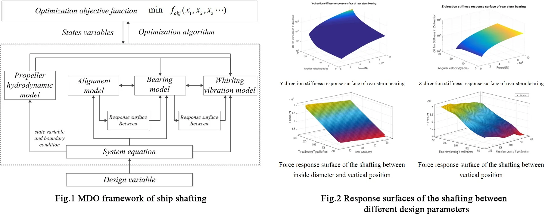
Based on the above analysis, each factor is mapped to sub-disciplines such as structure size, shafting arrangement, supporting characteristics and propeller performance, etc. The multi-disciplinary decomposition is carried out with the optimization objectives of alignment quality and whirling vibration characteristics to obtain the multidisciplinary design structure matrix of shafting, as shown in Fig. 1.
Fig. 1Structure matrix of the ship shafting
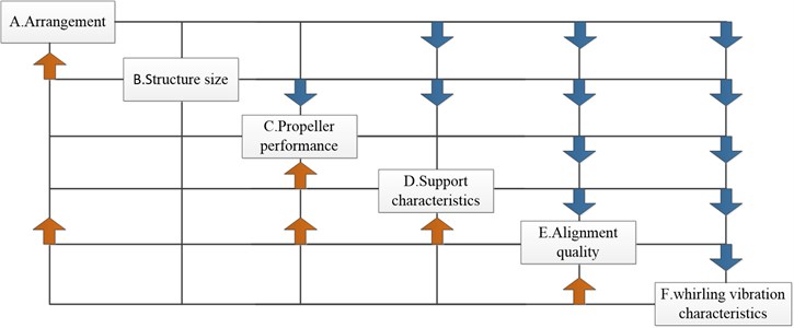
The structure matrix reflects the coupling degree and direction among different disciplines. Shafting arrangement and structure size are unidirectional coupling with other disciplines, which should be considered as design variables. The propeller performance, support characteristics, alignment quality and whirling vibration characteristics are bidirectionally strong coupling among them, which are modeled, analyzed and decoupled separately. Based on the above analysis, the multidisciplinary feasible method (MDF) is selected as the overall optimization strategy to further give the multidisciplinary design optimization. The framework is shown in Fig. 2.
In Fig. 4, design variables , and are input to the system and sub-disciplinary model, assigned by design system equations. The optimization objective is a polynomial composed of the state variables and the whirling vibration state. The optimization results are controlled by the weight coefficients of the variables.
The hydrodynamic forces of propeller calculated by the quasi-steady method were input into the calculation model of whirling vibration. The coupling state variables of the alignment calculation model were mainly bearing load , and the coupling parameters of the bearing support model. The calculation model of whirling vibration were mainly rotation speed and dynamic stiffness .
In order to accelerate the optimization process and improve the convergence, the experimental design was carried out based on the accurate model calculation results. The response surface of bearing support model was established to complete the alignment and the whirling vibration decoupling. The system-level mathematical model is:
Fig. 2Shaft multidisciplinary design optimization framework
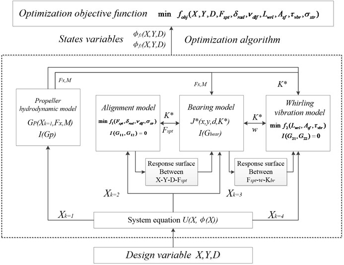
The sub-disciplines model of alignment is:
Whirling Vibration Sub-discipline is:
where, , , , are the state variables for alignment calculation, representing bearing support reaction force, shaft segment rotation angle, shaft deflection and stress respectively; , , are the state variables of whirling vibration calculation, representing the amplitude, shaft segment safety factor and critical speed of each order in the vibration monitoring point respectively; , , are the state variables for bearing support model, representing oil film thickness, bearing stiffness, bearing damping respectively; is inequality constraints; is equality constraints; and is response surface consistency constraints.
3. Sub-disciplinary model of shafting design
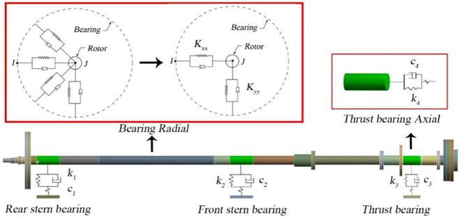
As shown in Fig. 3, the shafting is composed of propeller, rear stern bearing, tail shaft, front stern bearing, intermediate shaft, universal coupling, thrust shaft, thrust bearing, elastic coupling and propulsion motor. The output end of the propulsion motor and input end of the shaft are connected by elastic coupling. The thrust shaft and the intermediate shaft are connected by universal coupling. The tail shaft is lubricated by radial sliding water-lubricated bearing and the thrust bearing is Michel oil lubricated bearings.
Fig. 3Shafting layout diagram
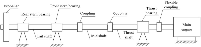
Table 1Main technical parameters of shafting
Variable | Symbol | Unit | Value |
Density | Kg/m3 | 7850 | |
Young’s modulus | N/m3 | 2.1×10¹¹ | |
Shear modulus | N/m3 | 7.6×10¹⁰ | |
Water supply coefficient | – | 1.14 | |
Outer diameter of tail shaft | mm | 310 | |
Inner diameter of tail shaft | mm | 160 | |
Outer diameter of mid shaft | mm | 312 | |
Inner diameter of mid shaft | mm | 200 | |
Length of rear stern bearing | mm | 2.01×10³ | |
Rear stern bearing allowable load | kN | 179.21 | |
Length of front stern bearing | mm | 2.51×10³ | |
Front stern bearing allowable load | kN | 152.83 | |
Length of thrust bearing | mm | 1.57×10³ | |
Thrust bearing allowable load | kN | 283.43 |
Considering both calculation accuracy and solution speed, the shafting modeling is simplified as follows:
(1) For each shaft segment, the properties of density, modulus and stiffness are uniformly distributed along the circular shafts with equal diameter, and no defect is considered in the material. In the process of propeller vibration and calculation, the propeller force is calculated by empirical formula, and the shaft system is input from the end of the shafting.
(2) The shafting is simplified to uniform equi-straight stepped shaft, ignoring the section changes of flange, coupling and shaft section.
(3) The radial stiffness of each bearing is simplified into two components: and . The support stiffness in each direction is considered as the series value of oil film stiffness and static stiffness of the base. The longitudinal stiffness of thrust bearing is simplified to the lumped mass-spring model.
(4) The fulcrum position of the rear stern bearing shall be located at 1/3 of the length of the bearing, and the fulcrum position of the front stern bearing and thrust bearing shall lie in the midpoint of the bearing.
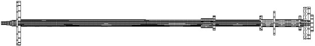
The simplified rear shafting model is shown in Fig. 4.
Fig. 4Shafting simplification diagram
3.1. Whirling vibration sub-disciplinary model
The rotor dynamics equation of propeller propulsion shafting is:
where, [] is the mass matrix, considering the water-attached mass of propeller, [] is the damping matrix, [] is the stiffness matrix, {} is the force acting on the shafting, and [] is the gyro effect matrix. When {} is a zero matrix, the eigenvalue of the homogeneous equation system is the natural frequency of the shafting and the solution is the free vibration response. The forced vibration response of shafting can be calculated by applying the approximate propeller force {}.
Based on the simplification and analysis above, the corresponding finite element model of shafting is established on Ansys platform, as shown in Fig. 5. Beam188 is used to establish the Axial section and Combin14 is used to establish the support spring system. Bearing 214 is adopted to represent the longitudinal spring element at thrust bearing. The elastic modulus of shafting material , 210 GPa, Poisson’s ratio , and density is 210 GPa. 0.32 and 7850 kg/m3 respectively. The buoyancy coefficient of the immersion section is –1000 kg/m3.
Fig. 5Shafting finite element model
The external input of whirling vibration calculation is propeller bearing force. According to the theory of propeller lifting line, the propeller is divided into segments along the radial direction. When the blade angle is , the thrust , torque and tangential force of the blade can be expressed as:
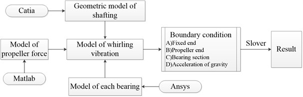
where, is radial position of segment , is the number of segments in radial direction, is the number of propeller blades. The amplitude of propeller bearing force at each rotation speed was obtained by quasi-steady calculation and applied to the shafting. According to instruction of shafting components and shafting structural parameters in Table 1, the shafting geometry model was established based on CATIA platform. The approximate calculation of propeller thrust and radial force was carried out in MATLAB. The calculation process of cyclotron vibration is shown in Fig. 6. Each bearing model is considered as a spring with vertical and lateral stiffness. Fixed restraint is imposed at the thrust bearing end, welding constraints are imposed on the thrust bearing end, and spring restraint is applied at the bearing. By applying the calculation force at the propeller end, the whirling vibration was calculated by the harmonic vibration module. Considering the vibration characteristics of the long shaft system, all analyzes are implemented within 0-200 Hz.
Fig. 6Simulation flow of whirling vibration
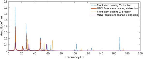
The whirling vibration response of each bearing monitoring point under initial state is obtained from the numerical results of shafting vibration model, as shown in Fig. 7.
Fig. 7Bearing amplitude-frequency characteristics of whirling vibration at initial state
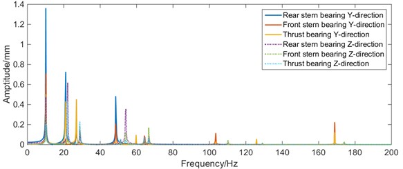
It can be seen from Fig. 7 that, in the range of 0-60 Hz, the amplitude of whirling vibration of the rear stern bearing is much higher than that of the front stern bearing and thrust bearing, and the amplitude of direction is higher than that of direction. Therefore, great priority should be given to the improvement of whirling vibration characteristics of the stern bearing in the optimization process.
3.2. Alignment sub-discipline model
Each shaft segment is discretized into a combination of elastic beam elements in the alignment calculation, for the shafting is considered as a multi-support continuous beam with equal cross-section, ignoring the radius change of the shaft section. Each beam element consists of two nodes to connect adjacent elements.
Fig. 8Stress analysis diagram of beam element
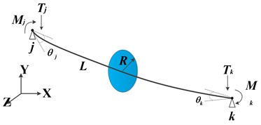
According to the relevant theory of material mechanics, for any element a, as shown in Fig. 8, and is the node in the left and right end surfaces of the element respectively, and then the displacement and force of the element can be expressed as:
where, , , , represent the linear displacement and angular displacement of the node in the direction of y-axis deflection, respectively; , , , represent the shear force and bending moment of the node and , respectively; and is the element stiffness matrix:
where, is the influence coefficient of shear deformation, and are shear modulus of elasticity; then, the relationship between shafting force and deformation can be obtained, where is the stiffness matrix of shafting, which can be obtained by combining . After obtaining the stiffness matrix, the actual geometric parameters of shafting and the support stiffness can be calculated. The alignment analysis of the shafting in the initial state (linear alignment) is carried out. The calculation results are shown in Fig. 9.
From Fig. 9, it can be seen that the shafting stern shaft deflection is the largest, with the maximum value of 0.479 mm. The maximum stress occurs at the cross-section change part of the stern shaft, with the maximum value of 15.93 MPa. The rear stern bearing load (62.19 kN) is higher than the front stern bearing load (18.25 kN) and the thrust bearing load (25.12 kN). It shows that the load and vibration characteristics of the rear stern bearing are poor, which should be given priority in the optimization process.
Fig. 9Calibration results of shafting alignment in initial state
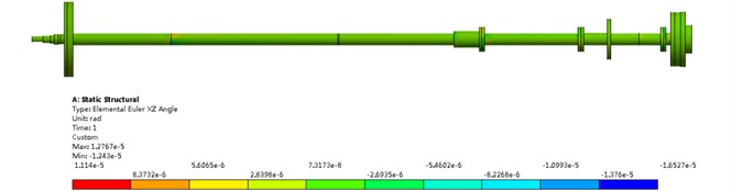
a) Rotation angle
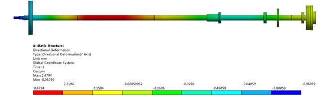
b) Deflection
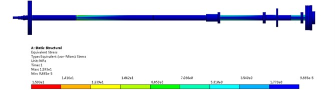
c) Equivalent stress
3.3. Sub-disciplinary model of bearing oil film stiffness
Bearing support stiffness is an important parameter in shafting alignment calculation and vibration calculation. It can be expressed as series values of static stiffness and oil film dynamic stiffness [25]:
where, is total equivalent stiffness at bearing, is stiffness of basic structure, is stiffness of oil film. Ship shafting usually operates at low speed and heavy load. Based on hydrodynamic lubrication theory, the Reynolds equation can be used to approximate the dynamic characteristics of oil film. The working principle of radial lubrication bearing in ship shafting is shown in Fig. 10.
The oil film distributes in the gap between the rotor and the bearing bush when the rotor runs in the bearing. The oil film fluid can be considered as the laminar flow applicable to the Reynolds equation, so the liquid film equation between the shaft diameter and the shaft bush is:
Assuming that the oil film pressure at the bearing boundary is 0 and the shaft section has noinclination inside the bearing, the radial force and tangential force of the bearing under stable operation can be expressed as follows:
where, is the bearing radius, is the shaft speed, is the lubricant oil viscosity coefficient, is the bearing length, is the average radial clearance inside the bearing, is the bearing eccentricity.
The resultant force could be calculated from the radial force and tangential force of oil film acts on the bearing through the bearing bush, which can be expressed as:
The load of the shafting can be obtained by the calibration calculation model established above. The magnitude and direction of the load are the same as that of numerically. Further derivation can obtain the expressions of bearing eccentricity ɛ and force attitude angle :
where, is modified Sommerfeld number. From Eq. (13), the remaining parameters can be approximately solved according to any two parameters of load, rotation speed and eccentricity. In order to simplify the calculation and construct a stiffness model of oil film support suitable for multidisciplinary optimization design, the bearing stiffness is simplified to a linear spring in both horizontal and vertical directions, and the stiffness matrix of oil film can be approximately expressed as follows:
The lateral stiffness and the vertical stiffness can be expressed as:
where is the approximate value of oil film thickness.
3.4. Decoupling approximate response analysis of design parameters
The coordinated operation of the shafting model requires high calculation costs. In order to accelerate the optimization speed, uniform design is adopted for the design variables. Taking the calculation results of each sub-model as sample points, the radial basis function neural network is used to generate the target response surface. Neural network has been widely used in many fields for its advantage of cost saving [26]. In present study, 5000 initial sample points are generated in the design variable space for training and verification. The load-design variable response surface of rear stern bearing is obtained as shown in Fig. 11.
Fig. 11Force response surface of rear stern bearing
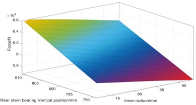
a) Force response surface of and
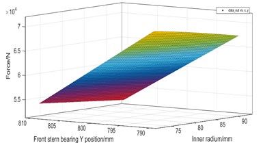
b) Force response surface of and
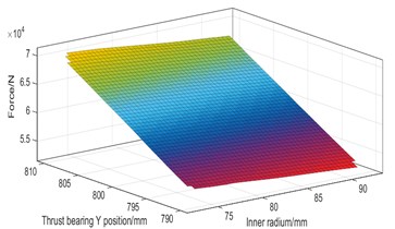
c) Force response surface of and
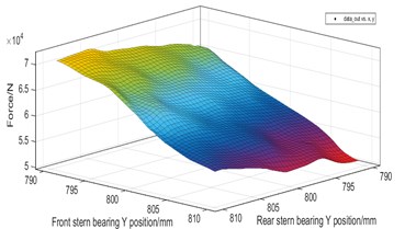
d) Force response surface of and
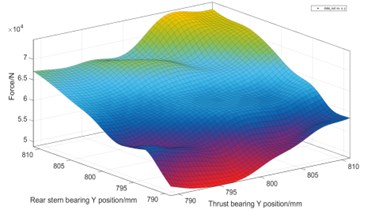
e) Force response surface of and
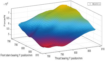
f) Force response surface of and
From Fig. 11, it is shown that the coupling response surface of the shaft inner diameter and the bearing vertical position is nearly linear, while the coupling response surface between the vertical positions of the shafts is non-linear. The load of the tail bearing decreases with the increase of the radius. The higher the vertical position of the bearing, the greater the load of the stern bearing, indicating that the thrust bearing has the greatest influence coefficient on the whole shafting. When the thrust bearing is too high, the intermediate bearing will be empty.
Fig. 12Stiffness response surface of rear stern bearing oil film
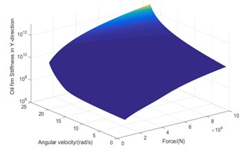
a)-direction stiffness response surface of rear stern bearing
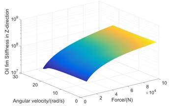
b)-direction stiffness response surface of rear stern bearing
According to the approximate equation of oil film stiffness characteristics, it can be seen that the physical and chemical characteristics of lubricating oil itself are relatively stable under stable operation, and the stiffness characteristics of oil film are mainly affected by shaft rotation speed and bearing load. Secondary approximate response surface of bearing load-speed-oil film stiffness is further obtained by RBF neural network learning, as shown in Fig. 12.
4. Shafting multidisciplinary design optimization
4.1. Objective functions
The parameters of shafting alignment quality index include bearing support reaction force, shaft curve deflection and inter-shaft deflection. The parameters of shafting whirling vibration performance index include displacement amplitude, natural frequency and response amplitude of bearing force.
In order to simplify the calculation, the deflection of the shaft curve and the deflection angle between the segments are taken as computational constraints in the process of calculation. In order to avoid resonance and make the first-order natural frequency of the whirling vibration larger than the first critical speed of the shafting, the support reaction force at three bearings (1, 2, 3), the amplitude of three bearing monitoring points (1, 2, 3), the amplitude of the stern shaft monitoring point, the minimum safety factor of the shaft segment and first-order natural frequency in the multidisciplinary calculation model of the shafting are finally selected as the optimized objective variables, as shown in Table 2.
Table 2Objective variables of optimization
Variable number | Symbol | Meaning | Unit |
1-3 | Bearing load | N | |
4-6 | Maximum amplitude of each bearing | mm | |
7 | Safety factor | mm | |
8 | First order natural frequency | Hz | |
9 | Maximum amplitude of the tail shaft | mm |
In order to improve the sensitivity of optimization parameters, the objective parameters are dimensionless, and the optimization rate index is defined as follows:
where, is the initial value of the optimized parameters; is the value after the parameter optimization. the optimization rate is used to represent the optimization degree of the parameters in the table, so the dimensionless objective function can be further constructed:
where, is the optimization variable numbered and is the optimization weight numbered . According to the fuzzy comprehensive evaluation method based on Quality Function Deployment (QFD) [27-28], the weight matrix is given as follows:
Referring to the construction rules of fitness function in genetic algorithm, the fitness function is further obtained:
4.2. Optimization algorithm
According to the multi-disciplinary cross over model of shafting, fireworks algorithm was adopted as the optimization algorithm to accelerate the convergence of optimization and ensure the wholeness of optimization results.
The optimization mechanism of fireworks algorithm is similar to that of genetic algorithm, but the mechanism of controlling how much the sparks generated by fireworks within the explosion radius by explosion operator. The explosion radius makes the population with higher fitness produce more offspring in a smaller numerical range, and the population with lower fitness produce more dispersed and fewer offspring in a larger numerical range, which can better solve the optimal value search ability of the seven-dimensional design variables in this paper. The multi-disciplinary optimization process of Shafting based on fireworks algorithm is shown in Fig. 13.
Fig. 13Fireworks algorithm optimization process
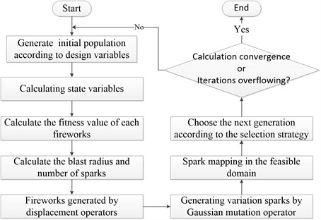
Firstly, based on the principle of uniform randomness, the initial fireworks population was generated in the feasible region of each dimension design variable. After the preliminary calculation of the multi-disciplinary model of shafting, the fitness values of individuals in the initial population are calculated. The initial values of design variables and the feasible region are shown in Table 3.
Table 3The variables of optimum design
Number | Symbol | Meaning | Unit | Initial value | Optimization range |
1 | Rear stern bearing vertical position | mm | 800 | [–10, 10] | |
2 | Front stern bearing vertical position | mm | 800 | [–10, 10] | |
3 | Thrust bearing vertical position | mm | 800 | [–10, 10] | |
4 | Rear stern bearing axial position | mm | 1369 | [–100, 100] | |
5 | Front stern bearing axial position | mm | 8552 | [–100, 100] | |
6 | Thrust bearing axial position | mm | 13250 | [–100, 100] | |
7 | Inner radius of the shaft | mm | 160 | [–10, 10] |
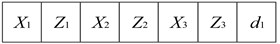
The coding of each individual firework is set as follows in Fig. 14.
In Fig. 14, represents the vertical position coding section of bearing , represents the fulcrum position of bearing , and represents the inner diameter of shaft . For vertical position , axial fulcrum position and inner diameter , the accuracy of 0.01mm is selected based on the actual technology and values. According to the coding rules, the coding section of each vertical position is 5 bits, the coding section of axial position is 7 bits, and the coding section of inner radius is 4 bits.
Fig. 14The encoding of designs variable
Then, according to the explosion operator, the explosion radius and the number of sparks generated by the explosion of the th firework are calculated. The sparks generated realize the migration and variation according to the migration rule and the mutation operator . The formula of the explosion radius is expressed as follows:
where, and are the minimum and maximum fitness values in the current fireworks population, is the minimum constant to avoid the denominator and being zero, is the fitness value of the th fireworks, is the total number of fireworks, and the constants and are the magnitude of explosion radius and the maximum spark value, respectively.
Migration rules and mutation operators can be represented as follows:
where, represents the random value of in [0, ], represents the function value of Gaussian distribution, both the mean and variance are 1; represents the dimension serial number of an individual.
Finally, the migration and variation of cross-border design variables are mapped to the feasible region by mapping rules. The individuals with the maximum fitness value are retained according to the selection strategy, and the random individuals are retained by referring to spark distance, and finally, the next generation of fireworks is screened. Mapping rules and selection strategies based on spark distance can be expressed as follows:
In the above formula, and represent the upper and lower bounds of the individual on the dimension respectively, % represents modular operators, represents the Euclidean distance between individuals, represents the Euclidean distance between individuals, represents the probability that each of the remaining individuals being kept randomly outside the best fitness individual, and represents the spark sets generated by explosion and mutation.
4.3. Optimization design results
Under the framework of multi-disciplinary optimization of shafting, the boundary conditions of optimization calculation should satisfy the following conditions:
1) For alignment calculation, each bearing load shall be within the upper limit [179.21 152.83 283.43] kN and the lower limit [11.43 7.85 6.28] kN;
2) The specific pressure of stern bearing shall not exceed 0.3MPa, and that of thrust bearing shall not exceed 0.25 MPa;
3) The safety factor of each section of the shafting should always be greater than 2.5;
4) The strength of each shaft segment shall meet the requirements, and the allowable stress ;
5) After optimization, the alignment technical parameters (e.g. deflection of shafting and rotation angle) and vibration technical parameters (e.g. anisotropic amplitude and critical speed), should meet the requirements in the specification [29-31].
The initial total number of fireworks is set as 2000 and the maximum spark is set as 1000 in the optimization algorithm. Through the joint simulation of MATLAB and finite element calculation, the internal diameter optimization value is 2.9 mm after iterative operation. The vertical displacement of rear stern bearing, front stern bearing and thrust bearing is [–8.89, 6.07, 0.72] mm, and the corresponding axial displacement is [–83.28, –44.6, –92, 55] respectively. Compared with the results of straight line alignment, the optimized results are shown in Fig. 14 and Table 4.
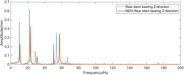
Fig. 15Whirling vibration frequency response curves of the bearing before and after MDO
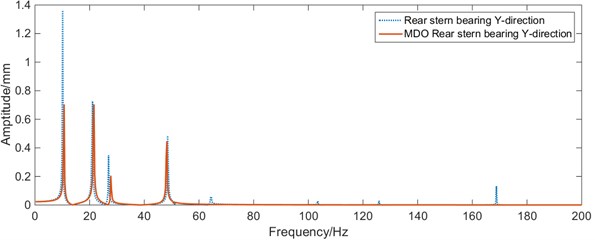
a)-direction vibration of rear stern bearing before and after MDO
b)-direction vibration of rear stern bearing before and after MDO
c)-direction vibration of front stern bearing before and after MDO
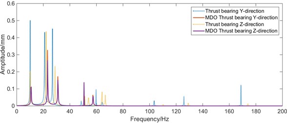
d)-direction vibration of thrust bearing before and after MDO
From Fig. 15, it can be seen that the load of the rear stern bearing in the shafting has been improved after optimization with MDO method, compared with the initial position and size of the shafting. Within 0-50 Hz, the maximum vibration of the rear stern bearing and the front stern bearing has been improved. The maximum amplitude at the stern bearing and the front stern bearing decreases significantly, and the maximum amplitude of whirling vibration at the stern shaft decreased from 7.58 mm to 5.69 mm; the first 6 natural frequencies of the shafting slightly increase, the whirling vibration characteristics of the shafting are improved significantly.
Fig. 16Calibration results of shafting alignment after MDO
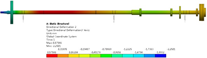
a) Deflection
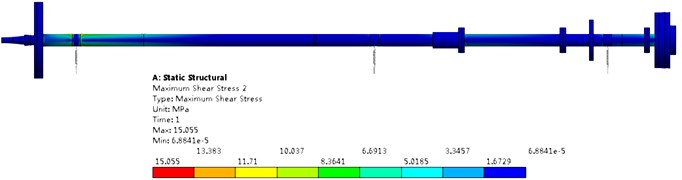
b) Equivalent stress
Table 4Comparison of objective variables before and after optimization
Variable name | Unit | Initial value | After MDO |
Rear stern bearing load | kN | 62.19 | 54.47 |
Front stern bearing load | kN | 18.25 | 40.41 |
Thrust bearing load | kN | 20.12 | 29.13 |
Rear stern bearing maximum amplitude | mm | 1.36 | 0.71 |
Front stern bearing maximum amplitude | mm | 0.71 | 0.32 |
Thrust bearing maximum amplitude | mm | 0.5 | 0.33 |
Tail shaft maximum amplitude | mm | 7.58 | 5.69 |
First order natural frequency | Hz | 10.09 | 10.58 |
Minimum safety factor | – | 9.25 | 5.5 |
By comparing Fig. 16 and Fig. 9, it can be seen that the maximum deflection of shafting increases from 0.4794 mm to 0.5759 mm, the maximum equivalent stress at the dangerous section decreases from 15.93 MPa to 15.06 MPa. It can be considered that the flexural characteristic of shafting is reduced, but the safety is increased. From Fig. 16 and Table 4, it can be seen that the load changes on each bearing are –7.72 kN, 22.16 kN, 9.01 kN, and the variations of load difference are 29.88 kN, 9.41 kN respectively. Although the loads of thrust bearing and front stern bearing are increased, the coincidence of the rear stern bearing is reduced, and the loading-distribution of the shafting is more uniform. It can be consider that the alignment characteristics of the shafting are improved.
5. Conclusions
In view of the lack of parallelism and discipline coupling in the existing design methods of ship shafting, this paper innovatively applies Multidisciplinary Design Optimization method in shafting design. The discipline decomposition of shafting is accomplished by structural design matrix, and an optimization framework of shafting multidisciplinary design based on multidisciplinary feasible method is constructed. The finite element method is used to establish the alignment calculation model and the whirling vibration calculation model of a certain shafting system. Based on the hydrodynamic lubrication theory, the oil film bearing support model is established. Based on the results of multidisciplinary cooperative operation, the response surface of bearing bi-directional displacement/inner diameter of shaft segment-bearing load-support stiffness is established, the decoupling between the dynamic stiffness, the alignment and whirling vibration was solved by the RBF neural network. The multidisciplinary optimization of seven-dimensional variable space of shafting design is accomplished by fireworks algorithm. Finally, the multidisciplinary design optimization of shafting alignment and whirling vibration based on bearing bi-directional displacement and shaft hollowness is realized. The load of rear stern bearing is effectively reduced, and the load distribution of each bearing is uniform. The amplitude-frequency characteristics of shafting in low frequency band are effectively improved. The feasibility of MDO in solving the comprehensive optimization problem between shafting vibration and alignment is verified. This study provides a new idea for the optimization of shafting design and has a certain reference value for future optimization design of actual shafting.
References
-
Chen G. J., Zeng F. M. Modern Ships Marine Engineering. National University of Defense Technology Press, Changsha, 2001, (in Chinese).
-
Jae-Ung Lee Application of strain gauge method for investigating influence of ship shaft movement by hydrodynamic propeller forces on shaft alignment. Measurement, Vol. 121, 2018, p. 261-275.
-
Dong G. K. Theoretical Research and Program Development of Propulsion Shafting Curve Alignment and Whirling Vibration. Huazhong University of Science and Technology, Wuhan, 2015.
-
Zhou R. P. Theoretical Study on the Super-Large Ship Propulsion Shafting. Wuhan University of Technology, Wuhan, 2005, (in Chinese).
-
Liu X. W., He Q. W., Lou J. J. Influence of shafting alignment state on bearing force transmission characteristics. Noise and Vibration Control, Vol. 36, Issue 4, 2016, p. 74-79, (in Chinese).
-
Zhou L. B., Duan Y., Sun Y. D. Summary of research on whirling vibration of surface propulsion shaft system. Noise and Vibration Control, Vol. 58, Issue 3, 2017, p. 233-244, (in Chinese).
-
Diken H., Alnefaie K. Effect of unbalanced rotor whirl on blade vibrations. Journal of Sound and Vibration, Vol. 330, 2011, p. 3498-3506.
-
Huang Y. X., Wang T. S., Zhao Y. Effect of axially functionally graded material on whirling frequencies and critical speeds of a spinning Timoshenko beam. Composite Structures, Vol. 20, 2018, p. 1-16, (in Chinese).
-
Murawski L., Ostachowicz W. Optimization of Marine Propulsion System’s Alignment for Aged Ships. Springer Berlin Heidelberg, 2010, p. 477-491.
-
Lin X. C. Research on Key Factors and Mechanism of Ship’s Propulsion Shaft whirling Vibration. Wuhan University of Technology, Wuhan, 2016, (in Chinese).
-
Fang G. Q. Research on correlation between shafting alignment and shafting vibration characteristic simulation. Ship Science and Technology, Vol. 38, Issue 1, 2016, p. 67-72, (in Chinese).
-
Lai G. J., Liu J. L., Liu S. Y. Comprehensive optimization for the alignment quality and whirling vibration damping of a motor drive shafting. Ocean Engineering, Vol. 157, 2018, p. 26-34.
-
Henderson K. Analysing the causes of propulsion shaft failure. Marine Propulsion and Auxiliary Machinery, 2010, p. 67-68.
-
Venkatachalam R., Balasivanandha Prabu Vibration Characteristics of Orthotropic Shaft-Disk System with Different Constrained Damping Layers Experimental and Numerical Study. Springer-Verlag London Limited, 2012.
-
Liu X. W., He Q. W., Jiang J. C. Optimal placement of bearings considering the alignment of the ship's shafting and bending vibration. Ship Science and Technology, Vol. 38, Issue 7, 2016, p. 44-49.
-
Kuang Q., Zhang C. Influence of ankle excitation on the whirling vibration of ship propulsion shafting. Ship Engineering, Vol. 39, Issue 1, 2017, p. 88-93, (in Chinese).
-
She H. X., Li C. F., Tang Q. S. The investigation of the coupled vibration in a flexible-disk blades system considering the influence of shaft bending vibration. Mechanical Systems and Signal Processing, Vol. 111, 2018, p. 545-569, (in Chinese).
-
Sobieszezanski Sobieski, Chopra I. Multidisciplinary optimization of aera nautical system. Journal of Aircraft, Vol. 12, 1990, p. 977-978.
-
Wang J. Application Research of Multidisciplinary Optimization Design in Underwater Unmanned Vehicle Design. Harbin Engineering University, Harbin, 2016, (in Chinese).
-
Yang L. Research on multidisciplinary design optimization of ship hydrodynamic performance. China Ship Research Institute, Beijing, 2017, (in Chinese).
-
Yi W. K. Research on Turbine Vibration and Shaft Stability of Ship Shafting Based on Parameterization. Huazhong University of Science and Technology, Wuhan, 2014, (in Chinese).
-
Chen L. Y. Research on Submarine Structure-Acoustic Radiation Optimization Based on Multidisciplinary Design Optimization. Shanghai Jiaotong University, Shanghai, 2008, (in Chinese).
-
Yukish M., Bennett L., Simpson T. W. Requirements on MDO imposed by the undersea vehicle conceptual design optimization. 8th Symposium on Multidisciplinary Analysis and Optimization, Long Beach, United States, 2000.
-
Pan B. B., Cui W. C. Multidisciplinary design optimization methods for ship design. Journal of Ship Mechanics, Vol. 12, Issue 6, 2008, p. 914-931, (in Chinese).
-
Yang H. J. Shaft alignment calculation considering oil film supporting force of stern tube bearing. Shipbuilding of China, Vol. 53, Issue 1, 2018, p. 142-149, (in Chinese).
-
Jiang J., Hu G., Li X., Xu X., Zheng P., Stringer J. Analysis and prediction of printable bridge length in fused deposition modelling based on back propagation neural network. Virtual and Physical Prototyping, Vol. 14, Issue 3, 2019, p. 253-266.
-
Liu J. L., Zeng F. M. Research on the calculation method for the requirement index weight of the marine power plant based on fuzzy AHP. Journal of Dalian Maritime University, Vol. 38, 2012, p. 35-38.
-
Liu J. L., Zeng F. M. Research on weight calculation method for requirement indexes of marine shaft system based on KANO model. International Symposium on Computational Intelligence and Design, 2016, p. 166-170.
-
Rules for the Classification of Steel Ships. China Classification Society, 2017, p. 259-276, (in Chinese).
-
Rules for Building and Classing Steel Vessels. American Bureau of Shipping, 2016, p. 217-220.
-
Rules for Classification of Ships. DetNorske Veritas, 2017, p. 402-405.
Cited by
About this article

The research leading to these results has received funding from the National Defense Science and Technology Foundation (20172B0815, 20191C080744), Hubei Natural Science Foundation (2014 CFB453, 2017 CFB584), Independent Project of Basic Research of Naval Engineering University (20161519) and National Defense Science and Technology project (20191C080744). All the supports mentioned above are gratefully acknowledged.
