Abstract
To reduce the transmission of shafting longitudinal vibration in surface ships, a design of thrust bearing integrated with internal disc springs is proposed and the longitudinal vibration characteristics of the shafting are studied. According to the structural characteristics of thrust bearing and the deformation characteristics of disc springs, the specific size and combination forms of disc springs in the thrust bearing are designed, and the effective disc springs schemes are achieved according to the static and dynamic design requirements. With the integration of the disc springs into the thrust bearing, the peak of longitudinal displacement response at the base of thrust bearing can be reduced by 10 dB by two schemes of disc springs. The proposed design can effectively suppress the transmission of shaft longitudinal vibration to the hull, which has engineering significance for the longitudinal vibration control of the shafting of the surface ship.
1. Introduction
The longitudinal vibration of a shafting is transmitted to the hull through the thrust bearing, which causes the hull’s vibration and then induces radiation noise. The longitudinal vibration of the propulsion shaft is one of the important sources of low-frequency noise at the stern of the ship [1]. Reducing the transmission of the shafting’s longitudinal vibration plays an important role in improving the comfort and noise level of ships.
The previous research shows that under longitudinal excitation, the thrust bearing is the main transmission path of stern vibration. If vibration control measures are taken at the thrust bearing, better results can be obtained for stern vibration control. To solve this problem, Dylejko et al. [1] carried out the vibration isolation analysis and optimization design of resonance changer in shafting shell coupling system on the basis of Goodwin [2]. Merz et al. [3, 4] studied the influence of active passive hybrid control system composed of resonance changer and distributed active vibration absorbers on shafting vibration and hull sound radiation. Zhang et al. [5] designed a low-frequency mounting system (LFMS) with floatable self-alignment thrust bearing to reduce the longitudinal vibration of shafting. Experiments showed that LFMS has an obvious vibration isolation effect above 10 Hz.
The stiffness of a thrust bearing and the base are generally large and difficult to change. Therefore, an isolation element with small stiffness could be connected in series at the thrust bearing to reduce the longitudinal vibration of the shafting. According to the structural characteristics of the thrust bearing of a surface ship, the isolation element can be connected in series between the thrust block and the thrust bearing shell.
Due to the characteristics of small internal space, large variation of lubricating oil temperature, large thrust force and complex working conditions of thrust bearing, higher performance requirements are necessary for the isolation elements in thrust bearing. Compared with other types of springs, such as coil springs, leaf springs, etc., disc springs have the advantages of high stiffness, small stroke and easy replacement. Meanwhile, different stiffness values can be obtained through different combination forms, which is convenient to meet the design requirements in engineering. It is a more suitable isolation element.
According to the structural characteristics of thrust bearing, the combination form and dimensional parameters of disc spring are designed and optimized, and the integrated disc spring thrust bearing scheme which meets the designed requirements is achieved. Then by the numerical study, the effect of the thrust bearing integrated with internal disc springs are discussed.
2. Longitudinal vibration model of shafting
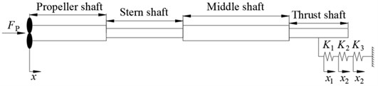
The shafting model in this study is shown in Fig. 1. Both ends of the shafting are free boundaries. The propeller is treated as a lumped mass. Due to only the longitudinal vibration of the shafting considered, each support bearing providing transverse stiffness can be ignored. The longitudinal stiffness of the shafting is provided by the thrust bearing, isolation element in series, and thrust bearing base. Their longitudinal stiffnesses are , and respectively. Under longitudinal excitation, the longitudinal displacement response at the propeller is , and those at the thrust bearing, isolation element and thrust bearing base are , and respectively.
Fig. 1The schematic diagram of a shafting
The material parameters and stiffness parameters are shown in Table 1. A preliminary calculation with finite element method shows that only when the stiffness of the isolation element meets 0.2e9 N/m 0.4e9 N/m, the longitudinal static deformation and vibration reduction effect of the shafting can satisfy the design requirement.
Table 1Material parameters and stiffness parameters of shafting
Parameter | Value |
Young’s modulus | 2.1e11 Pa |
Density | 7800 kg/m3 |
Poisson’s ratio | 0.3 |
Longitudinal stiffness of thrust bearing | 5e9 N/m |
Longitudinal stiffness of thrust bearing base | 1e9 N/m |
3. Design of disc springs’ combination form
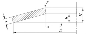
The structure of disc spring is shown in Fig. 2. and are the outer diameter and inner diameter of the disc spring respectively, is the thickness of the disc spring, is the calculated value of the deformation when the disc spring is fully pressed, and is free height of the disc spring.
The relationship between the applied load and displacement of disc spring can be calculated by A-L (Almen Laszlo) method:
where:
Fig. 2A schematic diagram of a disc spring
3.1. Design requirements
According to GB/T 1972-2005, the main difference between series A, B and C disc springs is that , are different, and the stiffness of series A disc spring is the largest. To ensure the small static deformation of the isolation element, the stiffness of a disc is required to be relatively large, therefore the series A disc spring is selected.
Assuming that the stiffness of a single disc spring is , the combination of the disc springs in this design is that disc springs are superimposed to form a unit, and then units are involuted to form a disc-spring group. Then s disc spring groups are evenly distributed around the thrust block. In this way, a thrust bearing integrated disc springs inside is formed. The disc spring superposition is equivalent to the spring parallel, and the involution is equivalent to spring series. Considering the friction between the disc spring surfaces during superposition, the total stiffness of the disc springs is:
where 0.03.
The longitudinal displacement responses at the nodes of thrust bearing, absorber and thrust bearing are:
Therefore, the relative deformation of single disc spring is:
From the above analysis, the overall stiffness of disc spring group, and the relative deformation of single disc spring under different combination forms can be obtained.
According to the relevant requirements of the shafting design, the first-order longitudinal vibration natural frequency of the shafting will not exceed certain value. For the static performance, it is also necessary to ensure that the disc spring will not produce excessive static deformation under the static excitation. The total target stiffness of the disc springs could be set within 0.2e9 N/m 0.4e9 N/m. In actual practice, the relative deformation of single disc spring is required to be between 20 %-75 %, so as to ensure its good linearity.
In addition, the size of the disc spring also needs to satisfy the internal installation space of the thrust bearing. Since the disc springs are installed between the thrust block and the thrust bearing shell, the number of disc spring groups needs to be consistent with the number of thrust blocks. For surface ships, the number of thrust blocks in the thrust bearing is generally 8, i.e. 8.
According to the above design requirements and referring to the size of the thrust disc in this design, the outer diameter of the disc spring is limited within 110 mm. The number of superimposed disc spring is required to be as few as possible to reduce the influence of friction. Selected from GB/T 1972-2005 A series, the results meeting the design requirements are shown in Table 2.
Table 2Disc spring combination scheme I
(n, m, s) | Total stiffness | Relative deformation | Total thickness | |||||
(mm) | (mm) | (mm) | (mm) | (mm) | (N/m) | (%) | (mm) | |
(2, 2, 8) | 100 | 51 | 6 | 2.2 | 8.2 | 0.231e9 | 62.93 | 28.4 |
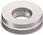
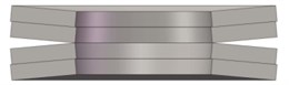
When is an even number, the upper and lower bearing surfaces shall contact the outer periphery of the disc spring to increase the contact area and maintain the stable and reliable operation of the disc spring group. Therefore, the specific combination form of scheme I is shown in Fig. 3.
Fig. 3Schematic diagram of disc spring combination in scheme I
After the disc springs are connected in series in the thrust bearing, the longitudinal static deformation of the shafting will increase under the excitation of static thrust. When the disc spring groups are fully pressed, the increment of the longitudinal static deformation of the shafting is the largest, 4.4 mm.
3.2. Parameter optimization design of disc spring
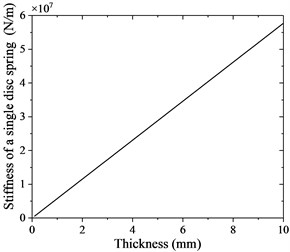
In the disc spring combination scheme obtained from the national standard selection, the disc spring has the form of superimposed, which will be greatly affected by the friction in the actual working condition. Therefore, it is necessary to design a scheme with only involution and no superposition. According to the A-L method, if is kept small, the disc spring with good linearity can be designed. Appropriate adjustment can be made according to the size proportion of series A disc spring to design a disc spring combination that meets the performance requirements without superposition. Take 16, 0.6, 0.4, and thickness at an interval of 0.1 mm, and take it from 0.1 mm to 10 mm to obtain the specifications of a new series of disc springs. The relationship between the single piece stiffness and thickness of this series of disc springs can be calculated by A-L method, as shown in Fig. 4.
Table 3Disc spring combination scheme II
(n, m, s) | Total stiffness | Relative deformation | Total thickness | |||||
(mm) | (mm) | (mm) | (mm) | (mm) | (N/m) | (%) | (mm) | |
(1, 1, 8) | 108.8 | 65.28 | 6.8 | 2.72 | 9.52 | 0.314e9 | 74.97 | 9.52 |
According to the design requirements in the previous section, the results meeting the requirements can be obtained, as shown in Table 3.
When the disc spring groups are fully pressed, the increment of the longitudinal static deformation of the shafting is the largest, 2.72 mm.
Fig. 4Single piece stiffness-thickness of new disc spring
3.3. Scheme comparison
The natural frequency of shafting longitudinal vibration from two schemes are shown in Table 4. It can be seen from the table that the first-order longitudinal natural frequency of shafting is reduced to 6.8 Hz and 7.4 Hz respectively after scheme I and scheme II are adopted. The second-order natural frequency is reduced from about 45 Hz to 38.6 Hz and 39.2 Hz.
Table 4Longitudinal natural frequency of shafting after installing disc spring (Hz)
Mode No. | Original shafting | Scheme I | Scheme II |
(2, 2, 8) | (1, 1, 8) | ||
1 | 11.135 | 6.817 | 7.468 |
2 | 44.992 | 38.610 | 39.218 |
3 | 83.869 | 80.148 | 80.442 |
To check the vibration reduction performance with the introducing of the disc springs in the thrust bearing, a unit longitudinal excitation force of 0-200 Hz is applied at the propeller, and the longitudinal vibration responses of the observation point at the thrust bearing base are calculated. The frequency response curve and power flow level curve of the two schemes at this observation point are shown in Fig. 5 and Fig. 6 respectively.
Fig. 5Displacement frequency response
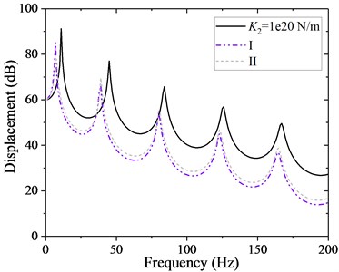
Fig. 6Power flow frequency response
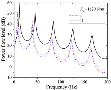
It can be seen from the figures that after the disc spring isolation thrust bearing is adopted, the response peaks of each order on the thrust bearing base move to the low frequency region, and the peaks of the response are significantly attenuated, about 10 dB, compared with those without disc springs installed. In terms of the vibration reduction effect, scheme Ⅰ is slightly better than scheme Ⅱ. It is should be pointed out that scheme Ⅰ adopts the form of superposition of discs, so that the performance of disc spring will be greatly affected by the friction between the superposition disc surfaces, also, the increment of shaft longitudinal deformation is greater for scheme Ⅰ. The comparison of advantages and disadvantages of two schemes is shown in Table 5, which can be selected according to the engineering requirements.
Table 5Comparison of advantages and disadvantages of the two schemes
Scheme Ⅰ | Scheme Ⅱ | |
(2, 2, 8) | (1, 1, 8) | |
Isolation effect | Fine | Fine |
Shafting maximum longitudinal deformation increment | 4.4 mm | 2.72 mm |
Design – practice discrepancy | Greatly affected by friction | Small |
Processing difficulty | Standard parts | Customized |
Installation difficulty | Guide element required | Direct installation |
4. Conclusions
Aiming at the control of low-frequency vibration at the stern of surface ship, a thrust bearing integrated with internal disc springs is proposed. By the static and dynamic analysis of the shafting with disc springs as vibration isolation element, a feasible scheme of disc spring group is formed. The following conclusions are drawn:
1) Through reasonable design, the isolation thrust bearing can effectively reduce the first-order natural frequency of shaft longitudinal vibration, and can effectively attenuate shaft longitudinal vibration in a large frequency range, with obvious effect of isolating displacement and energy.
2) Combined with the parameters of a shafting, two design schemes of thrust bearing integrated with disc springs are given to the control of longitudinal vibration. Both schemes have good performance on the longitudinal vibration control of shafting, which can be reasonably selected according to the design requirements and engineering practice.
References
-
P. G. Dylejko, N. J. Kessissoglou, Y. Tso, and C. J. Norwood, “Optimisation of a resonance changer to minimise the vibration transmission in marine vessels,” Journal of Sound and Vibration, Vol. 300, No. 1-2, pp. 101–116, Feb. 2007, https://doi.org/10.1016/j.jsv.2006.07.039
-
A. J. H. Goodwin, “The design of a resonance changer to overcome excessive axial vibration of propeller shafting,” Transactions of the Institute of Marine Engineers, Vol. 72, pp. 37–63, 1960.
-
Sascha Merz, Nicole Kessissoglou, Roger Kinns, and Steffen Marburg, “Optimisation of a submarine’s resonance changer using the method of moving asymptotes,” in Proceedings of Acoustics, Jan. 2009.
-
S. Merz, N. Kessissoglou, R. Kinns, and S. Marburg, “Minimisation of the sound power radiated by a submarine through optimisation of its resonance changer,” Journal of Sound and Vibration, Vol. 329, No. 8, pp. 980–993, Apr. 2010, https://doi.org/10.1016/j.jsv.2009.10.019
-
Y. Zhang, W. Xu, Z. Li, and L. Yin, “Design and dynamic analysis of low-frequency mounting system for marine thrust bearing,” Journal of the Brazilian Society of Mechanical Sciences and Engineering, Vol. 43, No. 2, p. 109, Feb. 2021, https://doi.org/10.1007/s40430-021-02840-w
Cited by
About this article

The authors wish to express their gratitude to the National Natural Science Foundation of China (Contract No. 51839005, 51609226 and 51879209) that have supported this work.
