Abstract
The influences of bearing support performance which would be affected by the quality of shafting alignment apparently on the lateral vibration natural frequencies of marine propulsion shafting are analyzed in this paper. A three dimensional finite element model representing the entire propulsion shafting, including the bearings, shaft and propeller, has been developed using finite element software for lateral vibration analyses. The effects of the number of bearings, the stiffness and effective contact length of the bearings on the natural frequencies of the shaft are studied respectively. The simulation analysis show that the bearing of a certain position often only has a significant impact on the frequencies of a certain order or a few orders, and the natural frequencies of the shaft can be transferred to avoid the resonance speeds through the reasonable arrangement and performance design of the shaft bearings. In addition, the curve alignment technology is also presented to improve the current shafting alignment quality and misalignment angle error, so as to ensure the design performance of radial bearings. Experimental results show that the curve alignment technology is an effective method to reduce the uneven load and eccentric wear of the bearings, which are beneficial to avoid the resonance vibration and improve the life and stability of shaft system.
1. Introduction
Marine propulsion shafting connects the main engine and propeller, and plays an important role in promoting the movement of ships. Along with the operation of shafting system, hydrodynamic forces acting on the propeller blades will produce bending moments and transverse forces on the shaft and cause various degrees of vibration [1]. If the natural frequencies of the vibration system are consistent with the excitation frequencies, resonance will be generated. For some devices, even if not in the resonance state, due to the increase of excitation, it may also cause severe vibration, and even affect the normal operation of the ship. Various vibration modes are coupled to different types of coupling vibration, which seriously threaten the safety and reliability of ships [2].
Misalignment is one of the most common sources of trouble of rotating machinery when rigid couplings connect the shafts due to the limitation of the current shafting alignment technology. Ideal alignment of the shafts is difficult to be obtained and rotors may present angular and/or parallel misalignment, such as bearing installation angle error,which also have influence on load condition of journal bearings. The performance of the bearing is directly influenced by the shafting alignment quality, thus affect the stability of the shaft system [3-5]. It found that [6] the bearing performance is greatly affected by the misalignment. The maximum pressure in the mid-plane is decreased by 20 % for the largest misalignment torque, while the minimum film thickness is reduced by 80 %.
In recent years, the interaction between the bearings and shafting system induced by misalignment and the eccentric wear of the bearings caused by large cantilever mass of the propeller, especially the problem of the inclination of the bearing have attracted wide attentions. Shi L. [7] analyzed the optimization method of the ship shafting alignment and its influence on the shafting through the finite element method, under the condition of the hull deformation and the wave load. Zou C. [8] studied the lateral vibration of rotor bearing system with rigid and flexible coupling by the Modal Synthesis Method. Nikolakopoulos P. [9] used the finite element method to solve the Reynolds equation and study the influence of the misalignment angle on the friction force and wear of the bearing. The theoretical model and numerical simulation of an angular misaligned rotor mounted in two hydrodynamic journal bearings were analyzed in order to survey the vibratory response of the misaligned rotor [10, 11]. When the shafting alignment is in poor condition, if the supporting force of the bearing is negative, or the bearing is void, the natural frequencies of transverse vibration will greatly decreased, and critical speeds may fall into the operating speed range.
Peng E. and Huang R. [12] applied methods of theoretical analysis, lubrication calculation and test to study the vibration characteristics of rubber stern tube bearing. The analyses show how friction-induced vibration generated and extended out of a function of effective measures to avoid abnormal vibration by improving the specific pressure and the surface roughness of rubber stern tube bearing. Lin T. [13] examined the vibration characteristics and vibration control method of complex ship structures. Relevant improved schemes for controlling the low frequency and high frequency vibration were proposed respectively, which were based on the engine supports. However, there was no way to regulate the frequencies of the system based on the radial bearings purposefully. Kessissoglou N. [14-16] researched on the application of resonance changer in the vibration and noise reduction. Resonance changer in the low frequency stage could play a very good role in the suppression of acoustic radiation, but at high frequency, it is still very limited.
Adjusting the natural frequencies of the vibration system is one of the main ways to avoid resonance. In this paper, the regulation of the spectrum distribution of the ship propulsion shafting based on the bearing support characteristics is studied. The natural frequencies and main vibration positions of the transverse vibration of the propeller shaft system are discussed in depth based on the finite element model. The effects of bearing failure, bearing stiffness and effective contact length on the resonance frequencies of the shaft are also studied respectively. In order to meet the supporting performance, improve the misalignment of the bearing and the uneven load distribution between bearings, a new shafting alignment method, which called curve alignment technique, is also raised [17, 18]. The Position-Pose measurement system of bearing hole based on image processing technology has also been developed to control the misalignment angle error [19, 20].
2. Analysis of natural frequencies of propulsion shafting
2.1. Finite element model of propulsion shafting
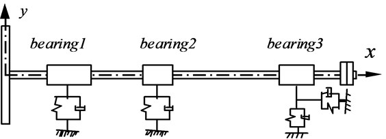
In order to facilitate the analysis, a marine propulsion shafting model, which contains the aft stern tube bearing (bearing 1), fore stern tube bearing (bearing 2) and thrust bearing (bearing 3), is established, based on a reduced scaled shafting test rig, as shown in Fig.1. The distance between the bearing 1 and the center of the propeller is 0.32 meters. The distances between the bearing 1 and bearing 2, bearing 2 and bearing 3 are 1.18 and 1.0237 meters respectively. Other main parameters of the model are shown in Table 1.
The finite element method is used to calculate and analyze the vibration modes of marine propulsion shafting, which has the advantages of simple and quick calculation. The modal analysis and harmonic response analysis are also able to be carried out by the finite element software. According to the vibration theory, there is a certain proportion of the displacement of each point in the Multi-Degree-of-Freedom (MDOF) system, when the system is vibrating at an inherent frequency. Each mode corresponds to a specific natural frequency, damping ratio and vibration type, which are the natural vibration characteristics of the mechanical structure.
Table 1The main parameters of shafting model
The main parameters of the model | Value |
Mass of the Propeller disc kg | 95 |
Diameter of shaft section m | 0.04 |
Elastic model of shaft section GPa | 210 |
Density of shaft section kg/m3 | 7900 |
Rigidity of the aft stern tube bearing N/m | 5×10⁸ |
Rigidity of forward stern tube bearing N/m | 1×10⁹ |
Radial rigidity of thrust bearing N/m | 1×10⁹ |
Axial rigidity of thrust bearing N/m | 1×10⁹ |
Fig. 1A propulsion shafting model
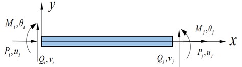
According to the dynamic characteristics of the ship propulsion shafting, two nodes element BEAM188 is used to represent the beam axis, as shown in Fig. 2. BEAM188 is a three-dimensional beam element and each node has six degrees of freedom: UX, UY, UZ, ROTX, ROTY, ROTZ. It is suitable for the analysis of slender beam structure such as shaft system, which could meet the requirements of various vibration calculations. COMBINE14 spring element, which is usually a linear spring element, was used to simulate the bearing characteristic of the elastic support. Three directions of freedom UX, UY, UZ can be expressed by COMBINE14 spring element, but the force can be transmitted only along the direction of the spring.
Fig. 2Two nodes element BEAM188 model
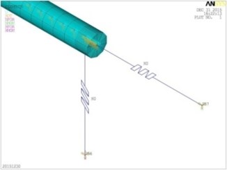
The finite element model of shafting test rig is established in ANSYS software, as shown in Fig. 3. The supports of the thrust bearing can be seen as a radial stiffness bearing and an axial stiffness support, as shown in Fig. 4.
Fig. 3The finite element model
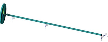
Fig. 4Finite element model of thrust bearing
After adding the displacement constraint and related boundary conditions, the modal analyses are carried out. The top six order natural frequencies of the transverse vibration of the propulsion shafting model are obtained. Natural frequencies of each order of the propulsion shafting test rig are shown in Table 2.
The vibration modes of each order frequency are also obtained, as shown in Fig. 5.
Table 2The natural frequencies of propulsion shafting test rig
Modal order | 1 | 2 | 3 | 4 | 5 | 6 |
(Hz) | 11.35 | 26.20 | 70.19 | 85.17 | 112.51 | 195.68 |
Fig. 5Vibration mode diagrams
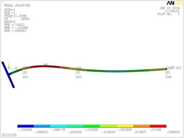
a) The first modal shape
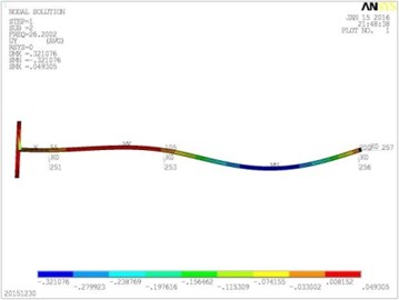
b) The second modal shape
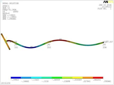
c) The third modal shape
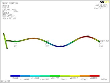
d) The fourth modal shape
Further, the harmonic response analysis, that is spectrum array of frequency-position are also carried out. A transverse exciting force which is changed with the time was applied on the center of the shaft system propeller, that is . The excitation frequency was gradually changed from 0 to 250 Hz by a certain step size. According to the harmonic response analysis, the response of the exciting force could be seen in different parts of the shafting on different frequencies, in order to find out the weak points of shafting, as shown in Fig. 6.
Fig. 6The spectrum array of frequency-position
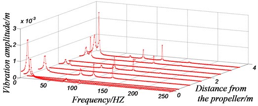
With the above mode diagrams and harmonic response analysis, the main vibration locations of the shafting system are different at different excitation frequencies. For example, according to the model, the vibration of the first order natural frequency of the propulsion shaft mainly occurs at the propeller. The vibration of the second order natural frequency of the shafting is mainly produced at the front end, which is near to the electric motor connected with elastic coupling. This phenomenon could also been confirmed in the spectrum array of frequency-position. Based on the peak distribution of vibration amplitude in 3D coordinates, it can be clearly determined that the vibration amplitudes of different position are different, when the exciting force is at different frequencies acting on the shaft. When the ship shafting is running at a certain speed, the main position of the vibration can be predicted. This provides an evidence for further adjusting of the shafting structure, so as to control the vibrations of critical elements purposefully and effectively.
2.2. The influence of the number of effective bearing supports on the natural frequencies
By the above analysis of natural frequencies, it is known that there is a very rich spectrum in the lower frequencies of the propulsion shafting, even if the shaft has more bearing supports. Due to the installation errors of shafting alignment, some bearings may be void or invalid sometimes. It is easy to fall into the range of natural frequencies due to the lower operating speed of the ship shafting, which can cause the resonance of the shafting and its parts. In this section, we will study the influence of disable or void ship shafting bearing, namely the number of effective bearing supports on the natural frequencies of propulsion shafting. Based on the structure of the existing shaft system model, the distribution of the natural frequencies of the shaft is analyzed, under the condition of the increase of stern tube intermediate bearing, intermediate bearing separately, or both bearings at the same time. That is, the shaft system consists of 3, 4 and 5 bearings respectively.
According to the calculation of the natural frequencies of the shaft which contains different number of bearing supports, the relationship of the number of effective bearing supports and the natural frequencies of the shaft is obtained, as shown in Fig. 7.
Fig. 7The relationship between the number of bearing supports and shaft’s natural frequencies. Note: Condition 1 refers to the shafting structure which contains the stern tube intermediate bearing compared to the original model. Condition 2 refers to the shafting structure which contains the intermediate bearing compared to the original model. Condition 3 refers to the shafting structure which contains the stern tube intermediate bearing and the intermediate bearing compared to the original model
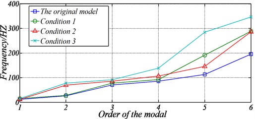
According to Fig. 7, the increase of the number of effective bearing supports would lead to the rise of the natural frequencies of the shaft. However, the locations of the bearing supports increased are different, and the degree of influence on the frequencies is not the same.
For example, when adding a stern tube intermediate bearing at the stern tube, the first natural frequency is increased from 11.345 Hz to 14.545 Hz, increased by 28.2 %, which is far greater than the growth rate 6.5 % of the second order natural frequency. When adding an intermediate bearing, the second order natural frequency is increased from 26.200 Hz to 69.832 Hz, increased by 155.5 %, but the first order natural frequency is almost constant. When the stern tube intermediate bearing and intermediate bearing are increased at the same time, the second order natural frequency increases from the 26.200 Hz to the 77.649 Hz, increased by 196.37 %, and the first order natural frequency is only increased by 28.4 %. That is to say, if resonance occurs at nearly 11 Hz in the ship shafting, the increase of stern tube intermediate bearing can significantly reduce the vibration, but increasing the intermediate bearing is almost no effect. It can be seen that the bearing of different positions of the shaft has a significant influence only on natural frequencies of a certain order or a few orders, where exists a corresponding relationship.
The reason of the difference is that the main vibration of first order mode of the shaft system occurs at the aft tube near the propeller. So, to increase the support constraint at the stern tube can produce a greater role in the regulation of the first order natural frequency. Other locations and corresponding frequencies also accord with this law. It can be seen that the number of effective bearings of the shaft has a great influence on the distribution of the natural frequencies, especially for the shaft which is long and has less bearings. The distribution of natural frequencies is usually more concentrated, and more modal’s natural frequencies are below 100 Hz.
So, it can be considered at the main vibration position to ensure the support characteristics of the bearings, and add effective bearing supports, to improve the natural frequencies of the shaft, which can avoid a certain resonance speed to a certain extent.
The reduction and deficiency of bearing supports due to poor shafting alignment may cause the decrease of the natural frequencies of shaft system. Therefore, more accurate installation and alignment of the propulsion shafting is required, which are of great significance to ensure the bearing performance and to avoid the resonance speed.
2.3. The influence of bearing stiffness on the natural frequencies of shaft system
In the course of ship propulsion shafting alignment, due to influence of bearing misalignment, bearing supporting stiffness will be affected to a certain extent, even though the bearing is not void. In order to study the influence of bearing stiffness on the shaft frequencies, based on the model of condition 3 mentioned above, the radial stiffness of the intermediate bearing or axial stiffness of the thrust bearing will be changed gradually. The study found that the axial stiffness of the thrust bearing has an influence on the spectrum distribution of the longitudinal vibration of the shafting, but it has no effect on the spectral distribution of the transverse vibration without consideration of coupling. By changing the longitudinal stiffness of the thrust bearing, the longitudinal vibration frequency spectrum distribution of the shafting can be adjusted. The effect of different radial support stiffness of intermediate bearing on the natural frequencies of the shaft is shown in Fig. 8.
Fig. 8The influence of intermediate bearing stiffness on the natural frequencies of shaft
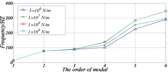
It can be seen from Fig.8 that in a certain range, the stiffness of intermediate bearing has a great influence on a certain order or a few order natural frequencies of the shaft. Along with the decrease of the bearing stiffness of the middle bearing, the natural frequencies of the shaft are reduced in different degrees.
However, for the intermediate bearings, its support stiffness has great influence on the fourth and above fourth order natural frequencies of the shafting, but little influence on the first order natural frequency. The reason is that the vibration displacement of the intermediate bearing is smaller under the first order vibration mode, but the vibration displacement is larger at other higher order frequencies. As a result, the stiffness of the support has a greater impact on the higher order frequencies than the lower order frequencies. In addition, the study also found that the aft stern tube bearing stiffness has more significant effect on the low order frequencies, especially the first order. So, when the ship propulsion shafting is running, more attention should be given to the stiffness of aft stern tube bearing.
The following corollaries can be obtained. According to the ship’s speed range, reasonable aft stern tube bearing stiffness can be designed to suppress the low frequency vibration of shafting and the supporting rigidity of a plurality of intermediate bearings can be adjusted appropriately for the higher order mode spectrum. But the basic premise is that the reasonable bearing installation process and the shafting alignment technology are needed to ensure the design effect.
2.4. The influence of effective contact length of bearing on natural frequencies
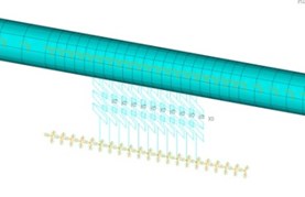
If uneven wear occurs at the end of the bearing induced by the poor shaft alignment or the installation angle error of bearings, effective bearing area, that is the effective contact length between the bearing and shafting will decrease, even be disengaged. In order to explore the effect of effective contact length of bearing on the natural frequencies of shaft system, the effective contact length of each bearing in the marine propulsion shafting is modeled in this section. A certain number of nodes with equal spacing are created to simulate the bearing divided into a number of segments. For each bearing, the effective contact length of each bearing can be reduced 10 mm each time by selecting the number of equal points, as shown in Fig. 9.
Fig. 9Multi nodes bearing model
Researches show that with the decrease of the effective contact length of the stern tube bearing, the natural frequencies of the shafting are gradually reduced. Because the lower frequency vibration is most concerned in the process of ship propulsion shafting operation, more attention should be given to the support state of aft stern tube bearing. The effective contact length of the stern tube bearing will affect the lower order natural frequencies of the shafting greatly, especially the first order and the third order natural frequencies, as shown in Table 3.
Table 3The relationship between vibration frequencies and effective contact length
/ mm | Natural frequency / Hz | |||
1st order | 2nd order | 3rd order | 4th order | |
100 | 23.096 | 29.905 | 97.897 | 138.76 |
90 | 22.242 | 29.905 | 94.824 | 138.71 |
80 | 21.404 | 29.905 | 91.895 | 138.62 |
70 | 20.552 | 29.905 | 89.017 | 138.42 |
60 | 19.639 | 29.905 | 86.071 | 138.07 |
50 | 18.590 | 29.905 | 82.911 | 137.48 |
40 | 17.301 | 29.905 | 79.408 | 136.61 |
The rule of the influence of effective contact length of aft stern tube bearing on the first order vibration natural frequency of propulsion shafting is clearly expressed in Fig. 10. Due to the limitation of the current shafting alignment technology, with the increase of wear of bearing end, the effective contact length of the bearing between the bearing and shafting decreases, and the 1st order natural frequency will also have a larger decline. For example, due to some factors, when the contact length of the aft stern tube bearing decrease from 100 mm to 50 mm, the 1st order natural frequency of the shaft reduced from 23.096 Hz to 18.590 Hz, reduced by19.51 %. When there is a big dip even disengaging between the bearing hole and the shaft, the decline will be greater.
Fig. 10The influence of effective contact length of aft stern tube bearing on the 1st order natural frequency
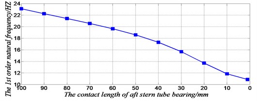
According to the data of Table 3, the effective contact length of the aft stern tube bearing has great influence on the 1st order and the 3rd order natural frequencies of the three-supporting shaft, but little effect on the 2nd order and 4th order frequencies, thus we call that the aft stern tube bearing is sensitive to the 1st order and 3rd order natural frequencies. The 1st order and 3th order vibration mode diagrams show that the amplitude of the stern near the aft stern tube bearing is relatively large, but is relatively smaller in the 2nd order and 4rd order vibration mode diagrams. So, when the contact length of the aft stern tube bearing is increased or diminished, which is equivalent to apply or reduce constraints on the stern tube bearing, the first order and third order vibration frequencies would change dramatically and be more sensitive,but the change of the 2nd and 4th order natural frequencies is very little. Other order vibration modes are also in line with this law. Therefore, in order to avoid the resonance of the shaft system, it is necessary to guarantee the ideal contact length of the bearings. If the propulsion shaft produces resonance in a certain speed, the length of the sensitive bearings can be optimized to achieve the transfer of spectrum.
3. Curve alignment technology of Ship propulsion shafting
Through the above analysis,bearing performance of ship propulsion shafting has a significant influence on the natural frequencies of the shafting. Therefore, improving the quality of the propulsion shafting has a positive effect on ensuring the design performance of the bearing and the stable running of the shaft.
Normally due to the gravity, the actual axis of the shaft is a curve after alignment. According to the current shafting alignment technology, the bearing angle cannot fully comply with the axis of the shaft curve. That is, there is a certain angle or called misalignment angle between the axle journal of the bearing support and the hole of the bearing. The uneven wear of the bearing can be caused by the misalignment, and the vibration and noise of the shaft will increase when the shafting alignment is poor or the load of the shafting is uneven, especially when the ratio of length to diameter of the bearing is relatively large.
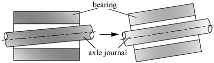
In order to ensure the supporting performance of the bearings of propulsion shafting, this paper proposed a new method of shafting alignment which is called the curve alignment technology. Namely the installation height of the bearings should be adjusted according to the load ratio of bearings, and bearings should be installed complied with the curve axis of shafting. The angle between the axle journal and the bearing bore should be strictly controlled, is almost 0 under ideal conditions, so that the average pressure of the bearing is almost equal, and the eccentric wear of the bearing is reduced, as shown in Fig. 11.
Fig. 11Relative position of bearing and the axle journal
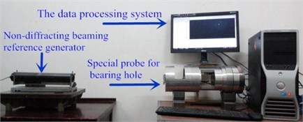
The Position-Pose measurement system of bearing hole, which is independently developed by Huazhong University of Science and Technology of China, can be used to measure the misalignment angle of bearing, as shown in Fig. 12. It could measure the deviations of five degrees of freedom of the bearing hole using the non-diffracting beam as the reference. The measurement accuracy of position and attitude of the bearing hole can be controlled in 0.03 mrad which is far more accurate than the 0.35 mrad specified in the standard for ship propulsion shafting alignment CB/Z 338-2005.
Fig. 12The Position-Pose measurement system of bearing hole
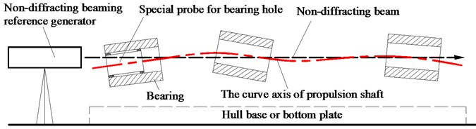
The measuring principle of Position-Pose measurement system of bearing hole is shown in Fig. 13. The reference line of the shaft system is reflected by a long distance non-diffraction optical spatial straight line reference and the spatial position and inclination angle of the bearing hole are measured by the special measuring probe through the image acquisition and processing. The ring spots would be formed in the binocular camera of the special probe, according to the image processing algorithm, the centers of the rings can be obtained, and it can be used to reflect the position deviation of the inner hole of the bearing with respect to the reference line. The measurement accuracy of the system is high, and it is suitable for the tolerance measurement of the large diameter ratio holes especially. In this way, the inclination angle between the bearing hole and the shaft neck is consistent, to ensure the uniformity of bearing load and reduce the eccentric wear.
Fig. 13The measuring principle of Position-Pose measurement system of bearing hole
According to the design scheme of Fig. 1, a three-support shaft test rig was installed using the curve alignment technology. In order to analyze the influence of shafting alignment method on the mechanical characteristics of the shaft, the transfer matrix method was used to calculate the axis of the shaft. The axis positions of the shaft corresponding to different bearing heights were shown in Fig. 14.
Fig. 14Calculation curves of shafting alignment
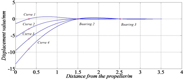
The heights of the aft stern tube bearing were set to 0, –3, –6, –9 mm respectively, and the corresponding curves were denoted by curve 1-4. The calculation results of shaft axis are shown in Table 4.
Table 4Calculation results of different axis curves
Items | Calculated curves | |||
Curve 1 | Curve 2 | Curve 3 | Curve 4 | |
Height of bearing 1 / mm | 0 | –3 | –6 | –9 |
Load of bearing 1 / N | –1236.7576 | –1153.79 | –1070.83 | –987.87 |
Load of bearing 2 / N | 279.8729 | 73.68 | –132.51 | –338.70 |
Load ratio of bearings | –4.42 | –15.66 | 8.08 | 2.92 |
Inclination angle / rad | 0.00341 | 0.00668 | 0.00995 | 0.01322 |
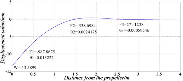
From Table 4, we can see that when the method of straight alignment was used, all bearings are of the same height and the supporting force of bearing 2 is negative, which indicates that bearing 2 is void. In addition, the load ratio of bearings is –4.42, and the installation angle error of bearing 1 is 0.00341 rad, which will cause the obvious misalignment of the bearing. The curve alignment method was used to adjust the height of bearing 1 continuously, in order to meet the requirements of bearing load. The calculation results show that when the height of bearing 1 was reduced to –9 mm, the load ratio was 2.92, and the calculated angle was 0.0132 rad, the axis curve of the shaft is shown in Fig. 15. The problems of load ratio and misalignment of bearings could be solved simultaneously, if the bearing was installed conformed to the shaft curve.
Fig. 15Curve axis of shaft after curve alignment technology
Furthermore, we show that misalignment of the bearing due to the gravity of the propeller and shaft section would have a significant impact on the bearing performance even if the misalignment angle is less than the standard 3.5×10⁻⁴ rad. The misalignment angle of the bearing can reduce the thickness of the liquid film, and the maximum film pressure increases significantly and moves towards one end or both ends of the bearing which would cause uneven load and eccentric wear of bearing. For example, for a plain bearing with a diameter of 225 mm, length of 470 mm, when the angle error between the axle journal and the bearing bore is 1.75×10⁻⁴ rad, the unilateral load pressure of liquid film increases by 47.7 %. In addition, misalignment angle of the bearing can also cause larger additional torque, which affects the stability of the shaft system.
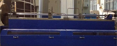
The three-support shaft test rig was installed and debugged according to the result of numerical calculation. The height of the aft stern tube bearing is 8.8 mm lower than other bearings finally, as shown in Fig. 16. The inclination angle of the bearing is adjusted to 0.0132 rad with the help of the feeler gauges according to the mechanical calculation and measurement of shafting, so that the angle of the bearing is complied with the curve axis of the shaft. The experimental results show that the system runs more stably and smoothly after the curve alignment technology. In addition, friction resistance, noise and uneven wear of bearings are also smaller than the commonly used shafting alignment technology.
Fig. 16A three-support shaft test rig
The run-out of the shaft’s end was measured by a dial indicator and running resistance was measured using a Newton gauge. The relevant experimental conditions were recorded in Table 5.
Table 5Experimental comparison of the shaft test rig
Items | Curve alignment | Straight alignment |
Bearing load ratio | 2.92 | –4.42 |
Installing angle error | ≈ 0 | 0.0038 rad |
Driving torque | 22.127 Nm | >59.75 Nm |
Operating noise | Lower limit of hearing | Obvious |
Operating condition | Run-out value < 0.1755 mm | Hard turning |
4. Conclusions
Aiming at the problem of ship shafting resonance vibration, the influences of bearing performance in the condition of the unreasonable shafting alignment on the natural frequencies of ship propulsion shafting were analyzed in this paper. The influences of the number of effective bearing supports, support stiffness and effective contact length of the bearings on the natural frequencies of the shaft system were studied respectively. The researches show that the alignment technology of ship propulsion shafting is very important to ensure the carrying capacity of the bearings and the stability of the shafting. It is pointed out that different vibration frequencies can be adjusted significantly merely by the bearings of specific positions. So according to the vibration characteristics of the shaft system, the corresponding bearing performance can be adjusted to control the vibration response of a certain frequency when the shaft is designed.
However, the performance of the bearing cannot meet the design requirements since current straight alignment technology and reasonable alignment technology cannot achieve the reasonable distribution of bearing load or high precision installation of the bearings. In order to ensure the installation precision and operation performance of the shaft, the curve alignment technology was put forward. To determine the height difference of each bearing according to pressure distribution and adjust the misalignment angle of bearings based on the curve of axis, and the installation accuracies of the bearings were also guaranteed by the Position-Pose measurement system. It provides a theoretical and technical basis for suppressing transverse vibration of shafting during the normal operation.
Based on the above systemic investigation, the main conclusions can be summarized as follows:
1) The load distribution and shafting vibration natural frequencies would be seriously affected by the decrease of the contact length or disengaging of bearings, which are caused by the unreasonable shafting alignment, additional moment, bearing wear or uneven friction.
2) According to the vibration mode diagram of shafting, the main vibration locations of any order natural frequency could be determined. So, the position of each bearing structure could be adjusted purposefully, by which method the corresponding frequencies can be effectively adjusted, to achieve the transfer of resonance spectrum, and avoid the resonance speeds.
3) The curve alignment technology of shaft system can guarantee the effective contact length and the performance of bearing supports effectively. This kind of shafting alignment technology should be further popularized. In this way, the bearing load is more evenly, eccentric wear is reduced, so that the shaft operation will be more stable and smooth.
References
-
Guidelines for the Control of Vibration on Ships. China Classification Society, China Communications Press, 2012.
-
Kaya M., Ozgumus O. Flexural-tensional-coupled vibration analysis of axially loaded closed-section composite Timoshenko beam by using DTM. Journal of Sound and Vibration, Vol. 306, 2007, p. 495-506.
-
Pennacchi P., Vania A., Chatterton S. Nonlinear effects caused by coupling misalignment in rotors equipped with journal bearings. Mechanical Systems and Signal Processing, Vol. 30, Issue 7, 2012, p. 306-322.
-
Mironov A., Ponomareva E. Impact of shaft fluctuations on the parameters of shafting “alignment”. Vestnik of Astrakhan State Technical University, Vol. 2, Issue 2014, 2014, p. 86-94.
-
Zhang Z., Chen F., Hua H. Analysis of friction-induced vibration in a propeller-shaft system with consideration of bearing-shaft friction. Proceedings of the Institution of Mechanical Engineers, Part C: Journal of Mechanical Engineering Science, Vol. 228, Issue 8, 2014, p. 1311-1328.
-
Bouyer J., Fillon M. An experimental analysis of misalignment effects on hydrodynamic plain journal bearing performances. Journal of Tribology, Vol. 124, Issue 2, 2002, p. 313-319.
-
Shi L., Xue D., Song X. Research on shafting alignment considering ship hull deformations. Marine Structures, Vol. 23, Issue 1, 2010, p. 103-114.
-
Zou C., Hua H., Chen D. Modal synthesis method of lateral vibration analysis for rotor-bearing system. Computers and Structures, Vol. 80, Issue 32, 2002, p. 2537-2549.
-
Nikolakopoulos P., Papadopoulos C. A study of friction in worn misaligned journal bearings under severe hydrodynamic lubrication. Tribology International, Vol. 41, Issue 6, 2008, p. 461-472.
-
Bouaziz S., Hili M., Mataar M. Dynamic behaviour of hydrodynamic journal bearings in presence of rotor spatial angular misalignment. Mechanism and Machine Theory, Vol. 44, Issue 8, 2009, p. 1548-1559.
-
Bouaziz S., Messaoud N., Mataar M. A theoretical model for analyzing the dynamic behavior of a misaligned rotor with active magnetic bearings. Mechatronics, Vol. 21, Issue 6, 2011, p. 899-907.
-
Peng E., Huang R. Tribology investigation in marine rubber stern tube bearing with consideration offriction-induced vibration. Proceedings of the Institution of Mechanical Engineers, Part J: Journal of Engineering Tribology, Vol. 39, Issue 4, 2015, p. 841-886.
-
Lin T., Pan J., O’Shea P., Mechefske C. A study of vibration and vibration control of ship structures. Marine Structures, Vol. 22, Issue 4, 2009, p. 730-743.
-
Dylejko P., Kessissoglou N., Yan T., Norwood C. Optimization of a resonance changer to minimise the vibration transmission in marine vessels. Journal of Sound and Vibration, Vol. 300, Issue 1, 2007, p. 101-116.
-
Merz S., Kinns R., Kessissoglou N. Structural and acoustic responses of a submarine hull due to propeller forces. Journal of Sound and Vibration, Vol. 325, Issue 1, 2009, p. 266-286.
-
Merz S., Kessissoglou N., Kinns R., Marburg S. Minimisation of the sound power radiated by a submarine through optimization of its resonance changer. Journal of Sound and Vibration, Vol. 329, Issue 8, 2010, p. 980-993.
-
Xinbao Z., Boqiang N., Qilong H. The light path analysis and system design of bearing hole pose measurement system based on the Non-diffraction beam. Journal of Hubei University of Technology, Vol. 29, Issue 5, 2014, p. 11-13.
-
Xinbao Z., Fei W., Guangkun D. Layout method of arrangement of bearing holes conforming to deflection curve. Ship Standardization Engineer, Vol. 48, 2015, p. 52-55.
-
Yuhui Z., Byeungwoo J., Danhua X., Jonathan W., Hui Z. Image segmentation by generalized hierarchical fuzzy C-means algorithm. Journal of Intelligent and Fuzzy Systems, Vol. 28, Issue 2, 2015, p. 961-973.
-
Zhihua X., Xinhui W., Xingming S., Quansheng L., Naixue X. Steganalysis of LSB matching using differences between nonadjacent pixels. Multimedia Tools and Applications, Vol. 75, Issue 4, 2016, p. 1947-1962.
Cited by
About this article

Support for this work from the National Natural Science Foundation of China (Grant No. 51375197) is gratefully acknowledged.
