Abstract
The analysis of rail/wheel sliding friction heat is a very important research field. The numerical simulation is often adopted to calculate the friction heat, and experimental method is relatively few. In this paper, an experimental machine is designed to simulate the rail/wheel sliding contact. At the same time, a rail/wheel contact wear model and a friction heat transfer model are established. The characteristics of temperature on rail/wheel sliding contact are analyzed by experimental test and numerical calculation. The research results show that the temperature rise of wheel and rail is quick in the initial sliding contact stage, then gradually slows down. The temperature of wheel is higher than that of rail at the same depth from the contact surface. In the initial sliding stage, the wheel temperature rises faster than the rail temperature, which is related to the size of contact surface and the concentration degree of friction heat. Moreover, the results of this paper show that the temperature values of the rail/wheel obtained through experimental test and numerical calculation are in good agreement. The experimental and numerical calculation methods used in this article can be adopted to analyze the contact problems of other sliding friction pairs.
Highlights
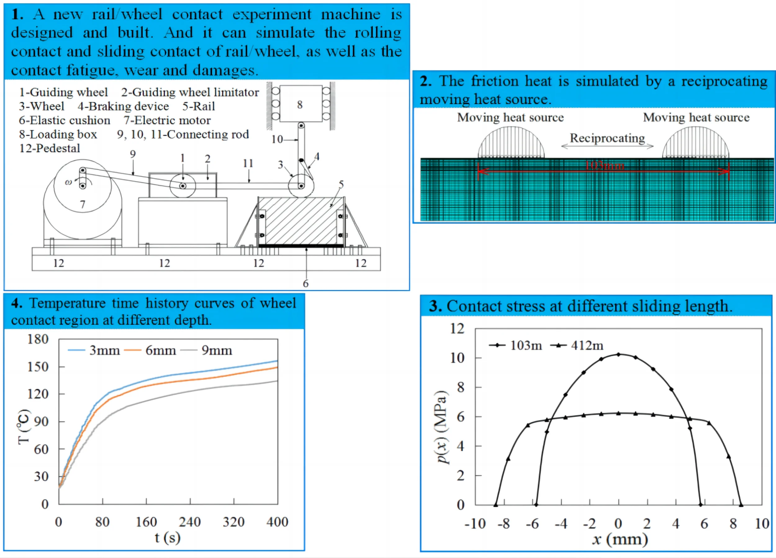
- A new type of rail/wheel contact experiment machine is designed and built, and is used to simulate rail/wheel contact.
- A rail/wheel contact wear model and a friction heat transfer model are established. The temperature-dependent mechanical parameters are adopted.
- A reciprocating heat source is employed to simulate the friction heat. The influences of wear on contact stress are fully considered.
- The temperatures of contact area are obtained by two methods of experimental measurement and numerical calculation, and the results are compared.
1. Introduction
The sliding contact between the friction pair is a common phenomenon in the mechanical, chemical and aerospace industries. Huge friction heat appears on the contact surface during rail/wheel sliding contact. Friction heat will change the microstructure of the contact material, and also influence the thermal and mechanical properties of the material [1]-[3]. The contact interface is in a very severe operating environment under the action of friction heat and mechanical load in railway transportation. Sliding contact occurs when the train is starting or braking, which is more obvious in the subways. Rail/wheel tread damages caused by sliding contact is a difficult question in railway transportation. Taking rail/wheel sliding contact as an example, a method of experimental test and numerical calculation is conducted in this paper to study the temperature rise during rail/wheel sliding contact.
Fig. 1(a) shows a wheel flat with a length of 85 mm, a width of 65 mm, and a depth of 2.5 mm due to sliding contact [4], [5]. In subways, the sliding contact is more frequent [6]. The rail/wheel damages caused by sliding contact have obvious influences on the safe operation and dynamic characteristics of trains. Ziwei Zhou et al. studied the impact of wheel flat on the dynamic characteristics of the vehicle-track system [7]-[9]. Mariusz Kostrzewski et al. summarized the methods used in different countries to monitor the status of rail transport systems during train operation, providing good suggestions for efficient and safe train operation [10].
The complex thermomechanical coupling phenomenon will appear on the contact surface during rail/wheel sliding contact. It is very meaningful to research the thermomechanical coupling relation, the influence of friction heat on the crystal structure of rail/wheel materials and the damages of contact interface. The basis of studying the thermal damages and the influence of temperature on materials is the temperature measurement and calculation. In the study of rail/wheel friction heat, the numerical calculations are mainly adopted to study the influences of different loads and sliding speeds on temperature, elastoplastic deformation and stress [11]-[14]. There are two typical numerical calculation models. In one model, the thermomechanical is directly coupled. And the other model is indirectly coupled, that is to say the temperature field (or stress field) of rail/wheel contact can be calculated firstly, and then the coupling analysis with stress field (or temperature field) is conducted. In indirect coupling model, the wheel and rail model can be established separately. The Hertz contact theory and Coulomb friction theory can be used to calculate the contact force and friction force respectively. And a moving heat source can be employed to simulate the rail/wheel friction heat [15], [16]. Compared with the numerical calculation method, there are few papers about the temperature measurement of rail/wheel contact region through experiments. In experiments, the thermocouple, thermal imaging camera, infrared thermometer are often adopted to measure the temperatures of rail/wheel contact region [17], [18].
Fig. 1Scratch of wheel caused by sliding contact
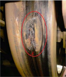
a) High-speed EMU
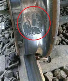
b) Normal-speed railway
The temperature of rail/wheel contact region obtained by numerical calculation in different papers has a great difference [11]-[13], [19]-[21]. These temperature values are not verified by experimental data and field tests. The main reason is that it is very difficult to directly measure the temperature values of rail/wheel contact surface. In order to ensure the reliability of numerical calculation method, a new experimental and numerical method is proposed. In this paper, an experimental machine is designed to simulate the rail/wheel sliding contact, and a temperature measuring device is adopted. At the same time, a rail/wheel sliding contact wear model and a friction heat transfer model are established, which are used to calculate the temperature of contact region. At last, the characteristics of temperature rise are studied, and the temperature data obtained by numerical calculation and experimental test are compared.
2. Experiment method
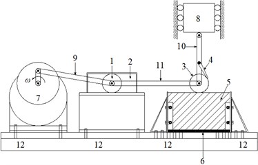
The rail/wheel experiment machine is designed in this paper (Fig. 2(a)), and its motion principle is illustrated in Fig. 2(b). The main components of machine are electric motor, wheel, rail, loading box, and etc. And the device can simulate the rolling contact and sliding contact of rail/wheel, as well as the contact fatigue, wear and damages. The vertical contact load applied between wheel and rail can reach 3500 N. In the experiment of this paper, the wheel slides back and forth on the rail surface, and then the temperature values of rail/wheel contact area are collected by temperature measuring device.
The wheel and rail used in experiment are shown in Fig. 3. The outer and inner diameters of wheel are respectively 80 mm and 10 mm. The length and height of rail are 240 mm and 40 mm respectively. The thickness of wheel and rail is 13 mm. The elastic modulus of rail/wheel is 216 GPa. The Poisson’s ratio is 0.31. The yield stress is 346.3 MPa. The wear coefficient is 2×10⁻⁴. The chemical composition and thermal parameters of rail/wheel material are listed in Table 1 and Table 2 respectively [19].
Fig. 2Schematic diagram of rail/wheel contact friction machine: 1 – guiding wheel, 2 – guiding wheel limitator, 3 – wheel, 4 – braking device, 5 – rail, 6 – elastic cushion, 7 – electric motor, 8 – loading box, 9, 10, 11 – connecting rod, 12 – pedestal
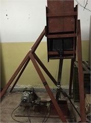
a) Experimental device
b) Components of experimental device
Fig. 3Component of wheel and rail
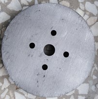
a) Wheel

b) Rail
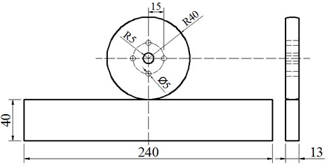
c) Size of wheel and rail (mm)
Table 1Chemical composition of rail/wheel material
Element | C | Mn | Si | Cr | Ni | P | S | Cu |
Elemental weight (%) | 0.42-0.50 | 0.50-0.80 | 0.17-0.37 | ≤ 0.25 | ≤ 0.25 | ≤ 0.035 | ≤ 0.035 | ≤ 0.25 |
Table 2Thermal parameters of rail/wheel material
T (℃) | Specific heat capacity (J/kg·℃) | Conductivity (W/m·℃) | Thermal expansion ×10-6(/℃) | Friction coefficient |
25 | 490.1 | 47.7 | 11.0 | 0.334 |
100 | 499.9 | 48.9 | 11.6 | 0.301 |
650 | 571.5 | 57.8 | 14.8 | 0.139 |
1000 | 617.1 | 63.4 | 15.7 | 0.085 |
1450 | 671.8 | 76.4 | 16.1 | 0.045 |
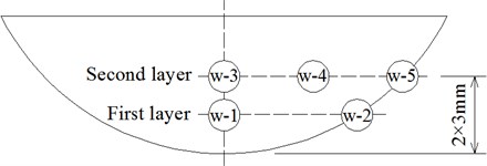
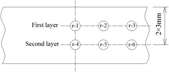
The FLEX-4015 temperature acquisition system and PT100 temperature sensor are employed to measure the temperature of rail/wheel sliding contact region, as shown in Fig. 4. The size of the temperature sensor is 2 mm × 2 mm × 1 mm. The temperature measurement range is –75 ℃-500 ℃, and its sensitivity is ±0.2 ℃. The locations of temperature sensors pasted on rail/wheel side surface are shown as Fig. 5 and Fig. 6. The wheel and rail presented in Fig. 5(a) and Fig. 6(a) are used to measure the temperatures along depth. In Fig. 5(b) and Fig. 6(b), the wheel and rail are employed to illustrate the distribution law of temperature field.
Fig. 4Temperature measurement tool

a) Temperature acquisition instrument
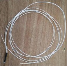
b) Temperature sensor
Fig. 5Location of temperature sensor on wheel side surface
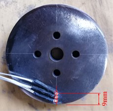
a) Depth
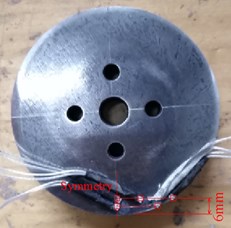
b) Transverse direction
Fig. 6Location of temperature sensor on rail side surface
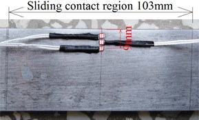
a) Depth
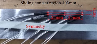
b) Transverse direction
3. Numerical method
During the experiment, the wheel slides on rail surface back and forth, the wear loss of wheel tread is large, and the contact stress between rail and wheel surface changes obviously. Therefore, a finite element wear model that simulates sliding contact is established, the contact stress is calculated during sliding contact firstly. Then the friction heat is calculated by:
where is temperature-dependent friction coefficient. is contact stress, which is wear-dependent and can be get from the wear model. is sliding speed. At last, the friction heat is applied to rail/wheel contact interface in the form of moving heat source.
3.1. Wear model of rail/wheel
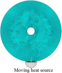
The wear model is shown as Fig. 7. In the model, PLANE182 element is selected to mesh the components of wheel and rail. CONTA171 and TARGE169 element are employed to simulate the contact behavior of rail/wheel. At the same time, the wear element is defined according to Archard theory. The model has 3576 nodes and 3580 elements. After many times of trial, the element size of contact region is set as 0.9 mm under the condition of meeting the requirement of calculation accuracy and speed.
Fig. 7Wear model of rail/wheel sliding contact

Multilinear isotropic hardening model is chosen to simulate the constitutive relationship of rail/wheel material, and the stress and strain are listed in Table 3. The load is 1000 N, and is applied at the center of wheel. The vertical displacement of rail bottom and the horizontal displacement at both ends of rail are constrained.
Table 3Stress and strain of rail/wheel material
Stress (MPa) | 346.3 | 354.6 | 494.6 | 512.4 | 524.3 | 530.2 |
Strain (×10-2) | 0.16 | 0.40 | 1.59 | 2.00 | 2.39 | 2.79 |
3.2. Friction heat transfer model
According to the wear model and Eq. (1), the friction heat can be calculated and applied to the rail and wheel models as a moving heat source (Fig. 8). The rail/wheel friction heat transfer model is an indirect coupling model, as shown in Fig. 8. The PLANE55 element, a 4-node plane solid element, is used to mesh the wheel and rail. The wheel has 6178 nodes and 6078 elements, and the minimum size of element is 0.03 mm. The rail has 9881 nodes and 9600 elements, the minimum element size is 0.46 mm. The geometric dimensions of the models are the same as the wheel and rail used in the experiment. The thermal parameters adopted in the model are listed in Table 2. The convective heat transfer coefficient between the rail/wheel surface and surrounding is 25 W/(m2·℃). The emissivity of rail/wheel is 0.82, and the Stefan-Boltzmann constant is 5.67×10⁻⁸ W/(m2·K4). The sliding speed of wheel is 1.0 m/s [22], [23].
Fig. 8Moving heat source of wheel and rail
a) Wheel
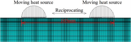
b) Rail
The contact patch size of rail/wheel increases with the growth of wheel wear depth, so the heat source applied to the wheel surface gradually widens (Fig. 8(a)). As shown in Fig. 8(b), the heat source moves on the rail surface back and forth, which simulates the friction heat of rail/wheel sliding contact in experiment. The widths and amplitudes of the moving heat source change with the wear loss. In other words, the moving heat source is wear-dependent. In the rail finite element model, the reciprocating motion of heat source is realized by load steps. And 93580 load steps in total are written to simulate the reciprocating movements of heat source.
4. Results
4.1. Contact stress
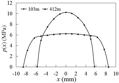
The wear on the wheel contact surface is very serious during rail/wheel sliding contact, and the contact stress between the rail and wheel changes greatly. Therefore, the wear-dependent contact stress is adopted to calculate the heat source. Fig. 9 shows the contact stress under the condition that the wheel sliding length is 103 m and 412 m respectively. Calculation results show that the maximum contact stress decreases rapidly with the increase of reciprocating movement length, and the contact width increases gradually. In the calculation of friction heat, the influence of wear on contact stress should be fully considered.
Fig. 9Contact stress at different sliding length
4.2. Experiment results
Fig. 10 indicates the temperature time history curves at different depths from the rail/wheel contact surface, and the temperature measuring positions are shown in Fig. 5(a) and Fig. 6(a). Fig. 10 shows the temperature rises quickly in the initial stage of sliding contact, and then slows down gradually. At the same time, the temperature decreases with the increase of distance to contact surface.
Fig. 10Temperature time history curves of rail/wheel at different depth
a) Wheel
b) Rail
Fig. 10 indicates the temperature rise of wheel is significantly quicker than that of rail at the same depth in the initial contact (< 70 s). During the rail/wheel sliding contact, the contact patch on wheel surface remains unchanged, and its size is small. The friction heat is relatively concentrated and can conduct to the interior of wheel quickly, and the dissipated heat is little. Therefore, the temperature rise is fast. However, the sliding contact area on rail surface is a long and narrow rectangle region, and its contact area is large. The friction heat is conducted to the interior of rail through contact patch. After the rail surface temperature rises, a part of heat stored in rial is dissipated into air. Compared with wheel, the rail contact surface is large, the heat is dispersed and is more easy to dissipate. Therefore, the temperature rise of rail is slower than that of wheel. After the rapid rising in the initial contact stage, the temperature of rail/wheel contact region is high, the heat dissipation gradually increases, so the temperature rise of rail/wheel contact region gradually slows down (> 70 s).
Fig. 11Temperature sensor number at different locations
a) Wheel
b) Rail
Fig. 12Temperature curves of wheel
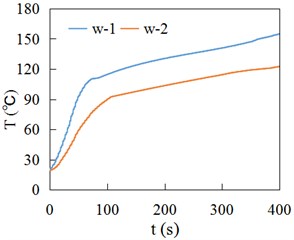
a) First layer
b) Second layer
Fig. 13Temperature curves of rail
a) First layer
b) Second layer
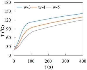
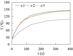
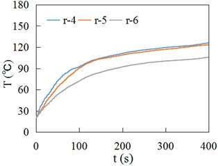
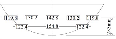
The temperature sensors in Fig. 5(b) and Fig. 6(b) are numbered in sequence, shown as Fig. 11. Fig. 12 and 13 respectively show the temperature time history curves of different measuring locations. Fig. 14 presents the temperature values at different measuring locations when sliding contact time is 400 s. Fig. 10(a), Fig. 12 and Fig. 14(a) indicate the temperature in the contact center of wheel is high, and then gradually decreases inward. The w-2 and w-5 are located at the edge of wheel tread, so the temperatures are relatively low. Due to the r-1 and r-2 points, r-4 and r-5 points are at the same depth in the middle of rail contact area, their temperature curves are very close (Fig. 13). The points of r-3 and r-6 are located at the end of sliding contact region, so their temperature is relatively low. Fig. 14 shows the wheel temperature is higher than rail temperature at the same depth at the contact center region.
Fig. 14Temperature of wheel and rail at different locations at 400 s (℃)
a) Wheel
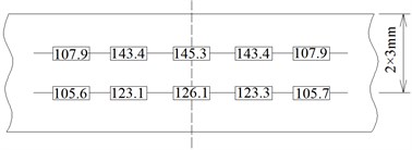
b) Rail
4.3. Numerical results and comparison
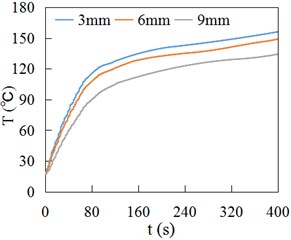
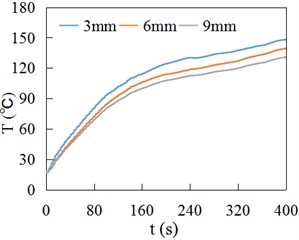
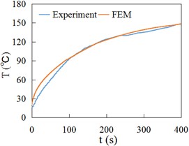
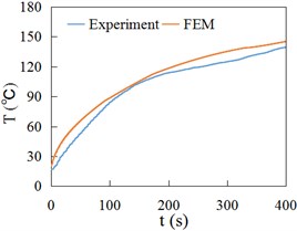
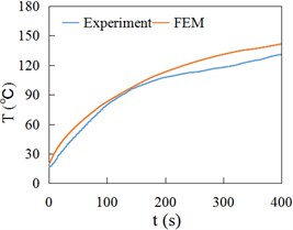
Fig. 15 and Fig. 16 respectively show the temperature time history curves obtained by experiment (Experiment) and finite element method (FEM) at the positions of 3 mm, 6 mm and 9 mm away from the contact surface of rail/wheel. Fig. 15 and Fig. 16 show the variation of FEM result curves is the same as the experiment measuring curves, namely rising rapidly at first and then slowing down gradually. Fig. 15 and Fig. 16 indicate that the FEM data are generally consistent with experiment values.
Fig. 15Temperature at different depths of wheel
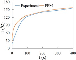
a) 3 mm
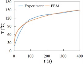
b) 6 mm
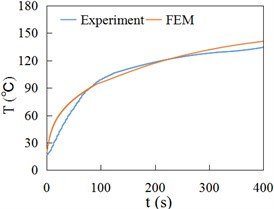
c) 9 mm
Fig. 16Temperature at different depths of rail
a) 3 mm
b) 6 mm
c) 9 mm
The temperature fields of wheel and rail calculated by the FEM are illustrated in Fig. 17. Fig. 14 and Fig. 17 indicate that the temperature in the contact center area is high, and decreases gradually outward from contact center. Compared with experiment data and numerical calculation results, the validity of method adopted in this paper has been proved.
Fig. 17Temperature field of wheel and rail obtained from FEM at 400s (℃)

a) Wheel
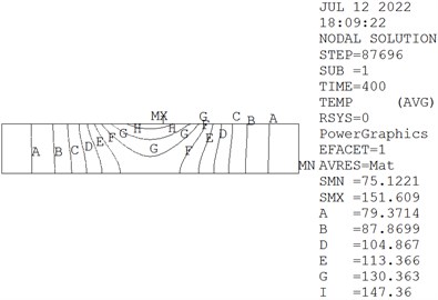
b) Rail
5. Discussion
The research results of References [1], [2] show that the phase transition phenomenon of surface material will occur during the rail/wheel sliding contact, and this phenomenon is also observed in the experiment conducted in this paper (Fig. 18). However, the phase transition is not considered in the numerical calculation in this paper. It is one of the key contents of future research to establish the rail/wheel direct thermomechanical coupling calculation model considering material phase transition.
Fig. 18Metal phase transition and adhesion

6. Conclusions
In this paper, an experimental and numerical calculation method for determining the rail/wheel sliding friction heat is proposed, and the temperature distribution and variation law of sliding contact region are studied. The main research results are as follows.
With the increase of the distance to rail/wheel contact interface, the temperature of contact region decreases gradually. The temperature of rail/wheel rises quickly in the initial sliding contact stage, and then the rising rate slows down gradually. At the same depth, the temperature of wheel is higher than rail temperature.
In the initial sliding stage, the rate of wheel temperature rise is greater than that of rail, which is related to the size of contact patch and the concentration degree of sliding friction heat. On wheel contact surface, the friction heat is concentrated and the contact area is small, so the temperature rise is fast. However, the contact area of rail is large and the heat is dispersed easily, so the temperature rise is slow.
The temperature time history curves at different positions and the temperature fields of rail/wheel contact region are obtained by means of experiment and numerical calculation, and the results obtained by two methods are in good agreement. It also indicates that the experimental and numerical methods proposed in this paper can be adopted to analyze the friction heat generated by sliding contact pair.
References
-
J. Ahlström and B. Karlsson, “Modelling of heat conduction and phase transformations during sliding of railway wheels,” Wear, Vol. 253, No. 1-2, pp. 291–300, Jul. 2002, https://doi.org/10.1016/s0043-1648(02)00119-9
-
J. Jergéus, “Martensite formation and residual stresses around railway wheel flats,” Proceedings of the Institution of Mechanical Engineers, Part C: Journal of Mechanical Engineering Science, Vol. 212, No. 1, pp. 69–79, Jan. 1998, https://doi.org/10.1243/0954406981521051
-
S. Caprioli and A. Ekberg, “Numerical evaluation of the material response of a railway wheel under thermomechanical braking conditions,” Wear, Vol. 314, No. 1-2, pp. 181–188, Jun. 2014, https://doi.org/10.1016/j.wear.2013.11.022
-
C. G. He, Y. Z. Chen, Y. B. Huang, Q. Y. Liu, M. H. Zhu, and W. J. Wang, “On the surface scratch and thermal fatigue damage of wheel material under different braking speed conditions,” Engineering Failure Analysis, Vol. 79, pp. 889–901, Sep. 2017, https://doi.org/10.1016/j.engfailanal.2017.06.017
-
Z. Ren, “Study on wheel/rail impact dynamics with three dimensional wheel flat model,” Journal of Mechanical Engineering, Vol. 54, No. 15, p. 78, 2018, https://doi.org/10.3901/jme.2018.15.078
-
S. Teimourimanesh, T. Vernersson, R. Lundén, F. Blennow, and M. Meinel, “Tread braking of railway wheels – temperatures generated by a metro train,” Proceedings of the Institution of Mechanical Engineers, Part F: Journal of Rail and Rapid Transit, Vol. 228, No. 2, pp. 210–221, Feb. 2014, https://doi.org/10.1177/0954409712470608
-
Z. Zhou et al., “Dynamic response feature of electromechanical coupled drive subsystem in a locomotive excited by wheel flat,” Engineering Failure Analysis, Vol. 122, p. 105248, Apr. 2021, https://doi.org/10.1016/j.engfailanal.2021.105248
-
L. Zhang, Z. Wang, Q. Wang, J. Mo, J. Feng, and K. Wang, “The effect of wheel polygonal wear on temperature and vibration characteristics of a high-speed train braking system,” Mechanical Systems and Signal Processing, Vol. 186, p. 109864, Mar. 2023, https://doi.org/10.1016/j.ymssp.2022.109864
-
J. Yang, Y. Zhao, J. Wang, C. Liu, and Y. Bai, “Influence of wheel flat on railway vehicle helical gear system under traction/braking conditions,” Engineering Failure Analysis, Vol. 134, p. 106022, Apr. 2022, https://doi.org/10.1016/j.engfailanal.2021.106022
-
M. Kostrzewski and R. Melnik, “Condition monitoring of rail transport systems: a bibliometric performance analysis and systematic literature review,” Sensors, Vol. 21, No. 14, p. 4710, Jul. 2021, https://doi.org/10.3390/s21144710
-
M. S. Walia, A. Esmaeili, T. Vernersson, and R. Lundén, “Thermomechanical capacity of wheel treads at stop braking: A parametric study,” International Journal of Fatigue, Vol. 113, pp. 407–415, Aug. 2018, https://doi.org/10.1016/j.ijfatigue.2018.04.031
-
M. Faccoli, L. Provezza, C. Petrogalli, A. Ghidini, and A. Mazzù, “Effects of full-stops on shoe-braked railway wheel wear damage,” Wear, Vol. 428-429, pp. 64–75, Jun. 2019, https://doi.org/10.1016/j.wear.2019.03.006
-
Y. Wu, Y. Wei, Y. Liu, Z. Duan, and L. Wang, “3-D analysis of thermal-mechanical behavior of wheel/rail sliding contact considering temperature characteristics of materials,” Applied Thermal Engineering, Vol. 115, pp. 455–462, Mar. 2017, https://doi.org/10.1016/j.applthermaleng.2016.12.136
-
A. Haidari and P. Hosseini-Tehrani, “Fatigue analysis of railway wheels under combined thermal and mechanical loads,” Journal of Thermal Stresses, Vol. 37, No. 1, pp. 34–50, Jan. 2014, https://doi.org/10.1080/01495739.2013.850967
-
Z. Y. Zhang et al., “Thermal model and temperature field in rail grinding process based on a moving heat source,” Applied Thermal Engineering, Vol. 106, pp. 855–864, Aug. 2016, https://doi.org/10.1016/j.applthermaleng.2016.06.071
-
L. Wu, Z. Wen, W. Li, and X. Jin, “Thermo-elastic-plastic finite element analysis of wheel/rail sliding contact,” Wear, Vol. 271, No. 1-2, pp. 437–443, May 2011, https://doi.org/10.1016/j.wear.2010.10.034
-
M. S. Walia, T. Vernersson, R. Lundén, F. Blennow, and M. Meinel, “Temperatures and wear at railway tread braking: field experiments and simulations,” Wear, Vol. 440-441, p. 203086, Dec. 2019, https://doi.org/10.1016/j.wear.2019.203086
-
T. Vernersson, “Temperatures at railway tread braking. Part 2: calibration and numerical examples,” Proceedings of the Institution of Mechanical Engineers, Part F: Journal of Rail and Rapid Transit, Vol. 221, No. 4, pp. 429–441, Jul. 2007, https://doi.org/10.1243/09544097jrrt90
-
Y.-C. Chen and S.-Y. Lee, “Elastic-plastic wheel-rail thermal contact on corrugated rails during wheel braking,” Journal of Tribology, Vol. 131, No. 1, Jan. 2009, https://doi.org/10.1115/1.2991163
-
T. Vernersson, “Temperatures at railway tread braking. Part 1: Modelling,” Proceedings of the Institution of Mechanical Engineers, Part F: Journal of Rail and Rapid Transit, Vol. 221, No. 2, pp. 167–182, Mar. 2007, https://doi.org/10.1243/0954409jrrt57
-
M. Milosevic, D. Stamenkovic, A. Milojevic, and M. Tomic, “Modeling thermal effects in braking systems of railway vehicles,” Thermal Science, Vol. 16, No. 2, pp. 515–526, 2012, https://doi.org/10.2298/tsci120503188m
-
M. Wang, Y.-H. Zhang, J. Bai, and L.-B. Wang, “Experimental study of convective heat transfer at the surface of a rail due to train passage,” Proceedings of the Institution of Mechanical Engineers, Part F: Journal of Rail and Rapid Transit, Vol. 229, No. 2, pp. 201–209, Feb. 2015, https://doi.org/10.1177/0954409713504567
-
Y. Wu, M. Wu, Y. Zhang, and L. Wang, “Experimental study of heat and mass transfer of a rolling wheel,” Heat and Mass Transfer, Vol. 50, No. 2, pp. 151–159, Feb. 2014, https://doi.org/10.1007/s00231-013-1228-6
Cited by
About this article

This study is supported by the Qinghai Youth Natural Science Foundation of China (Grant No. 2022-ZJ-960Q), the National Natural Science Foundation of China (Grant No. 51236003).
The datasets generated during and/or analyzed during the current study are available from the corresponding author on reasonable request.
The authors declare that they have no conflict of interest.
