Abstract
Pin on disc is a tribosystem confirming to ASTM G99, is employed in this work. It consists of deformable cylindrical disc and rigid pin with friction. Coating of Inconel 712 is added on stainless steel disc and pin is made of SiC3. The FEM software ANSYS R19.1 is employed for simulation of temperature distribution produced due to friction between pin on disc. Stress distribution is calculated from result produced between pin and disc interface due to applied contact load on pin. The governing equation is mentioned in introduction section. Result showing as contact load on pin increases maximum principle stress is increases. Temperature rises in direct proportion with sliding distance and time. Simulation result validates and confirmed with experimental results.
1. Introduction
Tribology is the study of science and technology of interacting surfaces in relative motion. It comprises the learning of friction, wear and lubrication [1]. It is been very difficult to reach and sustain a low coefficient of friction (COF) and wear rate (WR) at elevated temperatures. To maintaining low CoF (< 0.2) and WR (< 10-6 mm3/Nm) of coasting materials is a challenging task in field of tribology [2]. Coatings as well as substrate which can withstand at elevated temperatures and offers adaptability with change working conditions has significant role in machine components of industrial applications. For example, Aerospace industry (gears, rolling bearings, air foil bearings) [3] manufacturing Industry (Cutting tools, material forming dies), energy sector (Turbine bearings, Nuclear reactor core, thermal power plants, fusion and fission reactors, solar powers) [4] transportation industry (diesel engines piston rings, nuclear, space etc.) [5]. According to type of application, the coatings are required to be developed as such it will resist corrosion, wear, heat generation, diffusion of undesired species from working condition into the bulk coating materials and possess high temperature stability [6].
Pin on disc arrangements with sliding motion are commonly used to investigate tribological behavior of materials [7]. By this method one can establish relationships in various wear mechanisms with contact load, sliding speed and temperature. Also, wear rate and coefficient of friction. Wear analysis is always a complex part in tribology because it is a system property and not a material property [8]. FEM analysis of pin on disc arrangement is done by Suresh et al. [9]. Model for solving FEM equation is proposed by Podra et al. [10].
In this study coatings of Inconel 718 are used. Temperature and stress distribution are studied of pin on disc interface. Temperature distribution produces due to sliding of pin on disc with applied contact pressures is studied and reported. Stress field is produced and evaluated by simulation of model in ANSYS.
2. Material and methodology
Change in temperature due to friction on a body using ANSYS Workbench version R 19.1 and user-defined functions is analysed in this study. The user defined functions for degree of freedoms of temp in transient structural analysis considering the fact that structural analysis does not contains this function. The pin material used in this study is Inconel 712 and Disc materials is stainless steel.
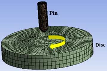
Open transient structural analysis in ANSYS Workbench import 3D geometry, Model is given in Fig1, open design modular expand the geometry tab to view all parts add command and type (et, matid, 226, 11) in command window. In this command 226 is element type and the number 11 is enabling extra degree of freedoms of temperature drag and drop that command option to the other part. Mechanical properties of pin on disc used in FEM simulation is given in Table 1.
Now define the contacts which can be found under the connections option now rename the contact region according to its definition. Enter the details for the contact region for the select option called frictional in definition tab, add frictional coefficient to 0.3 in the behavior tab change it to asymmetric, which is as having all contact elements on one surface and all target elements on the other surface. While in symmetric designate each surface to be both a target and a contact element. Change the formulation in advance tab to augmented Lagrangian, which is a certain class of algorithms for solving constrained optimization problems. Update stiffness to each iteration, it will add default contact stiffness is suitable for heavy contact where two parts “mash” into each other. So, by changing it to each iteration usually aids to convergence of solution. Now click on connections tab and in auto detection change the Generate automatic connection on refresh as no option because after this will keep our defined contacts same after each iteration. ANSYS cannot change the definition of the contacts. Now use UDF to define real constant of frictional contact add commands (key opt, cid, 1, 1; rmodif, cid, 16, 1; rmodif, cid, 10, 0, 5) where, (key opt, cid, 1, 1) = This enables temp as DOF for structural analysis. (rmodif, cid, 15, 1) = This defines the value of 15th real constant which is “FHTG” specifies the fraction of frictional dissipated energy converted into heat is given Eq. (1). (rmodif, cid, 18, 0.5) = This defines the value of 18th real constant which is “FWGT” specifies the weight factor for the distribution of heat between the contact and target surfaces for thermal contact. The basic heat dissipation equation for friction in ANSYS in the coupled thermal-structural contact modeling, the rate of frictional dissipation is given in Eq. (2):
where, – the equivalent frictional stress, – the sliding rate.
The amount of frictional dissipation on contact and target surfaces is defined by:
Now mesh the given geometry and choose sizing, in definition tab add element size as 5 mm. Now go to analysis setting in step controls tab change the number of steps to ten, step end time as 1 second, auto time stepping as on. Choose define by option to Time and define initial and minimum and maximum time steps as 0.1 s and 0.3 s and select all the 10 stop steps by pressing the shift key then insert initial and maximum time steps by ignoring the previous one because the latter definition takes care of all the sub steps. Now in the non-liner control option define the method for solution for that change the stabilization to constant value and insert the value of the energy dissipation ratio to 0.1 now we will use UDF to define thermal boundary conditions using ANSYS commands in transient (tref, 22; cnsel, s, temp; d, all, temp, 22; allsel, all) where tref 22 = defining reference temp; amsel, s, temp = select nodes on faces named as “temp” which we will define later; d, all, temp, 22 = assign initial value to the nodes. allsel, all = select all the entities on the face for solving. Geometric values of model is given in Table 2.
Fig. 1Geometry of the meshed modelled brick-on-slab arrangement in ANSYS
Now add name selection add “temp” on the top of the pingeometry. In connections add Body-Ground to fixed in mobile Tab in scope select lower face of slab. Select Body-Body in “reference” tab and select upper face of slab in scope. Then hide disc body and select the lower part of the brick in mobile tab of scope after that show all bodies. In transient option add pressure on top of the brick as 0.1 MPa. Add Joint load in transient option, in definition tab select velocity in type option and add magnitude value of 9 mm/sec. Under Translational option coordinate system need to be changed as such that brick will move in -direction. In solution and contact tool in this tab select geometry as top of the brick. Now expanded the contact tool clicked on status and change its type to sliding distance. In probe tab selection of joint option will open the boundary condition option in this transitional-disc to pin need to be selected. From the stress tab click on equivalent stress induce in structural analysis. Since there is no option of knowing the temperature, for this user-defined results need to be added, under this select expression tab and output unit will be changed as temperature. To know the temperature of the contact surface one need to be use bodies too and select that body from geometry options and repeat the same function as mentioned above. Now all the sub part of the solution is selected and renamed based on definition, this is done to avoid any sort of confusion after that solve button need to be clicked to solve the required model.
Table 1Mechanical properties of pin on disc used in FEM simulation
Yield stress | Youngs modulus | Poisson’s ratio | |
Inconel 712 | 649 MPa | 166 GPa | 0.29 |
Stainless steel | 211 MPa | 194 GPa | 0.32 |
Table 2Geometric values of model given in Fig. 1
Dimension of pin | Dimension of disc | Sliding speed | Coating thickness | Sliding distance | Load |
Diameter = 5 mm Height = 10 mm | Diameter = 40 mm Thickness = 10 mm | 3.5 m/sec | 0.05 mm | 2000 m | 50 N |
3. Results and discussion
3.1. Equivalent (Von-Mises) stress
Von mises stress is very commonly used study tribological behavior of contact parts it helps to understand that given model will withstand by applied load and it is derived from distortion energy failure theory. Result showing that maximum stress is 9.53 MPa and 0.0067 MPa. The maximum stress portion will be worn out which will be accounted for wear depth. Stresses produced are maximum at bottom of the brick and top surface of the slab. By increasing slab surface area, it will not under risk. So bottom portion of pin is highly weak part of this model. Result obtained from ANSYS is shown in Fig. 2. Result validated by numerical analysis with experimental results and it is found that results are in line with experimental one which is shown in Fig. 4.
Fig. 2Finite element model equivalent stress distribution in contact between pin on disc
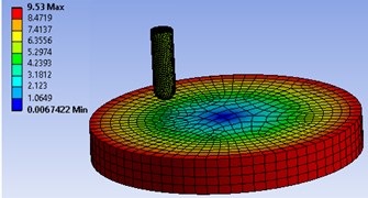
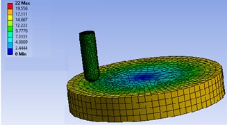
Fig. 3Finite element model temperature distribution in contact between pin on disc
3.2. Temperature distribution
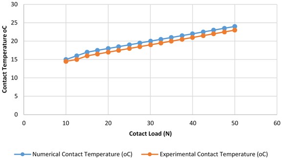
Heat produces as frictional force applied because of contact load. Temperature varies to maximum of 22 °C. As temperature increases more wear is occurring. Result showing that temperature is higher at contact zone and it move as disc is sliding. Result obtained from ANSYS is shown in Fig. 3. Result validated by numerical analysis with experimental results and it is found that results are in line with experimental one which is shown in Fig. 5.
Fig. 4Experimental and numerical results of contact pressure vs. applied load
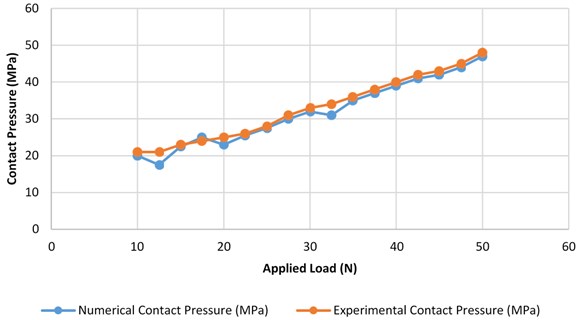
Fig. 5Experimental and numerical results of contact temperature vs. applied load
4. Conclusions
In this paper work pin on disctrobological behavior is tested and temperature distribution is reported, temperature is producing at the contact of pin on disc is producing increases as load and sliding speed is increasing. The 3D model is used for simulation in ANSYS. Result showing temperature is rises due friction. Heat is dissipating in both the pin on disc. Stress is pricing due to applied load on the brick which is also responsible for the rise in temperature.
References
-
Hutchings I., Shipway Philip Tribology Friction and Wear of Engineering Materials. 2nd Edition, 2017.
-
Liu Er-Yong, Wang Wen-Zhen, Gao Yi-Min, Jia Jun-Hong Tribological properties of Ni-based self-lubricating composites with addition of silver and molybdenum disulphide. Tribology International, Vol. 57, 2013, p. 235-241.
-
Holmberg K., Matthews A. Coatings Tribology. Elsevier Science, Vol. 28, 1994, p. 335-388.
-
Czichos H., Klaffke D., Santner E., Woydt M. Advances in tribology: the materials point of view. Wear, Vol. 190, 1995, p. 155-161.
-
Mateos J., Cuetos J. M., Vijande R., Fernandej E. Tribological properties of plasma sprayed and laserremelted 75/25 Cr3C2/NiCr coatings. Tribology International, Vol. 34, Issue 5, 2001, p. 345-351.
-
Blau P. J. Elevated-temperature tribology of metallic materials. Tribology International, Vol. 43, Issue 7, 2010, p. 1203-1208.
-
Stott F. H., Lin D. C., Wood G. C. Structure and mechanism of formation of the ‘Glaze’ oxide layers produced on Ni-based alloys during wear at high temperatures. Corrosion Science, Vol. 13, Issue 66, 1973, p. 449-469.
-
Jones M. H., Scott D. Industrial Tribology. Tribology Series No. 8. Elsevier, 1983.
-
Suresh R., Prasanna Kumar M., Basavarajappa S., Kiran T. S., Mahesh Yeole, Naresh Katare Numerical simulation and experimental study of wear depth and contact pressure distribution of aluminum MMC pin on disc tribometer. Materials Today: Proceedings, Vol. 4, 2017, p. 11218-11228.
-
Priit Podra, Soren Andersson Simulating sliding wear with finite element method. Tribology International, Vol. 32, 1999, p. 71-81.
About this article

