Abstract
During the process of starting, braking and running of the train, sliding contact between wheel and rail occurs. The wear caused by sliding contact exerts a noteworthy influence on the contact characteristics of wheel/rail. To analyze these characteristics, a three-dimensional wheel/rail contact wear model is established, and the contact characteristics at different wear depths are studied. The results indicate that at initial contact, the wheel/rail contact patch is approximately elliptical in shape and its area is 122.5 mm2. The von Mises stress of the wheel and rail is maximum in the subsurface at a distance of 2 mm from the contact interface, with maximum values of 559 MPa and 628 MPa respectively. When the wear depth is less than 0.5 mm, the wear depth, contact area and size increase quickly. As the amount of wheel contact wear increases, the maximum contact stress gradually decreases and the contact stress becomes uniform. In addition, the calculation results indicate that the contact patch shape does not always remain elliptical, the shape can change from elliptical to rectangular as the wear depth increases. As the increasing of wear amount, the contact stress gradient on the inner side of wheel contact surface increases.
Highlights
- A 3-D wheel/rail contact wear model including wheel, rail, rail pad, sleeper and foundation is established.
- The influence of sliding wear on wheel/rail contact characteristics has been studied.
- Wheel/rail contact stress and contact patch at different wear depths are obtained.
1. Introduction
With rapid development of rail transport industry, train speed and transportation density increase rapidly. In high-speed railways and heavy-load railways, the traction and braking performance of trains have faced increasingly high requirements. During the train braking process, the sliding wear on the wheel tread is very significant. The wear on the wheel/rail contact surface significantly influences the smoothness and safety of train operations, which increases the operating costs. The sliding contact can cause significant wear to the wheel tread and further change the geometry of the contact surface. Therefore, the contact characteristics of the wheel/rail will also change. Fig. 1(a) indicates a flat scar of 85 mm × 65 mm × 2.5 mm formed on the wheel tread of a high-speed railway due to sliding contact. Fig. 1(b) indicates the scratch on the wheel tread on a normal-speed railway [1]. The scratches on the wheel surface significantly affect the dynamic characteristics and safety of trains [2], [3].
Fig. 1Scratches and wear to wheel contact surface
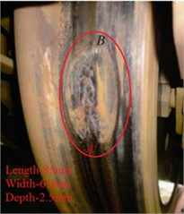
a) High-speed railway
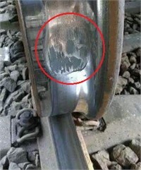
b) Normal-speed railway
The contact between the wheel and rail is a complex process, and the sliding wear of the contact surface is very obvious during wheel/rail sliding contact. Numerical methods are frequently employed to analyze wheel/rail contact. Sladkowski et al. established a three-dimensional (3-D) model to analyze the stress distribution in the contact region of wheel at varying angles of attack [4]. Yang et al. developed an implicit-explicit finite element model to simulate wheel creep problems and analyzed the distribution of residual stress [5]. W. Daves et al. investigated the wear, fatigue and damage under different contact conditions [6]. T. Ameyu et al. used a finite element model to simulate the moving load of an actual train and analyzed the dynamic response of elastic-plastic deformation, stress and friction heat [7]. The above numerical studies demonstrate that the speed, contact stress, contact position, rail cant and ambient temperature have a significant impact on the contact state and wear of the wheel/rail contact surface. At the same time, experimental methods are commonly used to study the wear and friction mechanism of wheel/rail. B. Elisa validated the wear and rolling fatigue model through experimental research in the laboratory [8]. P. J. Bolton conducted fatigue experiments to study the mechanism of wear and crack formation on the rolling contact surface, and obtained a large amount of data leading to wear [9]. J. W. Seo et al. used a twin-disc test machine to study the wear of the rail under rolling conditions, and the results show that the increase in wear has greatly shortened the life of the rails, and the maintenance cost has also been increased [10]. L. Zhou et al. conducted fatigue cycle experiments to analyze the impact of alternating temperatures on wheel/rail wear [11]. Ramalho. A et al. found that the growth of micro cyclic stress is also a major cause of wear [12]. The above experimental results are very important for understanding the mechanism of friction and wear. However, the influence of wear caused by sliding contact on the wheel/rail contact characteristics has not been fully studied.
Wheel/rail sliding contact is a commonly observed state of contact between the wheel/rail contact pair, and this phenomenon is general in heavy haul railways and subways. During sliding contact, a noteworthy thermal phenomenon occurs on the contact surface. Wang et al. [13]-[17] studied the thermo-mechanical characteristics of the contact region during wheel/rail sliding contact using the finite element method. However, the influence of sliding wear on the friction heat and contact characteristics is not considered in the research models. In fact, sliding wear can significantly change the geometric shape of contact surface, thereby affecting the contact characteristics. In this paper, a 3-D wheel/rail sliding contact wear finite element model is established first, then the contact characteristics (including the shape of contact patch, stress, etc.) in the sliding wear process are calculated, and finally the influence of sliding wear on contact characteristics is analyzed.
2. Contact wear model
In this paper, a numerical calculation method is employed to analyze the impact of sliding wear on contact characteristics. The sliding wear between wheel and rail is calculated according to Archard wear theory [18], it is:
where is wear rate, and represents the wear amount per unit area and per unit time. is the wear coefficient. is the wheel/rail relative sliding speed. represents the hardness of the material. is the contact stress on contact interface, and it can be calculated according to the extended Lagrangian algorithm, it is:
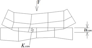
where is the wheel/rail normal contact stiffness. is the contact gap between the wheel and rail, as shown in Fig. 2. is:
where is the intrusion tolerance. is the Lagrange multiplier component at the -th iteration step.
Fig. 2Contact stiffness and contact gap
3. Finite element model
3.1. Wheel/rail sliding contact wear model
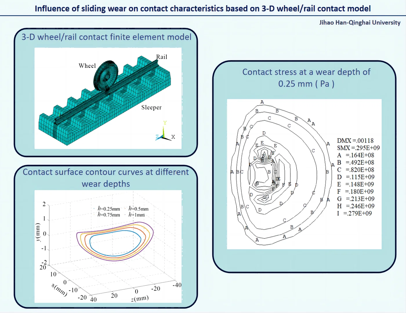
A 3-D wheel/rail contact wear model is constructed based on the actual wheel/rail dimensions using ANSYS software, shown as Fig. 3 [19]. The model contains wheel, rail, rail pad, sleeper and foundation (Fig. 3(a)). In the model, the SOLID185 solid element is chosen to simulate the wheel, rail, rail pad, sleeper and foundation (Fig. 3(b)). The wheel/rail contact behavior is simulated with CONTA174 element and TARGE170 element (Fig. 3(c)). Simultaneously, the wear elements are defined on the contact surface of wheel/rail based on Archard wear theory. Small size and fine element are designed in wheel/rail contact region because of stress concentration, and large size and coarse element are adopted in another region (Fig. 3(d)). Different size elements are connected by multi-point constraint method. The model has 147076 nodes and 147209 elements in total, and the minimum size of the element is 0.5 mm through multiple calculations.
Fig. 33-D wheel/rail contact wear model
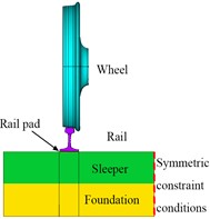
a) Wheel/rail-foundation vertical system
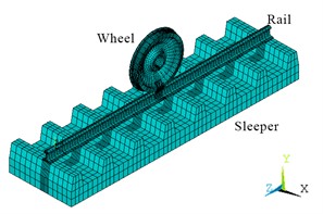
b) Finite element model
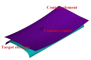
c) Wheel/rail contact pair
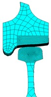
d) Wheel/rail contact in detail
3.2. Calculation parameters and boundary conditions
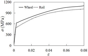
The dimensions of the wheel and rail are illustrated in Fig. 4(a) and Fig. 4(b), respectively. The LM-type wheel tread and S-shaped spoke are used in the model for wheel, and the diameter of wheel is 915 mm. The rail type is 60 kg/m standard rail. The length of rail in the model is 4.35 m, the rail cant is 1:40. The height and width of the rail sleeper is 0.25 m and 1.2 m, respectively. The sleeper gauge is 0.6 m. The material compositions and mechanical parameters are shown in Table 1 and Table 2, respectively. The coefficient of friction is 0.3. The wheel/rail material constitutive relationship is depicted in Fig. 5. The 100 kN load is applied to the wheel axle’s centre. The wear coefficient is 5×10⁻⁴ [20]. In the model, the lateral movement (-direction) of the wheel is constrained and is only allowed to slide along the rail. The two ends of the rail are constrained in both the longitudinal (-directional) and transverse (-directional) directions. The vertical displacement (-direction) of the foundation bottom is constrained. Symmetric constraint conditions are applied on the symmetry planes of the sleeper and the foundation (The red line in Fig. 3(a)).
Table 1Material compositions of wheel/rail
Materials | C (wt%) | Mn (wt%) | Si (wt%) | P (wt%) | S (wt%) | Cu (wt%) |
Wheel (CL60) | 0.57-0.65 | 0.75-1.10 | 0.15-0.35 | ≤ 0.025 | ≤ 0.020 | ≤ 0.20 |
Rail (U71Mn) | 0.65-0.77 | 1.10-1.50 | 0.15-0.40 | ≤ 0.035 | ≤ 0.035 | ≤ 0.20 |
Table 2Mechanical parameters of wheel/rail
Elastic modulus | Poisson’s ratio | Yield stress | Strength limit | Hardness | |
Wheel | 216 GPa | 0.3 | 628 MPa | 1110 MPa | 320 HB |
Rail | 215 GPa | 0.3 | 496 MPa | 1000 MPa | 300 HB |
Fig. 4Size of wheel/rail
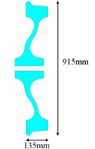
a) Wheel
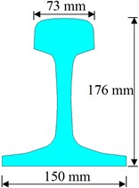
b) Rail
Fig. 5Constitutive relation of wheel/rail material
4. Results
4.1. Wheel/rail initial contact characteristics
Fig. 6 and Fig. 7 show the contact stress on the wheel/rail contact surface obtained by the finite element model and Hertz contact theory, respectively. Table 3 shows the maximum contact stress and the size of contact patch. Fig. 6, Fig. 7 and Table 3 illustrate that the contact patch of the wheel/rail is approximately elliptical in shape and its area is 122.5 mm2, and the maximum contact stress is close to 1200 MPa. At the same time, the calculation results show that the results obtained by using the finite element method and Hertz contact theory are relatively consistent, which also indicates the finite element model established in this paper is reasonable. Fig. 8 represents the von Mises stress contour maps in contact regions along longitudinal and transverse directions (Longitudinal direction refers to the direction along the length of the rail, and transverse direction refers to the direction perpendicular to the longitudinal direction). Fig. 8 indicates that the von Mises stress in the wheel/rail contact region is relatively concentrated and gradually decreases outward. The calculation shows that maximum von Mises stress of wheel and rail is located in the subsurface at a distance of 2 mm from the contact interface, the maximum value is 559 MPa and 628 MPa respectively.
Fig. 6Contact stress in finite element model
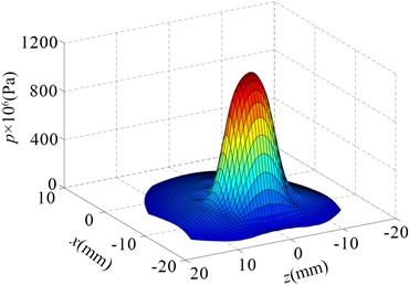
Fig. 7Hertz contact stress
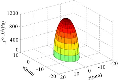
Table 3Contact stress and size of contact patch
Finite element model | Hertz contact theory | Error (%) | |
Contact stress | 1160 MPa | 1198 MPa | 3.2 |
Semi-major axis | 8.0 mm | 7.5 mm | 6.7 |
Semi-minor axis | 4.8 mm | 5.2 mm | 7.7 |
Contact area | 126 mm2 | 122.5 mm2 | 2.9 |
Fig. 8Von Mises stress in wheel/rail contact region (Pa)
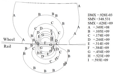
a) Longitudinal direction
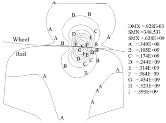
b) Transverse direction
4.2. Wear contact characteristics
The wheel/rail contact wear characteristics are obtained through the numerical model. Fig. 9 shows the profile of the worn wheel at wear depths () of 0.25 mm, 0.5 mm, 0.75 mm and 1 mm. Fig. 10 shows the contour maps of contact stress at different wear depths. Fig. 11 shows the maximum contact stress at different wear depths. Fig. 9 and Fig. 10 indicate that the contact area and size increase quickly when the wear depth is less than 0.5 mm. And subsequently the growth rate in contact size gradually decreased.
Fig. 9Contact surface contour curves at different wear depths
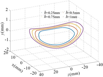
Fig. 10Contact stress at different wear depths (Pa)
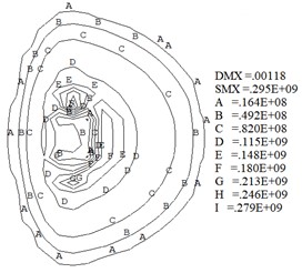
a)0.25 mm
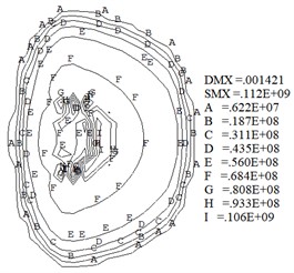
b)0.5 mm
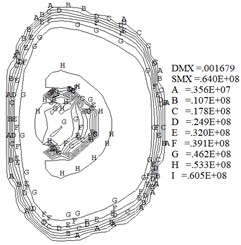
c)0.75 mm
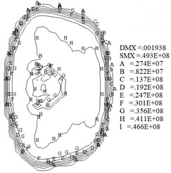
d)1 mm
Fig. 11Maximum contact stress at different wear depths
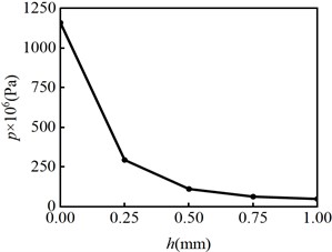
Fig. 10 indicates that the wheel/rail contact patch shape gradually changes from ellipse at the initial sliding contact ( 0.5 mm) to rectangle (0.5 mm 1mm ). Moreover, Fig. 10 shows the contact stress gradient on the inner side of wheel contact surface gradually increases. During train operation, the wheel inner tread is susceptible to developing sliding wear. Fig. 10 and Fig. 11 indicate the maximum contact stress decreases quickly when the wear depth is less than 0.5 mm. At the same time, the results show that the contact stress becomes more uniform as the wear amount increases. After the contact stress decreases, the wear rate decreases according to Eq. (1), and the rate of increase in wear depth and contact patch area gradually decrease.
5. Conclusions
Wheel/rail sliding contact is a common contact phenomenon in railway transportation, which leads to wear and significant changes in contact stress on the contact interface. The variation law of contact characteristics during wheel/rail sliding contact process is studied by numerical calculation. The main conclusions are the following.
1) At the initial contact, the contact patch between the wheel and rail is approximately elliptical and its area is 122.5 mm2. The stress concentration is clearly evident in the contact region between the wheel and rail, and the maximum von Mises stress of the wheel and rail appears in the subsurface of contact region, the maximum values are respectively 559 MPa and 628 MPa.
2) When the wear depth is less than 0.5 mm, the contact area and size increase quickly. As the amount of wheel contact wear increases, the maximum contact stress gradually decreases and the contact stress becomes more uniform.
3) The contact patch does not always remain elliptical. When the depth of wear surpasses 0.5 mm, the shape of the contact patch approaches a rectangle. As the increasing of wear amount, the contact stress gradient on the inner side of wheel contact surface increases, which indicates the inner side of the wheel tread is more prone to wear.
6. Discussion
In this article, a 3-D wheel/rail sliding contact wear model is established, and the influence of wear on contact characteristics is studied during wheel sliding contact process. The research results can clarify the changes in contact characteristics and provide a reference for the study of sliding friction heat. However, the influence of sliding friction heat is not considered in the calculation of sliding wear in the model. In fact, sliding wear, friction heat and contact force are coupled to each other, so it is not easy to achieve numerical calculation. At present, thermal-mechanical coupling model considering wear is being studied in order to obtain research results in the future.
References
-
Y. Wei and Y. Wu, “Experimental study on damage of the rail/wheel sliding contact surface in heavy-haul railway,” in Journal of Physics: Conference Series, Vol. 2381, No. 1, p. 012085, Dec. 2022, https://doi.org/10.1088/1742-6596/2381/1/012085
-
S. Chen, K. Wang, C. Chang, B. Xie, and W. Zhai, “A two-level adaptive chirp mode decomposition method for the railway wheel flat detection under variable-speed conditions,” Journal of Sound and Vibration, Vol. 498, No. 1, p. 115963, Apr. 2021, https://doi.org/10.1016/j.jsv.2021.115963
-
K. Murata and K. Nagakura, “Vibration characteristic of a wheel of a running railway vehicle,” Transactions of the Japan Society of Mechanical Engineers Series B, Vol. 78, No. 789, pp. 974–978, Jan. 2012, https://doi.org/10.1299/kikaib.78.974
-
A. Sladkowski and M. Sitarz, “Analysis of wheel-rail interaction using FE software,” Wear, Vol. 258, No. 7-8, pp. 1217–1223, Mar. 2005, https://doi.org/10.1016/j.wear.2004.03.032
-
L. Yang, M. Hu, D. Zhao, J. Yang, and X. Zhou, “Thermo-mechanical analysis of train wheel-rail contact using a novel finite-element model,” Industrial Lubrication and Tribology, Vol. 72, No. 5, pp. 687–693, Feb. 2020, https://doi.org/10.1108/ilt-07-2019-0298
-
W. Daves, W. Kubin, S. Scheriau, and M. Pletz, “A finite element model to simulate the physical mechanisms of wear and crack initiation in wheel/rail contact,” Wear, Vol. 366-367, pp. 78–83, Nov. 2016, https://doi.org/10.1016/j.wear.2016.05.027
-
A. Tucho, B. Indraratna, and T. Ngo, “Stress-deformation analysis of rail substructure under moving wheel load,” Transportation Geotechnics, Vol. 36, No. 4, p. 100805, Sep. 2022, https://doi.org/10.1016/j.trgeo.2022.100805
-
E. Butini et al., “An innovative model for the prediction of wheel – Rail wear and rolling contact fatigue,” Wear, Vol. 436-437, p. 203025, Oct. 2019, https://doi.org/10.1016/j.wear.2019.203025
-
P. J. Bolton, P. Clayton, and I. J. Mcewen, “Wear of rail and tire steels under rolling/sliding conditions,” A S L E Transactions, Vol. 25, No. 1, pp. 17–24, Mar. 2008, https://doi.org/10.1080/05698198208983059
-
J. W. Seo, H. K. Jun, S. J. Kwon, and D. H. Lee, “Rolling contact fatigue and wear behavior of rail steel under dry rolling-sliding contact condition,” Advanced Materials Research, Vol. 891-892, pp. 1545–1550, Mar. 2014, https://doi.org/10.4028/www.scientific.net/amr.891-892.1545
-
L. Zhou, Y. Hu, H. H. Ding, Q. Y. Liu, J. Guo, and W. J. Wang, “Experimental study on the wear and damage of wheel-rail steels under alternating temperature conditions,” Wear, Vol. 477, p. 203829, Jul. 2021, https://doi.org/10.1016/j.wear.2021.203829
-
A. Ramalho, M. Esteves, and P. Marta, “Friction and wear behaviour of rolling-sliding steel contacts,” Wear, Vol. 302, No. 1-2, pp. 1468–1480, Apr. 2013, https://doi.org/10.1016/j.wear.2012.12.008
-
W. J. Wang, R. Lewis, B. Yang, L. C. Guo, Q. Y. Liu, and M. H. Zhu, “Wear and damage transitions of wheel and rail materials under various contact conditions,” Wear, Vol. 362-363, pp. 146–152, Sep. 2016, https://doi.org/10.1016/j.wear.2016.05.021
-
L. Wu, Z. Wen, W. Li, and X. Jin, “Thermo-elastic-plastic finite element analysis of wheel/rail sliding contact,” Wear, Vol. 271, No. 1-2, pp. 437–443, May 2011, https://doi.org/10.1016/j.wear.2010.10.034
-
T. Vernersson, “Temperatures at railway tread braking. Part 1: modelling,” Proceedings of the Institution of Mechanical Engineers, Part F: Journal of Rail and Rapid Transit, Vol. 221, No. 2, pp. 167–182, Mar. 2007, https://doi.org/10.1243/0954409jrrt57
-
M. Naeimi et al., “Thermomechanical analysis of the wheel-rail contact using a coupled modelling procedure,” Tribology International, Vol. 117, pp. 250–260, Jan. 2018, https://doi.org/10.1016/j.triboint.2017.09.010
-
Y. Wu, Y. Wei, Y. Liu, Z. Duan, and L. Wang, “3-D analysis of thermal-mechanical behavior of wheel/rail sliding contact considering temperature characteristics of materials,” Applied Thermal Engineering, Vol. 115, pp. 455–462, Mar. 2017, https://doi.org/10.1016/j.applthermaleng.2016.12.136
-
J. F. Archard, “Contact and rubbing of flat surfaces,” Journal of Applied Physics, Vol. 24, No. 8, pp. 981–988, Aug. 1953, https://doi.org/10.1063/1.1721448
-
A. Polverino, A. Aversano, N. Rezazadeh, and S. Beneduce, “Numerical analysis on the propagation of ultrasonic guided wave in damaged carbon fiber reinforced polymer laminate,” Macromolecular Symposia, Vol. 411, No. 1, pp. 1–5, Oct. 2023, https://doi.org/10.1002/masy.202300017
-
S. Chen, “Influence of temperature rising of tread braking on wheel wear for heavy haul freight car,” (in Chinese), Journal of Mechanical Engineering, Vol. 53, No. 2, p. 92, Jan. 2017, https://doi.org/10.3901/jme.2017.02.092
Cited by
About this article

This study is supported by the Qinghai Youth Natural Science Foundation of China (Grant No. 2022-ZJ-960Q), the National Natural Science Foundation of China (Grant No. 51236003).
The datasets generated during and/or analyzed during the current study are available from the corresponding author on reasonable request.
Jihao Han: data curation, software, original draft preparation and editing. Yunpeng Wei: conceptualization, methodology, reviewing, editing and funding acquisition. Tao Yang: data curation and software.
The authors declare that they have no conflict of interest.
