Abstract
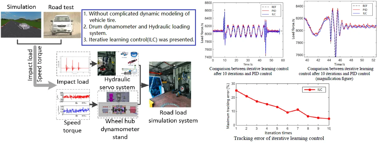
Fatigue and durability tests are important to develop or to optimize the vehicle drivetrain system. Using the vehicle drivetrain road load simulation test rig to reproduce the longitudinal driving load of the vehicle on the real road and the vertical impact load caused when the vehicle is on a bumpy pavement. In order to improve the control accuracy and convergence speed, an iterative learning control (ILC) method is presented. After 10 times of learning, the control error of iterative learning control method is 4.8 %, it is better than the 7.1 % error achieved by proportional-integral-derivative (PID) control. The simulation results demonstrate that the ILC can improve the convergence rate and increase the tracking accuracy than the PID control method.
Highlights
- Without complicated dynamic modeling of vehicle tire.
- Drum dynamometer and Hydraulic loading system.
- Iterative learning control (ILC) was presented.
1. Introduction
Fatigue and durability tests are important to develop or to optimize a product [1]. The vehicle drivetrain system reliability test is an important method to check and verify the durability of driveline. The vehicle drivetrain system is in a complex random variable load working state. When the vehicle passes through a bumpy pavement, the drivetrain system is affected by the longitudinal load torque of the wheel and the influence of the vertical load change. Therefore, when the vehicle drivetrain is tested, it is difficult to obtain the same results as those of the road test due to the change of the longitudinal torque load [2-4]. The road resistance remains the same when the vehicle is driving at a constant speed on a straight road, while the road resistance changes in real time, and the changes are very complicated when driving on bad roads, cross-country roads or bumpy roads (such as rough road, Belgian pave road, pebble road, etc.). And this change is transmitted to the vehicle drivetrain system through the driving wheels. When the vehicle surmounts obstacles, the vertical and longitudinal forces of the tire will change greatly [5], and that will have a great impact on the drivetrain system. Therefore, it is necessary to simulate the impact of bumpy pavement on the vehicle drivetrain system.
In recent years, indoor road simulation tests have been widely used to evaluate the fatigue durability of complete vehicles and components. Scholars have proposed remote parameter control methods, time domain control methods and so on, such as remote parameter control (RPC) software from the MTS company, iterative transfer function compensation (ITFC) control software from the Schenk company [6]. Some researchers have arranged different-shaped excitation patterns (traveling bumps) on the surface of the drum test bench to simulate the excitation of target pavement to obtain an effect like that of the traditional hydraulic servo road simulation [7]. In terms of road simulation load control methods, Ufuk Dursun et al. [8] established an inverse model of the system through the adaptive neuro-fuzzy inference system (ANFIS) with the auxiliary parameter (piston position) as a serial combination of two sub-models. They conduct extensive simulations that demonstrate the proposed single-layer and double-layer models. Mohammadi M. et al. [9] introduced a procedure to generate an accurate spatial working environment based on an existing real environment, the graphical software can be connected to the simulation software, which makes it possible to operate physics-based simulation models in their real environments. In order to develop simulation models adequate of real logistics facilities’ processes, Kostrzewski M. [10] used pseudorandom number generators (PRNGs) to provide actual data connected to material flows on entry to models. U. Koch et al. [11] proposed a model-based multi-axial (MIMO) state-space control of a car vibration test rig with four electromagnetic actuators for the tracking of road measurements. X. Wang et al. [12] proposed a method that combines the ILC with the Quasi-Newton algorithm over the complex space (QNILC) is developed to speed up the drive model construction for the multi-axial vibration test rig.
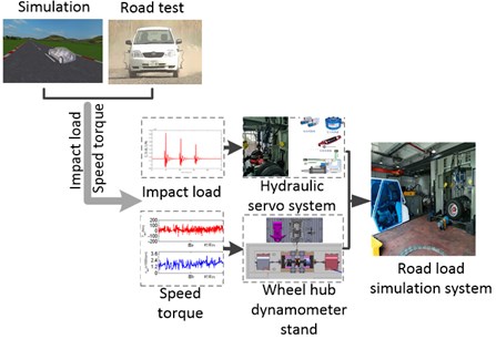
When a vehicle passes through bumpy roads, the drivetrain system is affected by both the longitudinal load torque of the wheels and the change of the vertical load. Therefore, in this paper, a road load simulation test system of vehicle drivetrain based on the drum dynamometer and hydraulic load system is established. The drum dynamometer is used to simulate vehicle longitudinal driving load resistance, and the hydraulic loading mechanism is used to simulate the change of vertical load on the drivetrain system when the vehicle passes through a bumpy road, so as to achieve a more realistic simulation of the working state of the drivetrain system during vehicle driving.
2. System structure and principle
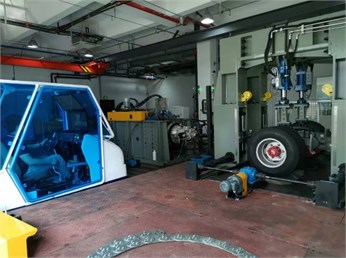
The road load simulation system of vehicle drivetrain based on the drum dynamometer is shown in Fig. 1, which is mainly composed of a load simulation system based on drum dynamometer, rive system and real-time controller. The load simulation system uses a rotary drum dynamometer to simulate the ground resistance to give the wheel load resistance. The wheel and drive axle, transmission shaft and transmission constitute the tested part of the drivetrain system. The input of the transmission relates to the drive motor to simulate the engine driving force. The drive axle uses a hydraulic loading system to provide the vertical loading force for simulating the vehicle load. At the same time, in order to test the gearshift performance and matching performance of the drivetrain, the simulation cockpit and driving simulation scene are configured, and the gearshift handle is connected to the simulation cockpit through the gearshift cable.
Fig. 1Road load simulation system of vehicle drivetrain system based on dynamometer
The simulation system involves the following functions and characteristics:
1) On the basis of the traditional stand of vehicle drivetrain, the drum dynamometer system for wheel and vehicle tests is introduced. Therefore, when dynamic modeling is carried out, the accuracy of simulation results is improved without complicated dynamic modeling of automobile tire.
2) The hydraulic loading system (composed of hydraulic servo valve, hydraulic cylinder, and guide rail) is used to actuate the sliding block of the driving axle housing to simulate the change of the vertical load on the drivetrain system when the vehicle passes the bumpy road, so as to achieve more realistic simulation of the working state of the drivetrain system during the driving process of the vehicle.
3) The simulation cockpit is used to provide steering wheel, accelerator pedal, brake pedal, clutch pedal, gearshift mechanism and simulation driving scene. The clutch pedal and gearshift mechanism are real vehicle matching parts, which can provide a more realistic driving environment for the simulation driver to carry out the vehicle driveline control performance and matching test.
4) The drum dynamometer system of road load simulation system of vehicle drivetrain system based on the drum dynamometer is driven by two load motors respectively. Compared with the scheme where one load motor drives two rotary drums of the traditional drum dynamometer, the drum dynamometer system driven by two motors can simulate the turning condition and simulate the differential speed test with the steering wheel.
3. Road impact load simulation method
The impact of tire load change to the output of axle is simulated when the vehicle is driving on bumpy roads. According to the automobile theory, the rolling resistance of the vehicle is equal to the product of wheel load and rolling resistance coefficient, i.e., . When the rolling resistance coefficient, , is constant, and the load, , is changed, the magnitude of the rolling resistance will change too, thus, the output load of the transmission system will change that will cause the operating speed of the engine to change. It is generally believed that the road resistance remains unchanged when the vehicle is traveling at a constant speed on a straight road. However, when the vehicle drives on a bad road, off-road, or bumpy road (such as rolling road, Belgium pave road, pebble road, etc.), the road resistance changes in real time, and the change is very complicated. And this change is transmitted to the vehicle driveline through the drive wheels. When the vehicle passes an obstacle, the vertical and longitudinal forces of the tire will change significantly. Studies have shown that the vertical load of the axle increases by about 60 % when the automobile tire passes through the bump of 15 mm × 15 mm at a speed of 10 km/h, and the periodic effect will occur when the vehicle speed is high that will have a great influence on the transmission system. Therefore, in order to simulate more accurately the effect of bumpy road impact load on the driveline performance when the vehicle is traveling, it is necessary to simulate the impact of the bumpy road on the automotive driveline. The vehicle driveline road load simulation system jointly developed by the author’s research group and automobile enterprises can simulate the vertical road impact load and longitudinal driving resistance load in the process of vehicle driving by combining the hydraulic servo loading system and the drum dynamometer (as shown in Fig. 2).
Fig. 2Schematic diagram for pavement impact load and longitudinal driving resistance load
4. Electro-hydraulic servo force loading model
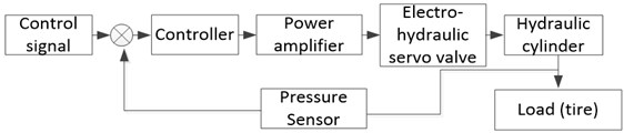
Electro-hydraulic servo loading system is a typical force loading control system with high loading accuracy and fast response speed, which is a very important test device for a road simulation test. The system includes a controller, power amplifier, force and displacement sensor, electro-hydraulic servo valve, hydraulic cylinder and sliding guide rail. The input signal is received by the controller, then amplified by the power amplifier and transmitted to the electro-hydraulic servo valve. After receiving the amplified signal, the servo valve accurately controls the oil volume of the hydraulic oil. The hydraulic cylinder pushes the sliding guide rail to exert a force on the axle housing. The system uses a force sensor and displacement sensor to measure and monitor the movement process of the feedback signal, and then transmits the feedback signal to the controller for closed-loop control, to obtain a high accuracy loading control.
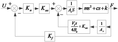
According to the road impact load simulation system shown in Fig. 3, a control block diagram of the simulation system can be drawn, as shown in Fig. 4. The input control command is , the hydraulic output loading force is , the amplifier gain is , the electro-hydraulic servo valve gain is , the hydraulic cylinder effective area and volume are , , the hydraulic cylinder leakage coefficient is , the hydraulic elastic modulus is , the pressure sensor gain is , the mass of the sliding rail moving parts is , the damping coefficient and elastic coefficient of the tire are , .
Fig. 3Structure diagram of pavement impact load simulation system
According to the system control (see Fig. 4), the open-loop transfer function of the system can be derived, as shown in Eq. (1):
It can be seen from Eq. (1) that the open-loop gain of the system includes the electro-hydraulic servo valve gain, and this electro-hydraulic servo valve gain is large generally. Therefore, the open-loop transfer function of the electro-hydraulic servo loading system is a high-gain system, and its molecular part contains an oscillation link, which has poor stability and needs to be corrected during the re-control process. It is difficult to achieve satisfactory control effect by using the conventional PID control method. If the control gain is too large, it will easily cause oscillation, and if the control gain is too small, it will be difficult to ensure the control accuracy[13]. Therefore, this paper adopts the load control strategy of iterative learning control to achieve high-precision dynamic loading of road loads.
Fig. 4Control block diagram of impact load simulation system
5. Iterative learning control method
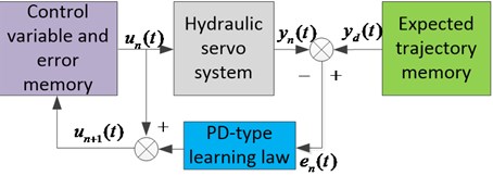
Iterative learning control (ILC) is a commonly used intelligent control method to effectively solve nonlinear control. It is favored by researchers because ILC can completely track the ideal output of the control system. As shown in Fig. 5, the basic principle of iterative learning is to use the error in the last control cycle, (), to correct the control input in the next control cycle (). After multiple operating cycles, the actual output of the system, (), converges to the ideal output.
Fig. 5Structure Diagram of PD iterative learning control system
Suppose that a nonlinear discrete system is:
The general algorithm of the first-order PID iterative learning control is shown in Eq. (3), , , and are proportional, differential, and integral coefficients respectively. is the control error of the -th iteration. There are many simplified forms of Eq. (3), such as P-type iterative learning algorithm, D-type iterative learning algorithm, PI-type iterative learning algorithm, and PD-type iterative learning algorithm:
According to the requirements of high-frequency and high-precision of road loads, PD-type iterative learning control algorithm shown in Eq. (4) is adopted in this paper. Compared with Eq. (3), the integral term is simplified to ensure the stability of iteration:
At this time, the nonlinear discrete-time system Eq. (2) at the -th iteration runtime is expressed as:
The system output error is: , and the corresponding learning law is:
If the partial derivative of , on , exists, then , , and , meet the Lipschitz condition, so:
6. Analysis of test results
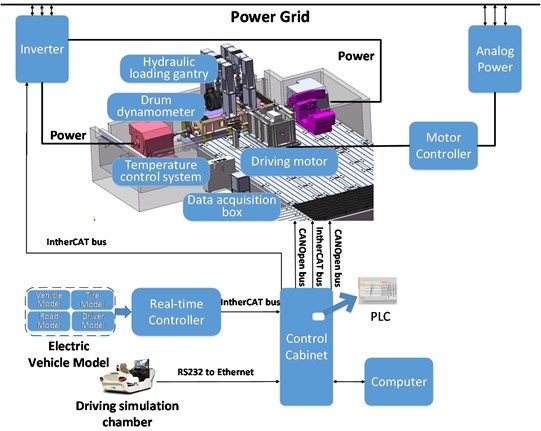
Fig. 6 contains a control diagram of the vehicle driveline road load simulation system. The output end of the driveline axle of the tested vehicle is driven by the asynchronous motor with 48-inch drum to simulate and load the longitudinal driving resistance of the vehicle. The input end of the transmission is connected to an AC asynchronous motor to simulate the driving speed or torque provided by engine or driving motor. At the same time, the input and output ends of the tested drivetrain are respectively connected to the speed and torque sensors to collect the feedback signals. The speed closed-loop feedback signals of the two motors are obtained by the encoder installed on the electric machine. The communication between the upper computer, real-time controller and motor driver adopts the industrial standard EtherCAT bus protocol, with the transmission capacity of 200Mbaud (full duplex) and the sampling frequency up to 20 kHz. In the test bench control system, the host PC selects the Master mode, and the real-time controller selects the Slave mode. RS232 to Ethernet mode is used for sampling to transmit driving simulation cabin information with low response requirements. The communication sampling CANopen protocol between real-time controller and hydraulic servo system is a standard fieldbus protocol of industrial control system, with the highest communication baud rate up to 1 Mbps.
Fig. 6Schematic diagram of road load simulation system control for vehicle drivetrain system
Figs. 7-8 show the comparison between the iterative learning control method of hydraulic servo simulation system after 10 iterations and the conventional PID control method. It can be seen from the enlarged figure in Fig. 8 that the conventional PID control curve obviously has a large overshoot. Compared with the given target curve, the iterative learning control error is 4.8 %, the conventional PID control error is 7.1 %. The tracking accuracy of the iterative learning control method is better than that of the conventional PID control method. From Fig. 9, the maximum tracking error of the simulation system after 3 times of learning is 17.3 %. Now the tracking error is large but after 10 times of learning, the tracking error is 4.8 %. At this time, the accuracy requirements of road simulation within 5 % have been met.
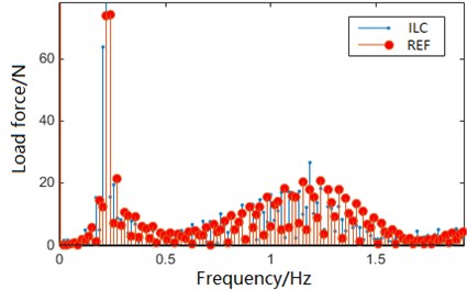
Figs. 10-11 show the comparison between the frequency domain amplitude of the sliding mode after 10 iterations and the frequency domain amplitude of the reference curve. The amplitude difference of the low-frequency part is very small, and the amplitude error of the frequency part is large. This occurs due to the system inertia, and the responses of the controllers are all slow relatively.
Fig. 7Comparison between iterative learning control after 10 iterations and PID control
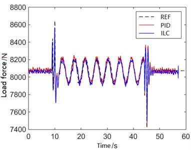
Fig. 8Comparison between iterative learning control after 10 iterations and PID control (magnification figure)
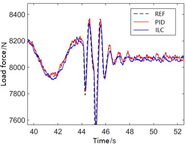
Fig. 9Tracking error of iterative learning control
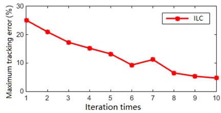
Fig. 10Frequency content of iterative learning control after 10 iterations
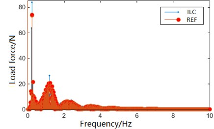
Fig. 11Frequency content of iterative learning control after 10 iterations (magnification figure)
7. Conclusions
The road load simulation test system for the vehicle drivetrain is used to reproduce the vehicle’s longitudinal driving load on the real road, and the vertical impact load caused by the bumpy road in the laboratory. In order to simulate more realistically the operating conditions of the drivetrain during the driving process of the vehicle and improve the tracking accuracy of the control system to the target load curve in the process of road impact load simulation, the following work is done in this paper:
1) The road load simulation test system for the vehicle drivetrain based on the drum dynamometer and the hydraulic load system are established. The drum dynamometer is used to simulate the longitudinal driving load resistance of the vehicle, and the hydraulic loading mechanism is used to simulate the change of the vertical load on the transmission system when the vehicle passes through the bumpy road, so as to achieve a more realistic simulation of the operating state of the transmission system when driving a vehicle.
2) An iterative learning control method is designed. Iterative learning control reduces the tracking error by performing the same task repeatedly, making the system output close to the ideal value as much as possible. Furthermore, the iterative learning control avoids the instability caused by the system oscillation in the process of conventional PID control.
3) After 10 times of learning, the control error of ILC (4.8 %) is 3.2 % higher than that of conventional PID control (7.1 %). The tracking accuracy of ILC method is better than the conventional PID control method. The load response error after iteration can be controlled within 5 %, which meets the requirements of indoor road simulation test.
In the future research, we will optimize the methodology for road simulation to increase control accuracy and convergence speed. Real road load data will be collected and processed to be reproduced on the test bench. At the same time, we will compare the test results on the test bench and on vehicle testing ground.
References
-
Cornelis B., Toso A., Verpoest W., Peeters B. Improved MIMO FRF estimation and model updating for robust Time Waveform Replication on durability test rigs. 26th International Conference on Noise and Vibration Engineering, Vol. 1, 2014, p. 759-774.
-
Reza Serajian, Saeed Mohammadi, Asghar Nasr Influence of train length on in-train longitudinal forces during brake application. Vehicle System Dynamics, Vol. 57, Issue 2, 2019, p. 192-206.
-
Wang Lichen, Zang Mengyan, Yang Xiaoguang, et al. Simulation of transient dynamic characteristics of radial tire on uneven. Chinese Journal of Automotive Engineering, Vol. 8, Issue 5, 2018, p. 339-343.
-
Dodds C. J., Plummer A. R. Laboratory road simulation for full vehicle testing a review. Proceedings of the Symposiumon International Automotive Technology, 2001.
-
Ed Habtour, Connon William Skip, Pohland Michael F., et al. Review of response and damage of linear and nonlinear systems under multiaxial vibration. Shock and Vibration, Vol. 2014, 2014, p. 294271.
-
Moten S., Pipeleers G., Desmet W., Swevers J. A combined use of the adaptive inverse plant modeling and iterative learning control strategy for service load simulations. 5th Australian Control Conference (AUCC), Gold Coast, 2015, p. 277-282.
-
Müller T., Endisch C. Compensation techniques for iterative rig control in multi-axial durability testing. IEEE 21st International Conference on Emerging Technologies and Factory Automation (ETFA), Berlin, 2016.
-
Ufuk Dursun, Cansever G., Üstoğlu İ. Neuro-fuzzy iterative learning control for 4-poster test rig. Transactions of the Institute of Measurement and Control, 2020, https://doi.org/10.1177/0142331220909597.
-
Mohammadi M., Eskola R., Mikkola A. Constructing a virtual environment for multibody simulation software using photogrammetry. Applied Sciences, Vol. 10, Issue 12, 2020, p. 4079.
-
Kostrzewski M. Sensitivity analysis of selected parameters in the order picking process simulation model, with randomly generated orders. Entropy, Vol. 22, Issue 4, 2020, p. 423.
-
Koch U., Wiedemann D., Ulbrich H. Model-based MIMO state-space control of car vibration test rig with four electromagnetic actuators for tracking of road measurements. IEEE Transactions on Industrial Electronics, Vol. 58, Issue 12, 2011, p. 5319-5323.
-
Wang X., Cong D., Yang Z., Xu S., Han J. Modified quasi-newton optimization algorithm-based iterative learning control for multi-axial road durability test rig. IEEE Access, Vol. 7, 2019, p. 31286-31296.
-
Wang Shoukun, Wang Junzheng, Zhao Jiangbo, et al. Fatigue test method of compound insulator based on electric-hydraulic proportional-servo loading technology and iterative learning control. Journal of Mechanical Engineering, Vol. 49, Issue 22, 2013, p. 192-198.
-
Zeigler B. P., Muzy Alexandre, Kofman Ernesto Theory of Modeling and Simulation. 3th ed., Academic Press, New York, 2019, p. 674.
-
Feilong Liu, Amaratunga Gehan A. J., Collings Nick, Soliman Ahmed Experimental study on engine dynamics model based in-cylinder pressure estimation. SAE Technical Paper 2012-01-0896, 2012, https://doi.org/10.4271/2012-01-0896.
-
Singh M., Mohanty K. B., Member S., et al. Sliding mode control of feedback linearized induction motor using TS fuzzy based adaptive iterative learning controller. 9th IEEE International Conference on Power Electronics and Drive Systems, Singapore, 2011.
-
Saravanakumar G., Wahidha Banu R. S. D., Nayak C. G. Design of modified dead-time compensators for stable process with integrator and longer time using adaptive control. International Conference on Intelligent and Advanced Systems, 2007.
About this article

This project is supported by the National Key R&D Program of China (Grant No. 2018YFB0105402) and National Natural Science Foundation of China (Grant No. 51805061).
