Abstract
In order to improve the ride comfort of the cab of construction machinery and reduce the harm of vibration to the driver, the lumped parameter model of passive hydraulic damping rubber mount (PHDRM) considering the nonlinearity of multi-inertial tracks is first established. Then the overall FE (finite element) fluid-solid coupling model of the vibration isolator is proposed by using ABAQUS combined simulation mode in this paper. Meanwhile, Combined with bidirectional strong coupling algorithm, the parameters of the rubber main spring and inertial track are identified respectively. Also, the dynamic characteristic experiments of the PHDRM samples are carried out. The experiment results show that the analytical solution and FE modeling method of the HDRM system are reliable and accurate under larger amplitude excitation. On the basis of this, the effects of the rubber main spring and inertial track of PHDRM on low frequency dynamic characteristics under larger amplitude excitation are respectively analyzed and discussed. It provides practical reference value for nonlinear modeling method research and dynaimc performance analysis of PHDRM with complex structure further.
1. Introduction
In the recent years, as modern construction and transportation equipment, the construction machinery, such as loader, earthmover, etc., has had a profound impact on various fields of national economic construction and developed rapidly. The idea of “people-oriented” has been paid attention more and more, especially the cab will be subjected to different levels of excitations from the road surface during the operation of construction machinery [1-3]. If the driver has been always in the forced vibration working environment for a long time, it will cause high fatigue [4, 5] and lead to frequent accidents, and the driver's health will be seriously damaged. However, the traditional research mainly focuses on the vibration isolation of engines and vehicle mounted equipment [6-8], and the driver's physical feelings are ignored. Therefore, the research and design of cab suspension system has been highly valued by all walks of life year by year. Improving the bad working environment of drivers is an important development direction of cab suspension system of construction machinery.
Related studies have shown that the human body is a complex resonance system, especially sensitive to low frequency vibration [9-13]. When the vibration and shock caused by various excitations of road surface and engine are transmitted to the cab through the frame, it will cause complex vibration coupling characteristics. In order to improve the vibration of the cab, many studies are devoted to the design of semi-active vibration isolators. However, for large heavy-duty construction machinery, the manufacturing cost of vehicles has been greatly increased. The passive hydraulic damping rubber mount (PHDRM) has remarkable nonlinear characteristics, and its stiffness and damping characteristics are obviously superior to those of the traditional rubber or spring vibration isolators [14, 15]. It is a kind of vibration absorber with excellent performance, which is more used in construction machinery cab suspension system. At present, there is still a lack of research on the nonlinear modeling method of PHDRM, and its complex flow-solid coupling mechanical properties are the key research contents for reducing cab vibration. According to the literature [16], the experimental research and the parameter identification are respectively carried out for two kinds of hydraulic damping suspension with different shapes and sizes of orifice, and the dynamic characteristics of orificing disk hydraulic damping suspension are analyzed. Compared with the experimental results, the correctness of the mechanism of orificing disk is verified. A lumped parameter model for hydraulic damping suspension with multi-inertial channels is established in the literature [17] in order to analyze dynamic characteristics. The dynamic stiffness and the calculation method of its hysteresis angle are deduced, and the formula of peak frequency of hysteresis angle is also given. The literature [18] has studied the relationship between design parameters of a hydraulic suspension system and dynamic stiffness, hysteresis angle. And by parameter identification technique, the nonlinear lumped parameter model is established and the influences of fluid track on the dynamic characteristics of the system are analyzed. The results show that the simulation datum are consistent with the experimental results, and the parameter identification method is effective. However, from another perspective, the lumped parameter modeling method is used to establish the hydraulic damping suspension model, which cannot calculate the distribution of liquid flow in fluid track and pressures in different chamber of the vibration isolator. But the flow-solid coupling FE simulation analysis method can effectively avoid the above problems, and is widely used in engineering and has achieved good results. Many scholars have adopted the FE method in the structural design of hydraulic damping rubber mount. A nonlinear finite element model of rubber material of hydraulic damping suspension system is established in the literature [19]. The dynamic equivalent elastic modulus of elastic material is determined by iterative model updating program. The nonlinear FE model of hydraulic damping suspension is established by using INTESIM strong liquid- solid FE method in literature [20]. The static and dynamic stiffness characteristics of the vibration isolator are analyzed, and the validity of the simulation results is verified. Also, the literature [21] describes a two-dimensional fluid-solid coupling FE model for hydraulic damping rubber mount and static analysis and structural optimization have been carried out. By using nonlinear FE method, the performance parameters of PHDRM structure are identified in the literature [22] and the superplastic constitutive relation is used to accurately describe the incompressible properties of rubber materials, and then the dynamic behaviors of two different hydraulic damping suspensions are analyzed. However, in the existing studies, fewer reports have been found on the research and calculation of the overall FE modeling method for PHDRM. Therefore, it is necessary to establish an accurate simulation model of hydraulic damping suspension system for construction machinery cab, and the low frequency dynamic characteristics are analyzed according to the main parameters of the vibration isolator.
In this paper, the low frequency dynamic characteristics of passive hydraulic damping rubber mount under larger amplitude excitation are examined. A lumped parameter model of passive hydraulic damping rubber mount considering the nonlinearity of multi-inertial tracks is proposed in the following section. Then, the overall FE fluid-solid coupling model of the vibration isolator is developed. Meanwhile, based on the established FSI (Fluid-structure-Interaction) models of rubber main spring and inertial track, the main parameters are respectively identified. The identified results are applied to the nonlinear lumped parameter model with multi-inertial tracks above. Moreover, the low frequency larger amplitude excitation experiments of the PHDRM samples are investigated, while validating good agreement with the above simulation results. Finally, the influences of the rubber main spring and inertial track of PHDRM on low frequency dynamic characteristics under larger amplitude excitation are analyzed and discussed in detail.
2. Modeling of cab hydraulic damping suspension system
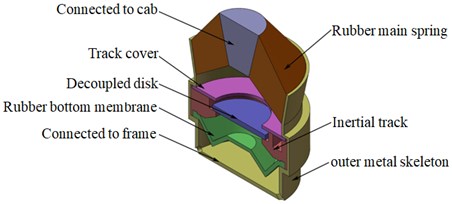
Due to strong vibration or shaking produced during operation for the cab of construction machinery, it is very difficult to improve the bearing capacity of hydraulic damping rubber mount by redesigning the structural dimensions and weights of the cab, especially for medium and heavy construction machinery. Fig. 1 shows the 3D model diagram of the inertial track-decoupled disk hydraulic damping rubber mount, which consists of rubber main spring, inertial track, rubber bottom membrane, decoupled disk and outer metal skeleton, etc. When hydraulic damping rubber mount is working, the top of the vibration isolator is connected to the cab, and the bottom of the vibration isolator is connected to the frame, and the external vibration makes the liquid reciprocate quickly in the inertial track by the rubber spring. The secondary suspension system of construction machinery is widely considered to be mainly low frequency vibration isolation. In addition, the structures of vibration isolator internal components such as rubber spring and inertial channel are optimized, which greatly improves the bearing capacity of the vibration isolator and has the low frequency and large damping characteristics.
Fig. 1The 3D model of passive hydraulic damping rubber mount (after simplied)
2.1. Modeling of lumped parameters of hydraulic damping suspension system
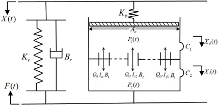
In order to analyze and compare the low frequency dynamic characteristics of hydraulic damping rubber mount, a lumped parameter model considering the nonlinearity of multiple inertial tracks is established, as shown in Fig. 2. The main parameters in the model include the dynamic stiffness of the rubber main spring, and equivalent viscous damping coefficient , which has very small influence on the dynamic characteristics of the vibration isolator by experiments and can be negligible in the low frequency range, and also the equivalent piston area , the volume stiffness of the upper liquid chamber , the volume stiffness of the lower liquid chamber , the inertia coefficient and the flow damping coefficient of the liquid flowing through the inertial track. The system variables in the lumped parameter model are respectively the average pressure of the upper liquid chamber and the lower liquid chamber and , the liquid rate of flow through the inertial track , the displacement excitation at the input end and the support reaction at the output end .
Fig. 2Lumped parameter model of hydraulic damping rubber mount considering the nonlinearity of multi-inertial tracks
When the external excitation frequency is low and the amplitude is large, the decoupling disk of hydraulic damping rubber mount is in the unstarted state in most of the time, thus it is approximate that the liquid flows only through the inertial track between the upper and lower liquid chambers. Considering that the inertia force and damping force of liquid flowing through inertial track are nonlinear, so the nonlinear momentum equation of liquid flow in inertial track can be derived as follows:
Due to the incompressibility of the liquid, the relationship between the motion velocity of the rubber main spring equivalent piston and the flow velocity of the liquid in the inertial track can be expressed as:
where, is the fluid displacement in the inertial track.
The continuity equation of liquid flow can be given as:
By substituting Eq. (2) and Eq. (3) into Eq. (1), the nonlinear momentum equation of liquid flow in inertial track is then given by:
where, is quadratic function of vibration velocity of rubber main spring equivalent piston, which can be linearized by methods in the literature [23]:
where, is the displacement amplitude of rubber main spring equivalent piston.
Thus, Eq. (4) is rewritten as:
The force equilibrium equation of the suspension system is establihsed as follows:
where, is the equivalent linear stiffness of the upper liquid chamber, .
The state equation of the system is established by nonlinear momentum equation and continuity equation of system:
where:
Letting , according to the above equations, by the Las transformation and substituting Eq. (8) into Eq. (7), the dynamic reaction force of the hydraulic damping rubber mount is obtained as follows:
Since the rubber bottom membrane is thin, , thus the complex stiffness of the isolation system is given by:
When , Eq. (7) can be considered as the theoretical formula of lumped parameter model with the single inertial track. The above lumped parameters are required to be identified further by the FEM method in the next Part. Then the identified results can be substituted into Eq. 10, and the low frequency dynamic characteristics of the hydraulic damping rubber mount can be obtained. The analytical results are shown in Fig. 15-16.
2.2. FE Modeling of hydraulic damping suspension system
The liquid in the passive hydraulic damping rubber mount will reciprocate between the upper chamber and lower chamber, and the interaction of fluid and solid exsits in the chamber of the vibration isolator. Therefore, based on fluid-solid coupling method, the overall finite element model of the hydraulic damping rubber mount is established by combined simulation mode in ABAQUS. Due to the small deformation of rubber main spring metal skeleton, it usually can be neglected. Because the rubber main spring is the typical superplastic material, the deformation characteristics within 80 % of rubber can be better described by using the Mooney-Rivilin material model in ABAQUS, which also has good stability. The strain energy function of the Mooney-Rivilin material model can be expressed as follows:
When 1, the strain energy function of second order Mooney-Rivilin material model can be given by:
where, , and are respectively the temperature-related material parameters, and are first and second order strain invariant, respectively. is the elastic volume ratio, and assuming that the rubber material is isotropic and incompressible, the influence of elastic volume ratio can be neglected. The parameters of rubber material are shown in Table 1. Other structures are set to be steel materials.
Table 1The parameters of rubber material
Rubber density | Superelasticity | ||
(Kg/m3) | C10 | C01 | D1 |
0.97×10⁻⁹ | 0.44 | 0.11 | 0.001 |
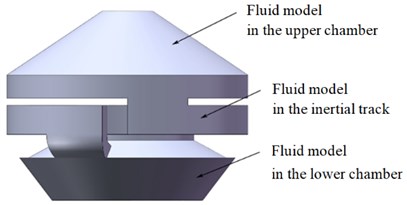
In the simulation environment, the assembly position of the fluid model and the solid model in the same coordinate system should be guaranteed to match each other. Therefore, the fluid model of simplified vibration isolator is shown in Fig. 2, which is divided into three parts: the fluid model in the upper chamber, the fluid model in the inertial track, and the fluid model in the lower chamber. Table 2 shows the material parameters of the fluid finite element model. Then, the overall FE modeling of hydraulic damping rubber mount is carried out by ABAQUS. First, the FE models of solid and fluid are respectively established, which can be discretized using different element and mesh sizes. Secondly, the flow-solid coupling interface is defined as follows: (1) the contact surfaces between the fluid in the upper chamber and rubber main spring, metal skeleton and track cover, (2) the contact surfaces between the fluid in the lower chamber and rubber bottom membrane, track cover, (3) the contact surfaces between the fluid in the inertial track and track cover. Each pair of flow-solid coupling surfaces are respectively selected in the solid model and the fluid model. In order to make the FE mesh size of the fluid model and the solid model basically consistent and improve the calculation efficiency, each pair of contact surfaces in the fluid and the solid model should be created with the same area during the pretreatment process. When the location of the fluid and solid nodes on the flow-solid coupling surface can not be coincided, the displacement of the fluid node is obtained by the displacement interpolation of the solid node, and the stress of the solid node is obtained by the pressure interpolation of the corresponding fluid node. The information on the structural materials and FE unit nodes of each part of hydraulic damping rubber mount are shown in Table 3.
Table 2The parameters of fuild material
Density of Silicone oil / T·(mm3)-1 | Dynamic viscosity / MPa·s |
1.1×10⁻⁹ | 5.6×10⁻⁸ |
Table 3Information on the structural materials and FE unit nodes of hydraulic damping rubber mount
Structure | Material | Unit length | Unit type | Number of units | Number of nodes |
Rubber main spring | Rubber | 6 | Tetrahedron | 22364 | 11327 |
Inertial track | Steel 45 | 8 | Tetrahedron | 13791 | 3865 |
Rubber bottom membrane | Rubber | 6 | Hexahedron | 3662 | 4201 |
Liquid | Silicone oil | 4 | Hexahedron | 83694 | 15712 |
Decoupled disk | Steel 45 | 8 | Tetrahedron | 4938 | 4010 |
Track cover | Steel 45 | 8 | Tetrahedron | 2941 | 1085 |
Because of the incompressibility of the fluid in the hydraulic damping rubber mount, thus the combined simulation mode in ABAQUS should be created to carry out the fluid-solid coupling calculation. When modeling, the dynamic analysis module and fluid dynamics analysis module are combined with each other together. The solid FE model is applied in the ABAQUS/Explicit Model and the fluid FE model is applied in the ABAQUS/CFD Model. By discretizing the dynamic equations of fluid and solid and introducing coupling boundary conditions, the nonlinear FE equation of fluid-solid coupling system can be yielded:
where, and are respectively the FE equations corresponding to the equations of motion of fluid and solid, , is the vector consisting of the velocity vector of nodes in the fluid FE model and the pressure vectors of the elements, is the vector composed of displacement vectors of nodes in the solid FE model, and are respectively the displacements of the structures and the stresses of the fluid on the coupling boundary.
Fig. 3Schematic diagram of fluid model
3. Parameter identification of hydraulic damping suspension system
3.1. Parameter identification of rubber main spring
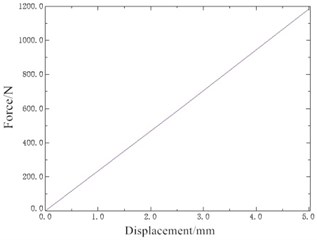
The FE mesh of rubber main spring is built by using ten node quadratic tetrahedron elements C3D10H, and the displacement load of 5 mm is carried out. The displacement cloud map of the rubber main spring is obtained, as shown in Fig. 4. The total reaction force can be obtained by extracting support reaction of all the nodes subjected to the displacement load at the top of the vibration isolator. By using the total reaction force and the displacement as the horizontal and vertical coordinates respectively, the force-displacement curve of the rubber main spring is obtained as shown in Fig. 5. Thus, the static stiffness of the rubber main spring in the vertical direction is calculated as 236.71 N/mm, and its dynamic stiffness can be estimated by the following formula:
Normally, when 1.4, the dynamic stiffness is calculated as 331.39 N/mm.
Fig. 4Displacement cloud map of rubber main spring
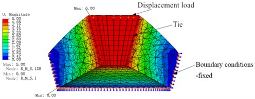
Fig. 5Force-displacement curve of rubber main spring
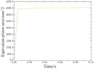
When the rubber main spring produces displacement under preload, the fluid model in the upper chamber is added into the rubber spring solid model. By using the combined simulation mode, a pressure “head” is set for the fluid and the fluid will flow down the bottom surface under pressure. So the bottom pressure of the fluid is set to 0 MPa, which makes the fluid flows down. Also, experiments show that when the excitation displacement exceeds 3 mm, the equivalent piston area of the rubber main spring is basically unchanged and independent on the excitation frequency. Fig. 6 shows the displacement cloud map of the fluid model in the fluid-solid coupled model, from which the values of the displacement of fluid downward , the area of fluid bottom , and the upper end displacement of solid can be obtained respectively. According to Eq. (15):
the equivalent piston area of rubber main spring is obtained 4035 mm2. Fig. 7 shows that the equivalent piston area of rubber main spring after stable motion is about 4008.48 mm2. The volume stiffness of upper liquid chamber is written as:
where, is the variable quantity of fluid pressure for inner chamber of rubber main spring, is the variable quantity of volume in the inner chamber. By loading displacement, the FSI model of rubber main spring can be solved to obtain the volume stiffness of the upper liquid chamber 4.21×10¹⁰ N/m5.
Fig. 6Displacement cloud map of the fluid model (FSI)
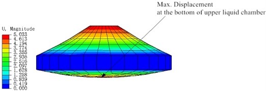
Fig. 7Equivalent piston area curve over time
3.2. Parameter identification of inertial track
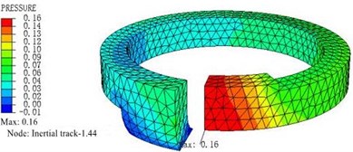
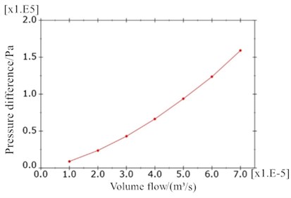
The fluid FE model in the inertial track is meshed with tetrahedron element FC3D4. The inlet cross section of the inertial track is set to the velocity load surface, and the outlet cross section pressure is set to 0 MPa, and the other surfaces are set to the fluid wall. The velocities of fluid inflow are respectively given as 682 mm/s, 1364 mm/s, 2046 mm/s, 2728 mm/s, 3410 mm/s, 4093 mm/s, 4775 mm/s. Fig. 8 shows the pressure distribution cloud map and velocity cloud map of inertial track at inlet fluid velocity of 4775 mm/s by simulation and analysis. The relationship curve between pressure difference and cross section flow at each flow rate is shown in Fig. 9. The momentum equation is given by:
where:
and represent the pressure difference and flow rate between the inlet and outlet of the inertial track respectively, and by MATLAB calculation the flow damping coefficient of inertial track can be obtained as 1.1×10⁸N⋅s/m5. The inertia coefficient of liquid flowing through inertial track is given as = 2.58×10⁶ kg/m4, the cross section area for inertial track is given as 80 mm2, and the length of inertial track is given as 102.6 mm.
Fig. 8Simulation of inertial track at inlet fluid velocity of 4775 mm/s
a) Pressure distribution diagram
b) Flow rate diagram
Fig. 9Relationship curve of flow and pressure difference in inertial track
4. Analysis of dynamic performance of hydraulic damping suspension system
4.1. Dynamic characteristic analysis of flow-solid coupling
The main dynamic characteristics of passive hydraulic damping rubber mount include dynamic stiffness and hysteretic angle, which can be obtained by dynamic reaction-displacement curve of hydraulic damping suspension system during one vibration period.
The equation of dynamic stiffness, hysteretic angle and damping coefficient are respectively as follows:
where, are are the force and displacement amplitudes, respectively, and is the area of hysteresis loop.
For the simulation of dynamic characteristics, the vertical displacement load is first applied on the top surface of the rubber main spring:
where, is the preload displacement for hydraulic damping suspension system, relating to the static working load of the vibration isolator, is the dynamic displacement excitation amplitude, is the excitation frequency. By using ABAQUS multi-field coupling solution platform, the collaborative analysis task can be created based on Dell workstation with ZQ E5-2665 2.40 GHz 8-core processor. Then, the curve of the displacement of the active end of rubber main spring and dynamic reaction force is obtained, as shown in Fig. 10(a). It can be seen that there is hysteresis in the relationship between dynamic reaction force and displacement, which indicates that the suspension system has a larger damping hysteretic angle. Compared with Fig. 10(b), it is found that the hysteresis produced at 10 Hz is slightly larger than that at 20 Hz, and the damping hysteresis angle of the system is smaller at 20 Hz excitation frequencies.
Fig. 10The hysteretic curves of rubber main spring and dynamic reaction force for hydraulic damping suspension system
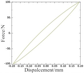
a)0.05 mm, 0.2 mm, 10 Hz
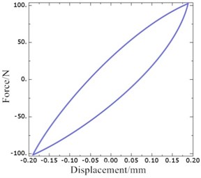
b)0.05 mm, 0.2 mm, 20 Hz
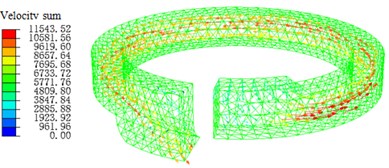
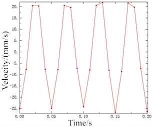
The motion states and deformations of the fluid at any time during the whole excitation process can be observed by the visual results of nonlinear FE calculation. Fig. 11 shows the pressure distribution cloud diagram of the fluid. It can be seen that there is obvious pressure gradient in inertial track at different times in one cycle, and the pressure distributions of the upper and lower liquid chambers are basically uniform. When 0.15 s, the fluid pressure of the upper and lower liquid chambers changes obviously. The liquid flows between the upper and lower chambers through the inertial track, and the pressures at the inlet and outlet of the inertial track changes with the reciprocating motion of the fluid. The maximum flow velocity is 1472 mm/s, as shown in Fig. 12. Fig. 13 shows the load velocity curve applied to the top surface of the rubber main spring. It indicates that the maximum velocity is 26.84 mm/s. Thus, the ratio of the two velocities is about 54.84, which is not different from the ratio of the equivalent piston area of the rubber main spring to the cross section area of the inertial track. The correctness of the FE model can be verified.
Fig. 11The pressure distribution diagrams of Fluid Model at different Times (A= 0.2 mm, f= 10 Hz)
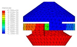
a)0.11 s
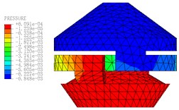
b)0.14 s
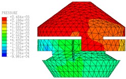
c)0.15 s
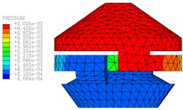
d) 0.16 s
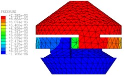
e)0.17 s
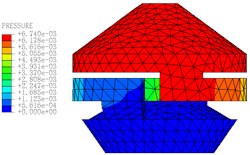
f)0.18 s
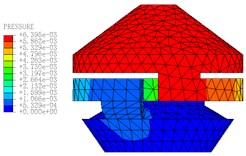
g)0.19 s
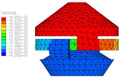
h)0.20 s
Fig. 12The velocity of flow distribution in inertial track (t= 0.15 s)
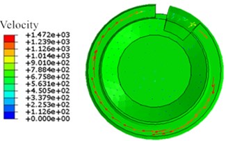
Fig. 13Load velocity curve under displacement excitation
4.2. Experiment verification
In order to further verify the effectiveness of lumped parameter modeling and overall FEM modeling, the dynamic performance experiments of the samples of passive hydraulic damping rubber mount were carried out. By using the MTS elastomer test platform, the working end of the test platform is connected with the connecting end of the bottom plate of the cab, and the vibration isolator is fixed on the test platform, as shown in Fig. 14. According to the total mass of the cab, the steady-state harmonic displacement excitation with the amplitude of 0.2 mm is first employed, and the preload displacement is 4 mm, and the excitation frequency range is 0-50 Hz. The displacement signal at the working end of the test platform and the reaction signal of the base of the vibration isolator are respectively recorded. According to Eqs. (18-20), the experimental datum cane be processed. Finally, the experimental results are shown in Fig. 15. It indicates that under the low frequency excitation, the dynamic characteristic curves of the hydraulic damping rubber mount by lumped parameter modeling and overall FEM modeling have good consistency with the experimental results, respectively, which illustrates above modeling methods are credible. Also, it can be found that there are still some deviations between the analytical solution of the dynamic characteristics and the nonlinear FE solution.
When the construction machinery is subjected by the road excitation with low frequency and large amplitude, the secondary suspension system of its cab will also be excited by the larger amplitude. Therefore, the larger amplitude excitation experiment of the vibration isolator is conducted. Fig. 16 shows the dynamic characteristics of hydraulic damping rubber mount under larger amplitude excitation. It illustrates the above two modeling methods still have reliability.
Fig. 14Mechanical performance test platform of vibration isolator
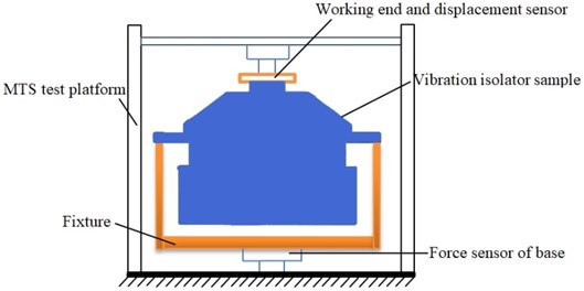
a) Schematic illustration of the vibration isolation clamping
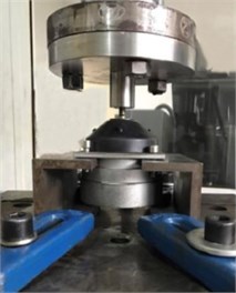
b) Test site
Fig. 15Dynamic Characteristics of hydraulic damping rubber mount when A= 0.2 mm
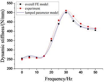
a) Dynamic stiffness
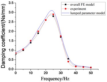
b) Damping coefficient
Fig. 16Dynamic characteristics of hydraulic damping rubber mount when A= 2.0 mm
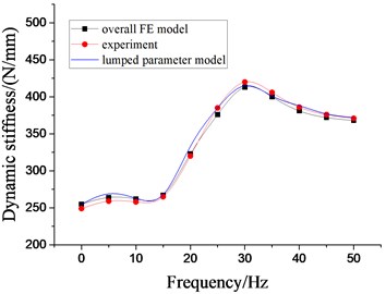
a) Dynamic stiffness
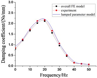
b) Damping coefficient
4.3. Effect of rubber main spring on low frequency dynamic characteristics under larger amplitude excitation
To deeply analyze the effects of rubber spring on the low frequency dynamic characteristics on the vibration isolator under larger amplitude excitation, the simulation analysis with setting frequency 5-50 Hz, 5 Hz per interval, 2.0 mm are carried out based on above fluid-solid coupling model. And the dynamic stiffness characteristics and damping coefficient at each excitation frequency are obtained, as shown in Fig. 17-18. The peak values of dynamic stiffness of hydraulic damping suspension have reached the maximum near 30 Hz, and then have decreased gradually, and also have increased with the increase of dynamic stiffness and equivalent piston area of rubber main spring. At the excitation frequency of 22 Hz, the damping coefficient of the vibration isolator reaches the peak, and then tends to decrease gently. Because of the poor working and transportation environment of construction machinery, hydraulic damping rubber mount can produce better vibration isolation effect with the inhibition of strong vibration or shaking of cab under larger amplitude excitation.
Fig. 17Effect of different dynamic stiffness of rubber main springs on dynamic characteristics of hydraulic damping rubber mount
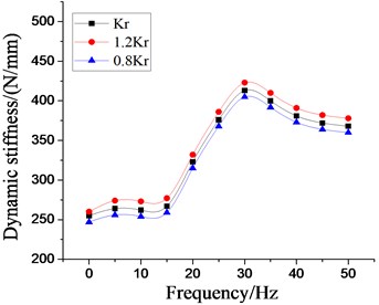
Fig. 18Effect of different equivalent piston areas on dynamic characteristics of hydraulic damping rubber mount
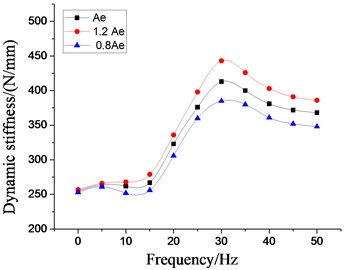
a) Dynamic stiffness
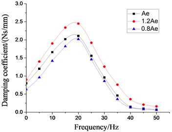
b) Damping coefficient
4.4. Effect of inertial track on low frequency dynamic characteristics under larger amplitude excitation
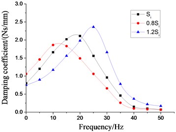
In order to analyze the influence of the physical parameters of the inertial track on the low frequency larger amplitude dynamic characteristics of the vibration isolator, the four most important factors, namely, the cross section area of inertial track, the length of inertial track, the number of inertial track, and the damping coefficient of inertial track flow, are respectively changed on the basis of the original model. Multiple groups of the dynamic stiffness and damping coefficient curves at different excitation frequencies are obtained by the above modeling method, as shown in Figs. 19-22, respectively. It can be seen that the peak values of dynamic stiffness of the hydraulic damping rubber mount have become larger with the increase of the cross section area and the number of the inertial track, while the peak variations of damping coefficient have shown the opposite result, and the peak frequencies of the damping coefficients have been gradually increasing with the increase of the number of inertial tracks. Therefore, in the structural design of the vibration isolator, the influence of the number of inertial tracks on the low frequency dynamic characteristics and the manufacturing cost should be considered synthetically. When the length of inertial track has increased gradually, the peak values of dynamic stiffness of the vibration isolator have first increased, and then decreased, and its peak frequencies has been decreasing. The results illustrates that the length of inertial track in a certain range will change the low frequency dynamic characteristics of hydraulic damping rubber mount under larger amplitude excitation. If the length value is too large, the stiffness will be small and the vibration isolation performance will become poor although its peak frequencies will be reduced. Since the sensitive frequency range of human body is 0.5-80 Hz according to ISO-2631, the driver's ride comfort should be considered fully for the vibration isolation performance of the cab hydraulic suspension system. If the length of the inertial track is slightly small, it would cause the peak frequency to be too large. Low frequency vibration isolation performance will also be reduced, especially under larger amplitude excitation. Meanwhile, the peak values of damping coefficient of the vibration isolation have gradually increased with the increase of length, and the peak frequencies have decreased continuously.
Fig. 19Effect of different cross section areas of inertial tracks on dynamic characteristics of hydraulic damping rubber mount
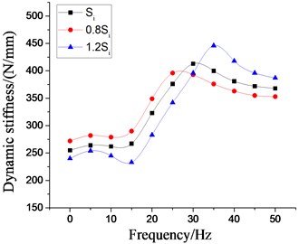
a) Dynamic stiffness
b) Damping coefficient
Fig. 20Effect of different number of inertial tracks on dynamic characteristics of hydraulic damping rubber mount
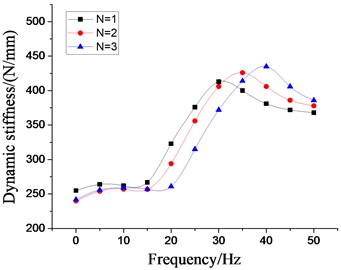
a) Dynamic stiffness
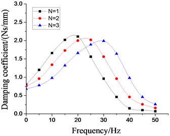
b) Damping coefficient
Fig. 21Effect of different length of inertial tracks on dynamic characteristics of hydraulic damping rubber mount
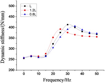
a) Dynamic stiffness
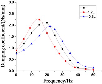
b) Damping coefficient
Fig. 22Effect of different damping coefficients of inertial tracks on dynamic characteristics of hydraulic damping rubber mount
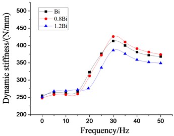
a) Dynamic stiffness
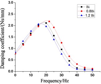
b) Damping coefficient
Moreover, It can be found from Fig. 22 that when the damping coefficient of the inertial track has been changed, the overall variation amount of the dynamic stiffness and damping coefficient curve of the vibraiton isolator under the low frequency larger amplitude is not very large. And the peak values of the dynamic stiffness, the peak values of the damping coefficients and their peak frequencies have been all decreased with the increase of the damping coefficient of the inertial track. Therefore, when the liquid viscosity of hydraulic damping rubber mount is selected, if the viscosity is smaller, it can not produce obvious damping effect when flowing through the inertial track, which affects the stiffness of hydraulic damping suspension system and reduces the vibration isolation performance. But if the viscosity is larger, However, if the viscosity is larger, it will also hinder the movement of fluid, or block the inertial track, which can not play a good vibration isolation effect.
5. Conclusions
In this work, the modeling method and nonlinear dynamic characteristic analysis for PHDRM of construction machinery cab are studied. Considering the nonlinearity of multi-inertial tracks, the nonlinear lumped parameter model of PHDRM is developed to predict the suspension system's low frequency dynamic characteristics under larger amplitude excitation. Meanwhile, an overall FE model of PHDRM with fluid-solid coupling is established, and the parameters of the rubber main spring and inertial track are identified respectively by using ABAQUS combined simulation mode. In addition, the experiment results of the PHDRM samples are in good agreement with the simulation results under low frequency larger amplitude excitation. Furthermore, the effects of the main parameters of PHDRM on low frequency dynamic characteristics under larger amplitude excitation are also respectively addressed. The analysis and discussion provide the analysis basis for the design and evaluation of the secondary suspension system of the construction machinery cab.
References
-
Kordestani A., Rakheja S., Marcotte P., et al. Analysis of ride vibration environment of soil compactors. SAE International Journal of Commercial Vehicles, Vol. 3, Issue 1, 2010, p. 259-272.
-
Yu Man, Zhou Chen Yu, Wei Lang, et al. Takagi-sugeno fuzzy-model-based automobile electrohydraulic active suspension H-infinity control. China Journal of Highway and Transport, Vol. 31, Issue 8, 2018, p. 205-217.
-
Sun X. J., Zhang J. Optimization of low-frequency vibration isolation for cab ride comfort of construction machineries. Journal of Mechanical Engineering, Vol. 21, 2012, p. 52-60.
-
Burstrom L., Aminoff A., Bjor B., et al. Musculoskeletal symptoms and exposure to whole-body vibration among open-pit mine workers in the Arctic. International Journal of Occupational Medicine and Environmental Health, Vol. 30, Issue 4, 2017, p. 553-564.
-
Liu C., Qiu Y., Griffin M. J., et al. Dynamic forces over the interface between a seated human body and a rigid seat during vertical whole-body vibration. Journal of Biomechanics, Vol. 61, 2017, p. 176-182.
-
Zeng X., Liette J., Noll S., et al. Analysis of motor vibration isolation system with focus on mount resonances for application to electric vehicles. SAE International Journal of Alternative Powertrains, Vol. 4, Issue 2, 2015, p. 370-377.
-
Zhang Hui Jie, Hao Hui Rong, Guo Zhi Ping Analysis and optimization design of six degrees of freedom engine mount system. Journal of Vibration Engineering, Vol. 32, Issue 5, 2019, p. 801-810.
-
Wang Min, Yao Guo Feng, et al. A novel design of semi-active hydraulic mount with wide-band tunable notch frequency. Journal of Sound and Vibration, Vol. 333, Issue 8, 2014, p. 2196-2211.
-
Deprez K., Moshou D., et al. Improvement of vibrational comfort on agricultural vehicles by passive and semi-active cabin suspensions. Computers and Electronics in Agriculture, Vol. 49, Issue 3, 2005, p. 431-440.
-
Morales A. L., Nieto A. J., et al. A semi-active vehicle suspension based on pneumatic springs and magnetorheological dampers. Journal of Vibration and Control, Vol. 24, Issue 4, 2018, p. 808-821.
-
Bovenzi M., Rui F., Negro C., et al. An epidemiological study of low back pain in professional drivers. Journal of Sound and Vibration, Vol. 298, Issue 3, 2006, p. 514-539.
-
Maciejewski I., Krzyzynski T., et al. Shaping the vibro-isolation properties of horizontal seat suspension. Journal of Low Frequency Noise Vibration and Active Control, Vol. 36, Issue 3, 2017, p. 203-213.
-
Ning Dong Hong, Sun Shuai Shuai, Du Hai Ping, et al. Integrated active and semi-active control for seat suspension of a heavy duty vehicle. Journal of intelligent material systems and structures, Vol. 29, Issue 1, 2018, p. 91-100.
-
De T. J., Deprez K., Anthonis J., et al. Conceptual cab suspension system for a self-propelled agricultural machine – part 2: operator comfort optimization. Biosystems Engineering, Vol. 90, Issue 3, 2005, p. 271-278.
-
Xu Pei Jun, Bill B., Ken T., et al. Optimal mounting design for cab vibration isolation. International Journal of Vehicle Design, Vol. 57, Issue 2, 2011, p. 292-304.
-
Fan Rang Lin, Lv Zhen Hua Nonlinear dynamic characteristics and parameters identification method for hydraulic engine mount. Journal of Mechanical Engineering, Vol. 43, Issue 7, 2007, p. 145-151.
-
Shangguan Wen Bin, Song Zhi Shun, Zhang Yun Qing, et al. Experimental study and simulation analysis of hydraulic engine mounts with multiple inertia tracks. Journal of Vibration Engineering, Vol. 18, Issue 3, 2005, p. 318-323.
-
Yang C., Yin Z., Shangguan W., et al. A study on the dynamic performance for hydraulically damped rubber bushings with multiple inertia tracks and orifices: parameter identification and modeling. Shock and Vibration, Vol. 2016, 2016, p. 3695950.
-
Jahani K., Dehnad M. Identifying the frequency dependent material property of a hydraulic engine mount through an iterative procedure using 3D finite element modeling. Journal of Mechanical Science and Technology, Vol. 28, Issue 6, 2014, p. 2041-2047.
-
Cao Zheng Lin, Li Jun, Guo Kong Hui, et al. Simulations of dynamic characteristics of hydraulic engine mounts by FEM with strong fluid-structure coupling. Journal of Vibration and Shock, Vol. 31, Issue 10, 2012, p. 4-8.
-
Sun X. J., Zhang J. Low-Frequency shaking of the construction machine cab and design of vibration isolators for protecting. Applied Mechanics and Materials, Vol. 141, 2011, p. 49-53.
-
Christopherson J., Jazar G. N. Dynamic behavior comparison of passive hydraulic engine mounts. Part 2: finite element analysis. Journal of Sound and Vibration, Vol. 290, Issue 3, 2006, p. 1071-1090.
-
Christopherson J., Nakhaie Jazar G. Dynamic behavior comparision of passive hydraulic engine mounts. Part 2: Finite element analysis. Journal of Sound and Vibration, Vol. 290, 2006, p. 1071-1090.
Cited by
About this article

This work has been funded by The National Natural Science Foundation of China (No. 11902207), the Natural Science Foundation of Hebei Province (A2020210018), Education and Teaching Reform Project of Shijiazhuang Tiedao University (Y2020-15).
