Abstract
In order to study the effect of the interaction between different inertial channels and decoupler membrane channels on the hydraulic mount characteristic. Firstly, the effect of the single inertia channel and decoupler membrane channel interaction on the hydraulic mount characteristic is analyzed. Secondly, a multi-inertia channel hydraulic mount model with nine structures and four combination schemes is proposed. Among them, the mount's structure includes long inertia channels, short inertia channels, different inertia channel cross-sectional areas, and the number of inertia channels. And then, the number of inertia channels, the cross-sectional area, and the interaction between long and short inertia channels and decoupler membrane channels are analyzed for their effects on the hydraulic mount characteristics. Finally, the effect of the interaction between the inertial and decoupler membrane channels on the time-domain characteristics of the hydraulic mount at different excitation amplitudes. The results show that the number of inertia channels, cross-sectional area, and the interaction between the number of long and short inertia channels and decoupler membrane channels directly affect the vibration isolation performance of hydraulic mounts at high and low frequencies.
Highlights
- Analyzes the characteristics of a combined single inertia channel and decoupler membrane hydraulic mount
- Proposes 9 different combinations of hydraulic mounts with different numbers of inertia channels, long and short inertia channels, and different cross-sectional area inertia channels
- Analysis of the effect of decoupler membrane channels interacting with combined 4 schemes of multiple inertia channels on hydraulic mount characteristics
1. Introduction
The engine mounts are vibration-isolating elements installed between the vehicle frame and the engine, which play an important role in improving the Noise, Vibration, and Harshness (NVH) of the vehicle. The desired properties of mounts require large stiffness and damping property under low-frequency large-amplitude excitation and small stiffness and damping under high-frequency small-amplitude excitation [1]. Among them, the inertial channel combined decoupler membrane structure is the most common hydraulic mount available. Singh [2] gives a linear mathematical model of the combined inertial channel and decoupler membrane hydraulic mount. Kim [3] identified the nonlinear characteristics of the inertia channel of the hydraulic mount based on the linear model proposed by Singh [2] to obtain the lumped parameter model of the hydraulic mount. Geisberger [4] obtained experimentally a nonlinear mathematical model of the combined inertial channel and decoupler membrane hydraulic mounts. Yoon [5, 6] proposed linear time-invariant, nonlinear and quasi-linear hydraulic mount models and used the models to predict the transfer forces of hydraulic mounts under sinusoidal excitation. Reference [7] shows that the single inertia channel hydraulic mount loss angle peak at 7-15 Hz cannot meet the engine mount wide frequency isolation. Based on the disadvantages of single inertia channel hydraulic mounts, scholars focus on the center of attention for multi-inertia channel hydraulic mounts or bushings for research. Zhang [8] studied the effect of the number, size, and length of inertia channels on the low-frequency dynamic performance of hydraulic mounts. Benjamin [9] experimentally analyzed the effect of the number of inertia channels on the dynamic characteristics of hydraulic mounts. Identification and mathematical modeling of the parameters of a multi-inertia channel hydraulic bushing system by an experimental approach by Yang [10]. Yang [11] analyzed the effect of different combinations of inertia channels or orifice flow paths on the low-frequency dynamic characteristics of hydraulic bushings. Tan Chai [12, 13, 14] for mathematical modeling of hydraulic bushings by different combinations of inertial channels and orifice flow paths; then, the effects of different inertia channels and orifice flow paths on the dynamic and time-domain characteristics of the hydraulic bushing are analyzed numerically and experimentally. Lu [15] derives a collective parametric model of the hydraulic bushing with the number of inertia channels equal to 2 and performs dynamic characterization. Li [16] proposed a hydraulic mounts model with different inertia channel and orifice flow path combinations, but this structure hydraulic mounts without considering the decoupler membrane channel. In summary, research on multi-inertia channel hydraulic mounts or multi-flow channel hydraulic bushings has focused on the effects of the number and structure of inertia channels on the characteristics of hydraulic mounts or hydraulic bushings. However, studies on the interaction of multi-inertial channels with decoupler membrane channels have not been reported.
To study the effect of different inertia channels and decoupler membrane interactions on the hydraulic mount characteristics. This paper first analyzes the characteristics of a combined single inertia channel and decoupler membrane hydraulic mount; Proposes 9 different combinations of hydraulic mounts with different numbers of inertia channels, long and short inertia channels, and different cross-sectional area inertia channels; Analysis of the effect of decoupler membrane channels interacting with combined 4 schemes of multiple inertia channels on hydraulic mount characteristics.
2. Hydraulic mount with decoupled membrane and inertia channel
2.1. Hydraulic mount high and low frequency characteristics
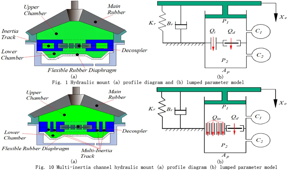
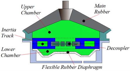
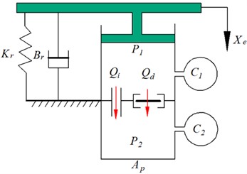
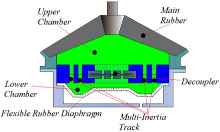
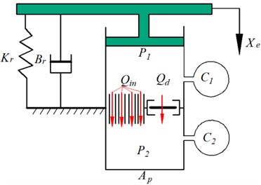
Fig. 1 shows a schematic diagram of the hydraulic mount, where Fig. 1(a) shows a profile diagram of the hydraulic mount, and Fig. 1(b) shows a lumped parameter model of the hydraulic mount. The engine mounts are supported by mainspring rubber elements that provide a certain amount of stiffness and damping to support the weight of the static engine, denoted by and , respectively; and are the volume flexibility of the upper and lower chamber; and are the upper and lower chamber pressures; the flow rate through the inertial channel; is the flow through the decoupler membrane channel. The narrow inertial channels and decoupler membrane channels provide large damping for the mounts as the fluid flows through the inertial channel and decoupled membrane channel when the mounts are subjected to external excitation .
Fig. 1Hydraulic mount a) profile diagram and b) lumped parameter model
a)
b)
According to Fig. 1(b), the mathematical model of the lumped parameters of the hydraulic mount can be solved by referring to the references [4, 16] as shown in Eqs. (1)-(5):
where is to better express the effective area variation of the decoupler membrane under different excitation amplitudes, and the specific solution is referred to the reference [4]:
where, and are the inertia and resistance of the fluid through the inertia channel, and and are the inertia and resistance of the fluid through the decoupler membrane channel. The first term and on the right side of Eq. (1) represent the pressure drop generated by the inertia coefficient of the fluid in the inertial channel and the decoupling membrane channel, respectively, and the second terms and represent the pressure drop generated by the viscous damping of the fluid in the inertial channel and the decoupler membrane channel, respectively. Where is the linear fluid resistance of the flow through the decoupler membrane channel, is the position of the decoupler plate, the decoupler membrane flow volume is denoted as , is the area of the decoupling plate, is the height of the decoupler cage, is used to produce a clear switching response, and is the nonlinear fluid resistance factor in the decoupler membrane. The values of the hydraulic mount parameters are shown in Table 1.
Table 1Hydraulic mount structure parameters
Symbol | Parameter | Value |
Effective piston area | 2.5×10⁻³ m2 | |
Upper chamber compliance | 3.0×10⁻¹¹ m5/N | |
Lower chamber compliance | 2.6×10⁻⁹ m5/N | |
Fluid inertia in decoupler | 7.5×10⁴ kg/m4 | |
Linear fluid resistance in decoupler | 1.17×10⁷ kg/(s⋅m4) | |
Upper chamber stiffness | 2.5×10⁵ m/N | |
Upper chamber damping | 100 Ns/m | |
Pressure normalized constant | 10 N/m2 | |
Flow normalized constant | 1.0×10⁻⁹ m3/s | |
Nonlinear resistance constant in decoupler | 1.0×10⁻⁴ kg/s⋅m4 | |
Half decoupler cage height | 5.3×10⁻⁴ m | |
Decoupler position control constant | 2.62×10⁻⁵ m | |
Decoupler switching function shape control constant | 1.0×10⁻⁹ m | |
Fluid density | 2660 kg/m3 | |
Fluid viscosity | 0.06 Pa⋅s | |
Inertia channel cross-sectional area | 57×10-3 m | |
Inertia channel length | 100×10-3 m |
The expression for the complex stiffness of the hydraulic mount can be obtained by combining Eqs. (1) to (5) in Eq. (6):
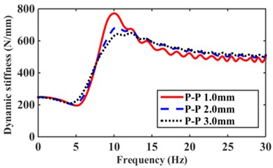
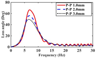
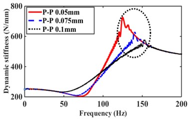
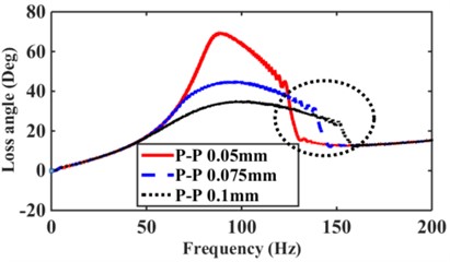
Low-frequency 0-30 Hz excitation amplitude numerical calculation can be obtained considering the nonlinear decoupled membrane hydraulic mount frequency response characteristics (dynamic stiffness and loss angle), as shown in Fig. 2(a), (b). we can observe strong amplitude and frequency nonlinearities in the dynamic stiffness and loss angles. Hydraulic mount’s initial values of dynamic stiffness and loss angle start from 250 N/m and 0 (Deg), respectively, and increase with frequency, then reach the intrinsic frequency and peak frequency of dynamic stiffness and loss angle, and then decrease slowly with the increase of excitation amplitude . Similarly, in the numerical calculation of the high-frequency 25-200 Hz, the excitation amplitude is 0.5, 0.075, 0.1 mm, respectively, as shown in Fig. 2(c), (d). Under high-frequency excitation, the hydraulic mounts exhibit dynamic characteristics similar to those of low frequency with strong amplitude and frequency nonlinearity. However, the hydraulic mounts show a “bending” frequency response at 100-150 Hz in the high-frequency region, which is due to the unstable region caused by the decoupled membrane nonlinearity, which is explained in detail in the literature [4].
Fig. 2Dynamic characteristics of hydraulic mount: a) low frequency excitation dynamic stiffness, b) low frequency excitation loss angle, c) high frequency excitation dynamic stiffness, d) high frequency excitation loss angle
a)
b)
c)
d)
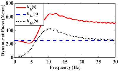
For the dynamic stiffness of the hydraulic mount, it can be decomposed into the contribution of the rubber path and the hydraulic path, which is expressed as follows:
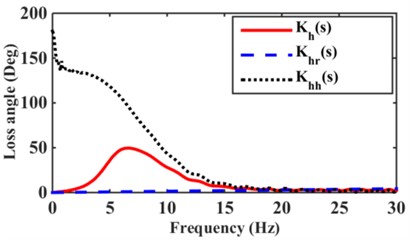
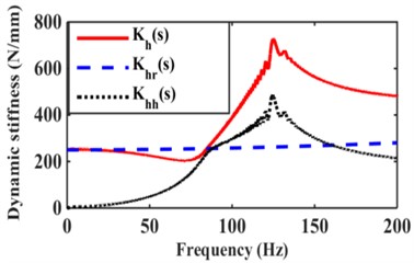
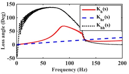
To analyze the variation of dynamic characteristics of the mounts with different excitation amplitudes. Numerical simulations of the variation of the mount dynamic stiffness and loss angle for the excitation amplitude 3.0 mm are shown in Fig. 3(a) and 0.05 mm in Fig. 3(b). From Fig. 3(a), (b), it can be seen that the dynamic stiffness of hydraulic mounts below 5Hz is mainly controlled by the rubber part, and the 5-20 Hz hydraulic mounts are controlled by the hydraulic part. However, the role of the hydraulic part is significantly reduced in 20 Hz-30 Hz. The dynamic stiffness and loss angle of the hydraulic mounts increase at excitation frequencies of 20-30 Hz due to the increase in the rubber damping term with increasing frequency; According to reference [2], it is known that the damping of rubber is very small, so the magnitude of the dynamic stiffness value of the rubber part depends mainly on the rubber stiffness . Fig. 3(c), (d) can be observed that the dynamic stiffness and loss angle of the rubber part of the hydraulic mount in the high-frequency range of 25-200 Hz increases slightly with the increase of frequency; However, the contribution of the hydraulic part to the hydraulic dynamic stiffness and loss angle is greatest under high-frequency small amplitude excitation [5, 6].
Fig. 3Contribution of rubber and hydraulic paths to hydraulic mount: a) low frequency dynamic stiffness, b) low frequency loss angle, c) high frequency dynamic stiffness, d) high frequency loss angle
a)
b)
c)
d)
2.2. Single inertial channel and decoupled membrane channel interactions
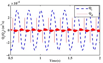
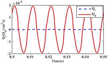
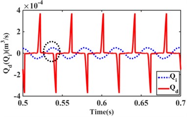
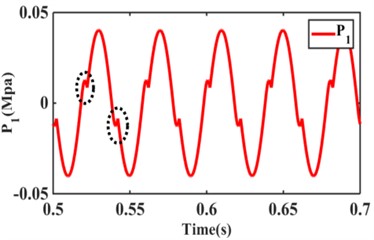
Fig. 4 shows the variation of flow and for the inertial channel and decoupler membrane channel at frequency 5 Hz, amplitude 3.0 mm and frequency 100 Hz, amplitude 0.05 mm. The flow through the decoupler membrane channel at frequency 5 Hz and amplitude 3.0 mm are negligible. At 100 Hz, the flow through the decoupler membrane channel is greater than that of the inertial channel. It can be seen that the inertia channel plays a role in hydraulic mounts at low frequency-large amplitude, while the decoupler membrane channel plays a major role in hydraulic mount vibration isolation at high frequency-small amplitude. The excitation frequency 25 Hz, amplitude 0.5 mm, the inertia channel, decoupler membrane channel flow as well as the pressure in the upper chamber have significant changes, as shown in Fig. 5. Among them, the inertial channel flow at the black oval of the paper in Fig. 5(a) is larger than the decoupler membrane channel flow, and the upper chamber pressure in Fig. 5(b) is slightly jumped at the black oval. The reason for this occurrence is the effect of the interaction of inertial channels and decoupler membrane channels.
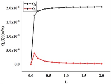
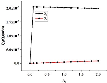
Fig. 6 shows the effect of variation in inertial channel length and cross-sectional area on the flow rate of the decoupler membrane channel. The decoupler membrane channel flow increases slightly with increasing inertial channel length. The flow rate of the decoupler membrane channel decreases slightly as the cross-sectional area of the inertial channel increases.
Fig. 4Inertial channel and decoupled membrane channel flow: a) f= 5 Hz, 3.0 mm; b) f= 100 Hz, 0.05 mm
a)
b)
Fig. 5Flow rate of inertial channel and decoupled membrane channel at 25 Hz, 0.5 mm: a) f= 5 Hz, 3.0 mm, b) f= 100 Hz, 0.05 mm
a)
b)
Fig. 6Effect of hydraulic mount inertia channel length and cross-sectional area variation on decoupling membrane channel flow: a) length variation, b) cross-sectional area variation
a)
b)
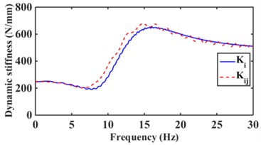
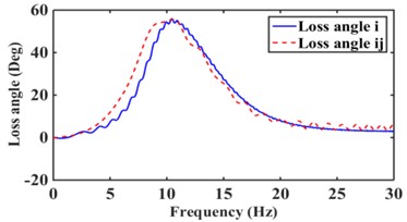
Fig. 7 shows the effect of the hydraulic mount with and without considering the decoupler membrane channel for frequency 0-30 Hz and amplitude 1.0 mm. As can be seen from Fig. 7, the decoupler membrane can change the dynamic characteristics of the hydraulic mounts.
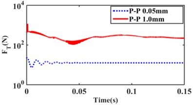
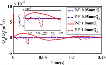
Fig. 8 shows the effect of the inertia channel and decoupler membrane channel on the hydraulic mount transfer force for the excitation amplitude 0.05 mm and 1.0 mm step response. Fig. 8(a) shows that the inertial channel flow can be neglected when the excitation amplitude 0.05 mm; from Fig. 8(b), it can be seen that the inertial channel and the decoupler membrane channel flow act simultaneously when the excitation amplitude 1.0 mm.
Fig. 7Effect of low frequency large amplitude decoupled membrane channel on dynamic characteristics of hydraulic mount: a) dynamic stiffness, b) loss angle
a)
b)
Fig. 8Effect of step response on hydraulic mount a) transfer force, b) inertia channel and decoupled membrane channel flow
a)
b)
2.3. Design of hydraulic mount for multi-inertia channel structure
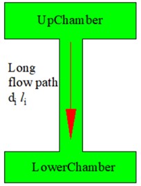
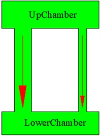
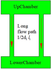
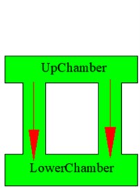
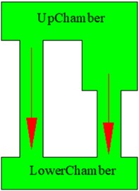
Because the characteristics of hydraulic mounts combining multiple inertia channels with decoupler membrane channel are less studied. Therefore, nine different combinations of inertia channels and decoupler membrane channel are proposed for hydraulic mounts. Fig. 9 shows the hydraulic mounts for different combinations of inertial and decoupled channels, Fig. 9(a) shows the mounts profile diagram and Fig. 9(b) shows the lumped parameter model of the hydraulic mounts. Where the flow rate of the th inertial channel is denoted by . Meanwhile, the hydraulic mount in Fig. 9 takes the same values and meanings as Fig. 1 for the rest of the parameters except for the dimensions of the inertia channel.
Fig. 9Multi-inertia channel hydraulic mount: a) profile diagram, b) lumped parameter model
a)
b)
Table 2 and Fig. 10(a) to 10(i) represent the structures of hydraulic mounts proposing nine different combinations of inertial and decoupler membrane channels, in respectively.
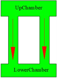
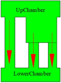
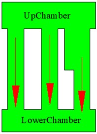
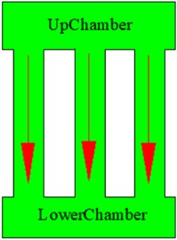
Fig. 10Multi-inertia channel hydraulic mount: a) single inertia channel with diameter di, and length Li, b) two inertia channels, with diameter di, and 1/2di length Li; c) two inertia channels, with diameter di and 1/2di length Li; d) two inertia channels, with diameter di and 1/2Li length; e) two inertia channels, both with diameter di, and 1/2Li length, respectively Li, and 1/2Li; f) 2 two inertial channels with the same structure and di length of Li; g) three inertial channels, all withdidiameter and length of Li, 1/2Li, 1/2Li; h) three inertial channels, all with di diameter and length of Li, Li, 1/2Li; i) three inertial channels with the same structure and di and the length is Li
a)
b)
c)
d)
e)
f)
g)
h)
i)
C1 structure is a single inertia channel hydraulic mount with cross-sectional area length, this structure and decoupled combination is currently used as a conventional hydraulic mount. C2-C6 focus on the number of inertia channels 2, changing the cross-sectional area of the inertia channels and the effect of the interaction between long inertia channels and decoupled membrane channels on the hydraulic mount characteristics. C2 inertia channel length is the same, change the cross-sectional area of the inertia channel, the diameter of the inertia channel, and 1/2, the length is the same as C1. C3 inertia channel length is the same, the diameter of the two inertia channels is 1/2, and the length is the same as C1. The C4 structure have two inertial channels of the same length and cross-sectional area, where the length is half of C1. C5 structure has two inertia channels with the same cross-sectional area, but 1 inertia channel is half the length of C1. The C6 structure have two inertial channels with the same cross-sectional area and both inertial channels have the same length as C1. The number of inertial channels 2 studied mainly by Zhang [8] proposed two inertial channels with different diameters and different inertial channel lengths and structures C2 and C5 similar. C7-C9 focus on the number of inertial channels 3, and similarly, changes the cross-sectional area and length of the inertial channels. three inertial channels of the C7 structure have the same cross-sectional area, but one of them has the same length as C1, and the other two are half of C1. C8 structure have three inertia channels with the same cross-sectional area, while two of them have the same length as C1 and the other one is half of C1. C9 structure has three inertia channels with the same cross-sectional area and the same inertia channel length as C1.
Table 2Hydraulic mounts with different configurations of inertia channels
Fig. 9 Numbering of inertial channels | Description |
C1 | One inertial channel with diameter , length |
C2 | Two inertial channels with diameter , 1/2 and length |
C3 | Two inertia channels with diameter 1/2, length |
C4 | Two inertia channels with diameter , length 1/2 |
C5 | Two inertial channels with diameter , length and 1/2 |
C6 | Two inertia channels with diameter length |
C7 | Three inertial channels with diameter , length , 1/2 and 1/2 |
C8 | Three inertial channels with diameter , length , and 1/2 |
C9 | Three inertial channels with diameter , length |
3. Multi-inertia channel and decoupled membrane channel interactions on hydraulic mount characteristics analysis
(1) To analyze the effect of changes in the number of inertial channels and decoupler membrane interactions on the hydraulic mount characteristics and to compare the changes in the mount characteristics of the three structures C1, C6, and C9. (2) To analyze the effect of the change in the cross-sectional area of the inertia channel and the interaction of the decoupler membrane on the hydraulic mount characteristics and to compare the change in the mount characteristics of the three structures C1, C2, and C3. (3) To analyze the effect of long inertia channel variation and decoupler membrane interaction on the hydraulic mount characteristics and to compare the variation of the mount characteristics of three structures C4, C5, and C6. (4) To analyze the effect of short inertia channel variation and decoupler membrane interaction on the hydraulic mount characteristics, the variation of the mount characteristics of three structures C7, C8 and C9 are compared.
The mathematical model of the multi-inertia channel hydraulic mount can be obtained with reference to the references [4, 5, 6, 16] and Fig. 9 as shown below:
where 1, 2, 3..., the first term , on the right side of Eqs. (8) (9) represents the pressure drop generated by the inertia coefficient of the fluid in the nth inertia channel and the decoupler membrane channel, and the second term , represents the pressure drop generated by the viscous damping of the fluid in the nth inertia channel and the decoupler membrane channel. The remaining symbols of Eqs. (8)-(14) have the same meaning as in Section 1.
3.1. Low-frequency dynamic characteristics of multi-inertial channels interacting with decoupled membrane channels
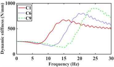
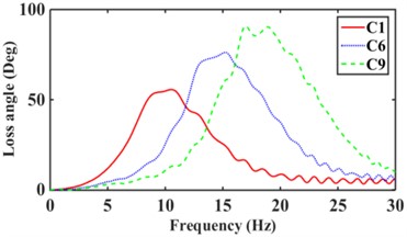
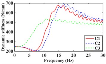
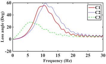
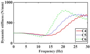
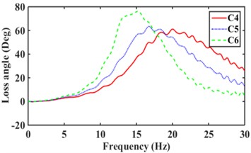
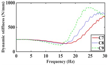
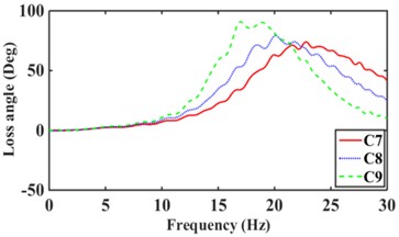
The road surface is the main excitation source for the low frequency of the mounts system. where the excitation amplitude 1.0 mm, frequency 0-30 Hz [17]. According to Eqs. (8-14), the dynamic stiffness and loss angle of hydraulic mounts with different combinations of inertia channels are obtained, as shown in Fig. 11. From Fig. 11(a), it can be seen that increasing the number of inertia channels broadens the dynamic stiffness and loss angle peak frequency of the hydraulic mounts. Among them, the peak frequency of dynamic stiffness and the peak frequency of loss angle of the hydraulic mounts from C1 to C9 structures increased from 14.8 Hz and 10.1 Hz to 24 Hz and 18.7 Hz, respectively, which are the same as the conclusion of the reference [8]. Fig. 11(b) shows that although the sum of the cross-sectional areas of the hydraulic mounts of the C3 structure is the same as that of C1; However, the hydraulic mounts of the C3 structure have a larger stiffness and loss angle at low frequency. It can be seen that the reduced cross-sectional area of the inertia channel hydraulic mounts exhibits greater stiffness and damping at a lower frequency. Fig. 11(c) shows that the peak frequencies of dynamic stiffness and loss angle for the hydraulic mounts of C4, C5, and C6 structures are 29.5 Hz and 20 Hz, 26.2 Hz and 16.7 Hz, and 19.8 Hz and 14.9 Hz, respectively. It can be seen that increasing the number of long inertia channels decreases the dynamic stiffness and loss angle peak frequency of the hydraulic mounts. Fig. 11(d) shows that increasing the number of short inertia channels increases the hydraulic mount dynamic stiffness and loss angle peak frequency from 24.3 Hz and 16.9 Hz to 29.8 Hz and 22.9 Hz, respectively, for the same number of inertia channels.
A comprehensive comparison of Fig. 11 shows that changing the number and length of inertia channels and the cross-sectional area at low frequency has the greatest effect on the low-frequency dynamic stiffness and loss angle of the hydraulic mounts.
Fig. 11Low-frequency dynamic stiffness and loss angle of hydraulic mounts: a)-b) C1, C6, C9, c)-d) C1, C2, C3, e)-f) C4, C5, C6, g)-h) C7, C8, C9
a)
b)
c)
d)
e)
f)
g)
h)
3.2. Relative displacement transmissibility of multi-inertia channel hydraulic mounts interacting with decoupler membrane channels
The relative displacement transmissibility between the engine and the vehicle frame at low frequency excitation as an important criterion of the mounts' vibration isolation performance [16, 20]. Where the relative engine to vehicle frame displacement transmissibility, , is given in Eq. (15):
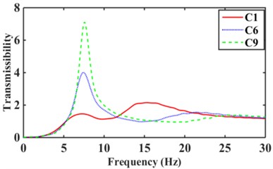
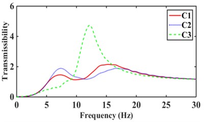
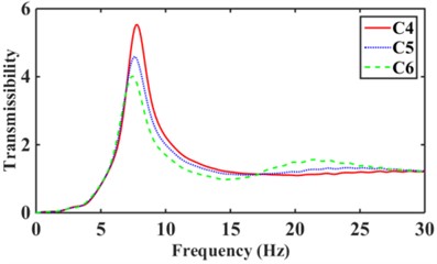
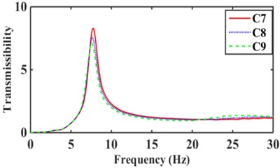
According to Eq. (15), nine inertial channels can be obtained in 0-30 Hz hydraulic mounts with relative displacement transmissibility Td, see Fig. 12. The maximum relative displacement transmissibility of the C1, C6, and C9 structures hydraulically mount in Fig. 12(a) are 2.52, 4.01, and 7.12, respectively. It can be seen that the relative displacement transmissibility of the hydraulic mounts decreases as the number of inertia channels increases. The relative displacement transmissibility of C2 hydraulic mounts with small cross-sectional area inertia channels added to C1 inertia channels is smaller than that of C1 and C3, as shown in Fig. 12(b). Fig. 12(c) shows that by increasing the number of long inertia channels, the relative displacement transmissibility of the mounts decreases. The hydraulic mounts of the C6 structure have a relative displacement transmissibility of 4.01 less than the 5.54 of C4 and 4.59 of C5. Fig. 12(d) shows that the relative displacement transmissibility of the hydraulic mounts increases from 7.12 for C9 to 7.56 for C8 and 8.31 for C7; It can be seen that increasing the number of short inertia channels affects the mounts' vibration isolation performance.
Fig. 12Relative displacement transmissibility of hydraulic mounts: a)-b) C1, C6, C9, c)-d) C1, C2, C3, e)-f) C4, C5, C6, g)-h) C7, C8, C9
a)
b)
c)
d)
3.3. High-frequency dynamic characteristics of multi-inertia channel hydraulic mounts interacting with decoupled membrane channels
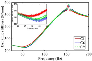
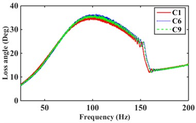
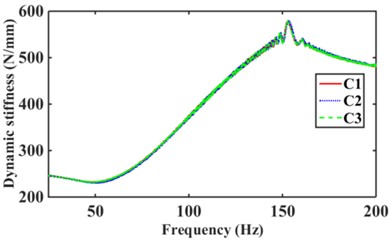
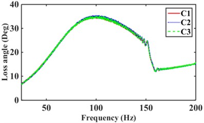
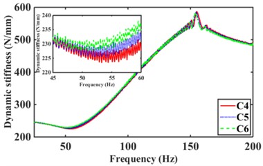
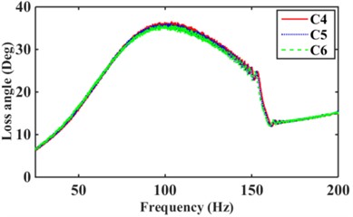
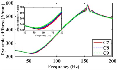
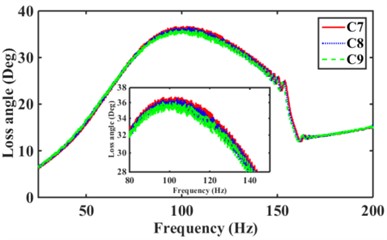
The engine is the main excitation source for the mounts high frequency with amplitude 0.05 mm and frequency 25 Hz-200 Hz [2, 18, 19]. Fig. 13 shows the effect of the different numbers of inertia channels, cross-sectional area, and the number of long and short inertia channels on the high-frequency dynamic characteristics of the hydraulic mounts. As can be seen in Fig. 13(a), the peak frequencies of the mounts' high-frequency dynamic stiffness and loss angle increase as the number of inertial channels increases. It can be seen that the high frequency-small amplitude affects the dynamic characteristics of hydraulic mounts in addition to the decoupler channel effect also related to the number of inertia channels. Fig. 13(b) shows that the dynamic stiffness and loss angle curves of the hydraulic mounts of the three structures C1, C2, and C3 almost overlap. Therefore, the high-frequency small-amplitude excitation reduces the cross-sectional area of the inertia channel and has no effect on the dynamic characteristics of the hydraulic mounts. Fig. 13(c) shows that increasing the number of long inertia channels affects the high-frequency dynamic characteristics of the hydraulic mounts. Fig. 13(d) shows that with the same number of inertia channels, increasing the number of short inertia channels, the peak of the hydraulic mount's high-frequency dynamic stiffness and loss angle increases subsequently.
Combining Fig. 13(a)(b)(c) and (d), it is found that changing the number of inertia channels has the greatest effect on the high-frequency dynamic stiffness and loss angle of the hydraulic mounts, followed by the number of length inertia channels while reducing the cross-sectional area of the inertia channels has the least effect.
Fig. 13Hydraulic mount at high frequency dynamic stiffness and loss angle for: a)-b) C1, C6, C9, c)-d) C1, C2, C3, e)-f) C4, C5, C6, g)-h) C7, C8, C9
a)
b)
c)
d)
e)
f)
g)
h)
4. Time-frequency domain characterization of multi-inertia channel hydraulic mounts interacting with decoupled membrane channels
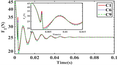
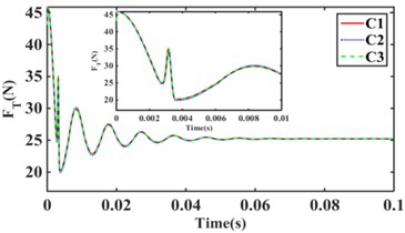
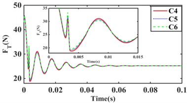
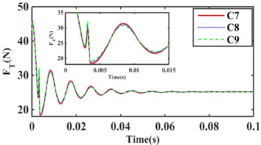
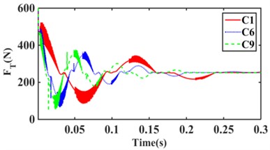
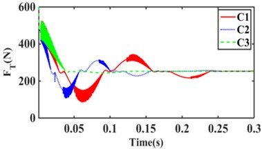
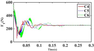
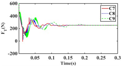
Fig. 14 and Fig. 15 show the variation of hydraulic mount transfer force at amplitude 0.1 mm and 1.0 mm for 9 inertia channels for 4 combination schemes, respectively.
4.1. 0.1 mm amplitude step response
From Fig. 14(a), it can be seen that the hydraulic mounts’ transfer force decreases as the number of inertia channels increases; Therefore, increasing the number of inertia channels is beneficial to the hydraulic mounts' vibration isolation. Fig. 14(b) shows that the RMS of the transmitted forces of the hydraulic mounts of C1, C2, and C3 structures are all 25.74 N; It can be seen that the smaller inertia channel cross-sectional area cannot change the vibration isolation performance of the small amplitude hydraulic mounts. Fig. 14(c) finds that increasing the number of long inertia channels as well as 14(d) increasing the number of short inertia channels benefits the hydraulic mounts for vibration isolation. Therefore, the decoupler membrane channel of the hydraulic mounts under small amplitude excitation plays a major contribution. However, the number of inertia channels and the number of long and short inertia channels also directly affect the vibration isolation performance of the hydraulic mounts.
Fig. 14Hydraulic mount at 0.1 mm step response transfer force: a) C1, C6, C9, b) C1, C2, C3, c) C4, C5, C6, d) C7, C8, C9
a)
b)
c)
d)
4.2. 1.0 mm amplitude step response
Fig. 15(a) shows that the RMS values of C1, C6, and C9 transfer forces are 260.80 N, 258.90 N, and 258.18 N, respectively, for the excitation amplitude 1.0 mm step response; As can be seen, C9 has the smallest RMS of transfer force. Meanwhile, C9 has the largest overshoot and oscillation period. Fig. 15(b) shows that the RMS values of transfer forces for C1, C2, and C3 structural hydraulic mounts are 260.80 N, 259.53 N, and 270.10 N, respectively, with C2 having the smallest RMS value. It can be seen that the smaller cross-sectional area of the inertia channel can improve the vibration isolation performance of the hydraulic mounts. Fig. 15(c) shows that the C4 structure has the smallest RMS value of 256.71 N for the hydraulic mount’s transfer force. Fig. 15(d) shows that the C7 structure has the smallest RMS value of 256.36 for the hydraulic mount's transfer force. It can be seen that the increase of the short inertia channel is beneficial to improve the vibration isolation performance of hydraulic mounts. In summary, it can be seen that hydraulic mounts can cause oscillations in the system when subjected to large excitation amplitudes and when the decoupler membrane channel fluid commutates to flow. Meanwhile, under large amplitude excitation, although the inertial channel plays a dominant role in the hydraulic suspension; However, a small amount of fluid flows through the decoupler membrane channel.
Fig. 15Hydraulic mount at 1.0 mm step response transmitted force: a) C1, C6, C9, b) C1, C2, C3, c) C4, C5, C6, d) C7, C8, C9
a)
b)
c)
d)
5. Conclusions
The article is an analysis of the effect of different inertial channels interacting with decoupler membrane channels on the performance of hydraulic mounts. (a) Firstly, the hydraulic mounts for nine different inertia channels are proposed. The mounts are designed to include: different numbers of inertia channels, different cross-sectional areas of inertia channels, and different numbers of long and short inertia channels. Secondly, the mathematical model of multi-inertia channel hydraulic mounts is solved. Also, the effects of the number of inertia channels, cross-sectional area, and the interaction between the number of long and short inertia channels and the decoupler membrane on the dynamic characteristics and vibration isolation performance of the mounts are analyzed. Finally, the effects of different combinations of inertial channels and decoupled membrane channels interacting with the mounts in time domain characteristics are analyzed for excitation amplitudes 0.1 mm and 1.0 mm.
The results show that changing the number and length of inertia channels as well as the cross-sectional area at low frequency has the greatest effect on the dynamic characteristics of the hydraulic mounts; Increasing the number of long inertia channels, can improve the low-frequency vibration isolation performance of decoupler membrane hydraulic mounts. Changing the number of inertia channels has the greatest effect on the high-frequency dynamic stiffness and loss angle of the hydraulic mounts. Under large amplitude excitation, not only the inertia channel should be considered for hydraulic mounts, but also the decoupler membrane channel has a small amount of fluid flowing through it. Therefore, the role of the decoupler membrane channel is also considered.
References
-
Shangguan Wen-Bin, “Engine mounts and powertrain mounting systems: a review,” International Journal of Vehicle Design, Vol. 49, No. 4, pp. 237–258, 2009, https://doi.org/10.1504/ijvd10.1504/ijvd. 2009.024956
-
R. Singh, G. Kim, and P. V. Ravindra, “Linear analysis of automotive hydro-mechanical mount with emphasis on decoupler characteristics,” Journal of Sound and Vibration, Vol. 158, No. 2, pp. 219–243, Oct. 1992, https://doi.org/10.1016/0022-460x(92)90047-2
-
G. Kim and R. Singh, “Nonlinear analysis of automotive hydraulic engine mount,” Journal of Dynamic Systems, Measurement, and Control, Vol. 115, No. 3, pp. 482–487, Sep. 1993, https://doi.org/10.1115/1.2899126
-
A. Geisberger, A. Khajepour, and F. Golnaraghi, “Non-linear modelling of hydraulic mounts: theory and experiment,” Journal of Sound and Vibration, Vol. 249, No. 2, pp. 371–397, Jan. 2002, https://doi.org/10.1006/jsvi.2001.3860
-
J.-Y. Yoon and R. Singh, “Indirect measurement of dynamic force transmitted by a nonlinear hydraulic mount under sinusoidal excitation with focus on super-harmonics,” Journal of Sound and Vibration, Vol. 329, No. 25, pp. 5249–5272, Dec. 2010, https://doi.org/10.1016/j.jsv.2010.06.026
-
J.-Y. Yoon and R. Singh, “Dynamic force transmitted by hydraulic mount: Estimation in frequency domain using motion and/or pressure measurements and quasi-linear models,” Noise Control Engineering Journal, Vol. 58, No. 4, p. 403, 2010, https://doi.org/10.3397/1.3449082
-
Shangguan Wen, Song Zhi-Shun, and Zhang Yun-Qing, “Experimental study and simulation analysis of hydraulic engine mounts with multiple inertia tracks,” (in Chinese), Journal of Vibration Engineering, Vol. 18, No. 3, pp. 318–323, 2005.
-
Y.-Q. Zhang and W.-B. Shangguan, “A novel approach for lower frequency performance design of hydraulic engine mounts,” Computers and Structures, Vol. 84, No. 8-9, pp. 572–584, Mar. 2006, https://doi.org/10.1016/j.compstruc.2005.11.001
-
B. Barszcz, J. T. Dreyer, and R. Singh, “Experimental study of hydraulic engine mounts using multiple inertia tracks and orifices: Narrow and broad band tuning concepts,” Journal of Sound and Vibration, Vol. 331, No. 24, pp. 5209–5223, Nov. 2012, https://doi.org/10.1016/j.jsv.2012.07.001
-
C.-F. Yang, Z.-H. Yin, W.-B. Shangguan, and X.-C. Duan, “A study on the dynamic performance for hydraulically damped rubber bushings with multiple inertia tracks and orifices: parameter identification and modeling,” Shock and Vibration, Vol. 2016, pp. 1–16, 2016, https://doi.org/10.1155/2016/3695950
-
Yang C. et al., “Experiment and calculation of the low frequency performance of a hydraulic bushing with multiple tracks,” Journal of Vibration, Measurement and Diagnosis, Vol. 36, No. 6, pp. 1057–1064, 2016, https://doi.org/10.16450/j.cnki.issn.1004-6801.2016.06.004
-
T. Chai, J. T. Dreyer, and R. Singh, “Frequency domain properties of hydraulic bushing with long and short passages: System identification using theory and experiment,” Mechanical Systems and Signal Processing, Vol. 56-57, pp. 92–108, May 2015, https://doi.org/10.1016/j.ymssp.2014.11.003
-
T. Chai, J. T. Dreyer, and R. Singh, “Time domain responses of hydraulic bushing with two flow passages,” Journal of Sound and Vibration, Vol. 333, No. 3, pp. 693–710, Feb. 2014, https://doi.org/10.1016/j.jsv.2013.09.037
-
T. Chai, R. Singh, and J. Dreyer, “Dynamic stiffness of hydraulic bushing with multiple internal configurations,” SAE International Journal of Passenger Cars – Mechanical Systems, Vol. 6, No. 2, pp. 1209–1216, May 2013, https://doi.org/10.4271/2013-01-1924
-
M. Lu, J. Ari-Gur, and J. Garety, “Prediction of automotive hydrobushing resonant frequency,” ASME 1999 International Mechanical Engineering Congress and Exposition, Vol. 26, pp. 157–159, Nov. 1999, https://doi.org/10.1115/imece1999-0193
-
Y. Li, J. Z. Jiang, and S. A. Neild, “Optimal fluid passageway design methodology for hydraulic engine mounts considering both low and high frequency performances,” Journal of Vibration and Control, Vol. 25, No. 21-22, pp. 2749–2757, Nov. 2019, https://doi.org/10.1177/1077546319870036
-
J. E. Colgate, C.-T. Chang, Y.-C. Chiou, W. K. Liu, and L. M. Keer, “Modelling of a hydraulic engine mount focusing on response to sinusoidal and composite excitations,” Journal of Sound and Vibration, Vol. 184, No. 3, pp. 503–528, Jul. 1995, https://doi.org/10.1006/jsvi.1995.0330
-
K. H. Lee, Y. T. Choi, and S. P. Hong, “Performance design of hydraulic mount for low frequency engine vibration and noise control,” International Off-Highway and Powerplant Congress and Exposition, Vol. 1, pp. 1–12, Sep. 1994, https://doi.org/10.4271/941777
-
M. Brach and A. G. Haddow, “On the dynamic response of hydraulic engine mounts,” Noise and Vibration Conference and Exposition, Vol. 1, pp. 463–474, May 1993, https://doi.org/10.4271/931321
-
M. S. Foumani, A. Khajepour, and M. Durali, “A new high-performance adaptive engine mount,” Journal of Vibration and Control, Vol. 10, No. 1, pp. 39–54, Jan. 2004, https://doi.org/10.1177/1077546304031474
About this article

Science and Technology Guidance Project in Sanming City (2020-G-57). Fujian Province, China. China National Innovation and Entrepreneurship Training Program for college students (201911311010). Authors were supported by a grant from the Science and Technology Plan Project (2018Z016) of Quanzhou City, Fujian Province, China for the research in this paper. Sanming University introduced high-level talents scientific research start-up funding (Project number: 23YG01). Sanming City Guiding Science and Technology Plan Project (Project number: 2023-G-1).
The datasets generated during and/or analyzed during the current study are available from the corresponding author on reasonable request.
The authors declare that they have no conflict of interest.
