Abstract
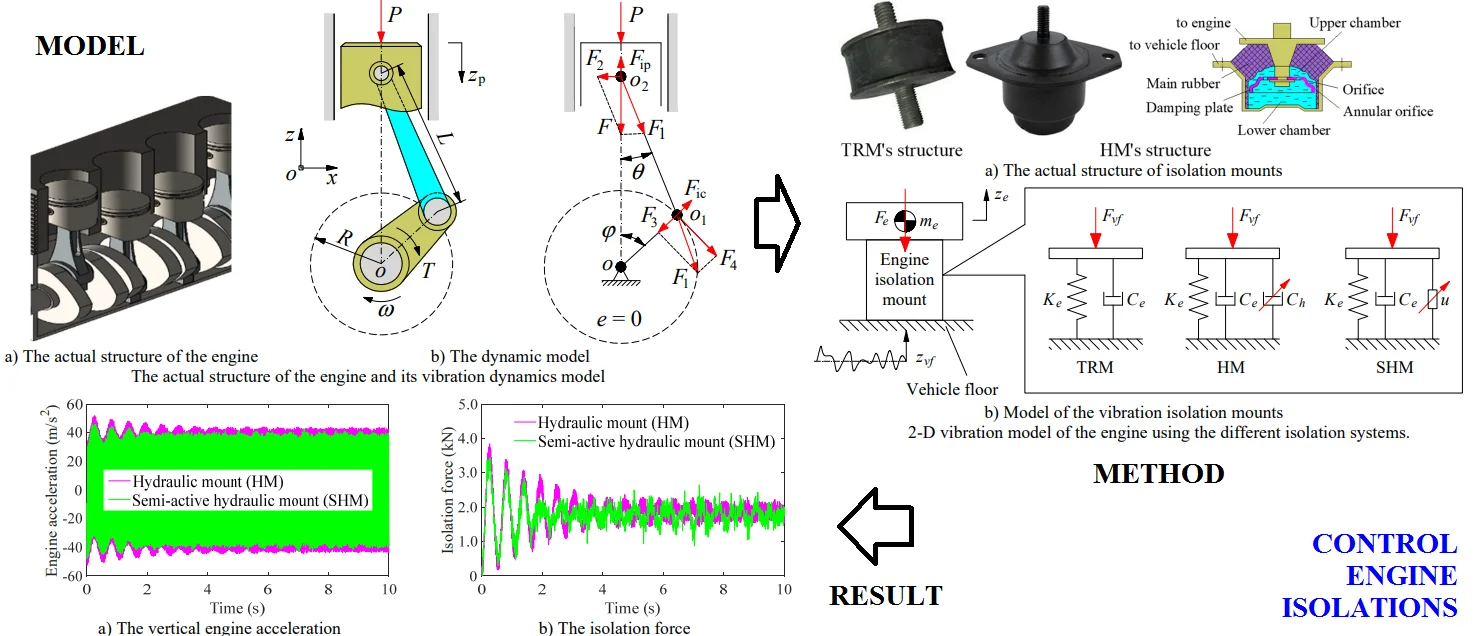
To evaluate the effect of the engine vibration on the vehicle's ride comfort and improve the vehicle's ride comfort, three types of engine’s isolation systems including the traditional rubber mount (TRM), hydraulic mount (HM), and semi-active HM controlled by the PID control (SHM) are proposed. A dynamic model of the inline 4-cylinder engine is established to determine the excitation force of the engine. By the combination of the random excitation of the vehicle floor affecting the engine isolation system, the isolating performance of the TRM, HM, and HM is then simulated and evaluated on isolating the engine vibration and improving the vehicle’s ride comfort. Both the root mean square (RMS) values of the engine acceleration response () and isolation force () of engine isolation systems are given as the objective functions. The research results show that the engine vibration combined with the excitation of the road surface roughness significantly affects the vehicle’s ride comfort. By using the SHM, both the engine acceleration and isolation force are significantly reduced in comparison with the TRM. Especially, the values of the and are remarkably decreased by 9.32 % and 9.69 % in comparison with the TRM. Thus, to improve the vehicle's ride comfort and reduce the effect of the engine's vibration on the ride comfort, the engine isolation system used by the TRM needs to be replaced by using the SHM.
Highlights
- Three types of engine’s isolation systems including the traditional rubber mount (TRM), hydraulic mount (HM), and semi-active HM controlled by the PID control (SHM) are proposed.
- A dynamic model of the inline 4-cylinder engine is established to determine the excitation force of the engine.
- By using the SHM, both the engine acceleration and isolation force are significantly reduced in comparison with the TRM. Especially, the values of the 𝑎_RMSe and 𝐹_RMS are remarkably decreased by 9.32 % and 9.69 % in comparison with the TRM.
- To improve the vehicle's ride comfort and reduce the effect of the engine's vibration on the ride comfort, the engine isolation system used by the TRM needs to be replaced by using the SHM.
1. Introduction
Improving the ride comfort of vehicles has always been of particular interest to researchers. To study this issue in detail, the influence of the vehicle’s design parameters as well as the suspension system had been analyzed and evaluated [1-3]. Optimizing the design parameters of the suspension systems had been made to improve the ride comfort [1, 4]. Studies showed that the vehicle’s ride comfort had been significantly improved. However, under the vibration excitations of random road surfaces when the vehicle moved at a high speed, the vehicle's ride comfort was also significantly limited. To solve this problem, air suspension systems are gradually being studied and replaced by steel spring suspension systems [5-8]. Further developed are the vehicle’s semi-active and active control suspension systems. The results indicated that the vehicle’s ride comfort had been further enhanced.
However, in most of the above studies, it was shown that the vibration excitation source of vehicles was the main cause of the vibration and determines the ride comfort of vehicles, and most of the above studies only considered the main source of excitation caused by the rough road surface during the interaction of the wheels with the road surface. Meanwhile, the vibration source of the engine transmitted to the vehicle floor also significantly affects the ride comfort of vehicles. However, this issue was mostly ignored in the vibration study of vehicles. This had not yet fully reflected the influence of vibration sources on the ride comfort of vehicles. Therefore, during the design of vehicles, the vehicle's performance may not be fully optimized.
The vibration studies on internal combustion engines showed that, in the low frequency regions of the engine below 100 Hz, the acceleration response of the engine was relatively high [9-11], and it also significantly affected the ride comfort of vehicles when the engine's vibration excitation was combined with the vibration excitation from the rough road surface. Besides, the existed studies had also shown that the engine isolation system mainly used by the traditional rubber mount (TRM) had not yet been effective enough in isolating vibrations of the engine. Based on the effectiveness of the hydraulic mount (HM) had been researched and applied on the vehicle's cab isolation systems [7, 12-14], the HM was being interested and applied to the vibration isolations of the engine. However, the effect of the HM was mainly considered by the excitation force of the harmonic function of a single-engine cylinder. In fact, the excitation force of the engine was generated by the synthesis of the cylinders during the operation of the engine. In addition, the vibration excitation from the rough road surface has a great influence on the vehicle’s ride comfort and has not been considered in the study of the vibration isolations of the engine.
To solve these problems, a dynamic model of the inline 4-cylinder engine is considered to determine the excitation force of the engine on the engine isolation system. By the combination of the random excitation of the vehicle floor affecting the engine isolation system, three types of the engine isolation systems including the TRM, HM, and HM controlled by the PID control [15-16] are then proposed and studied for the efficiency of them on isolating the engine vibration and improving the vehicle’s ride comfort. Both the root mean square (RMS) values of the engine acceleration response () and isolation force () of engine isolation systems are given to evaluate the efficiency of three types of isolation systems. Reducing both the and are the goal of this study.
2. Mathematical methods
2.1. The vibration dynamics model of the ICE
To calculate the vibration source in the operating process of the engine, a dynamic model of the slider-crank-mechanism (SCM) is established, as shown in Fi. 1. Herein, is the pressure of the gas acting on the top of the piston during combustion; is the crankshaft radius; is the connecting rod length; is the crankshaft’s angular velocity; is the inertial force of the piston-small rod end; is the centrifugal inertial force of the big rod end of the connecting rod; is the total force of the and ; is the acting forces of the piston on the connecting rod, cylinder, and crankpin bearing ( 1, 2, 3, 4), respectively.
Fig. 1The actual structure of the engine and its vibration dynamics model
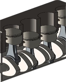
a) The actual structure of the engine
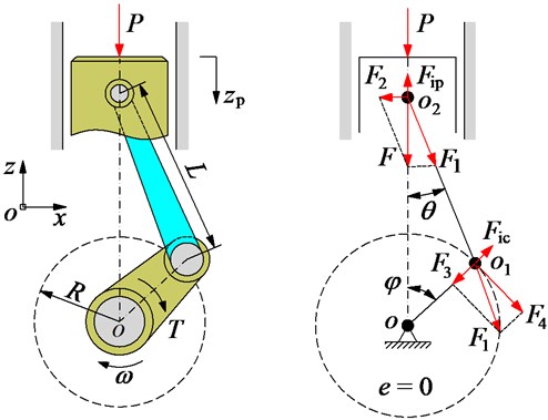
b) The dynamic model
Based on the dynamic model of the SCM in Fig. 1(b), the piston’s stroke in the -direction is determined as follows:
where the relationship between the connecting rod length and the crankshaft radius is calculated as follows:
Applying Newton equation for Eq. (2), we can obtain:
By replacing Eq. (3) into Eq. (1) and the mathematical transformation, the vertical acceleration response of the piston has been expressed as follows:
Based on the kinematics of the SCM’s structure in Fig. 1(b), the impacting forces of , , and are calculated by:
The vibration dynamic equation of the engine in the vertical direction of one piston is determined by:
The engine in Fig. 1(a) uses four cylinders in line, and the working order of the pistons is 180°, accordingly, the total of the vibration dynamic force in the vertical direction of the engine acting on the engine isolation mount is expressed by:
Therefore, the dynamic force is used as a vibration source of the engine acting on the engine isolation system to control the engine’s vibration.
2.2. The ICE isolation model
2.2.1. Mathematic model of the traditional rubber mount
To reduce vibrations from the engine transmitted to the floor of the vehicle during work, the traditional rubber mount was almost used on the engine isolation mounts [7, 12, 13]. The TRM's structure and model include a stiffness coefficient and damping coefficient , as plotted in Fig. 2.
Under the acting force of the on the engine isolation mount, the vertical force response of the TRM is expressed as follows:
Due to the low performance of the TRM in isolating the engine vibrations, thus, a type of hydraulic mount (HM) with its high isolating performance used on the off-road vehicle cab [7] is proposed and applied on the engine isolation mounts in Section 2.2.2.
2.2.2. Mathematic model of the hydraulic mount
The HM's structure includes the main rubber and the damping plate driven by the bolt and a closed chamber filled with the fluid, as shown in the same Fig. 2(b). The HM’s dynamic model is also plotted in the same Fig. 2(b). Herein, the and also are the stiffness and damping coefficients of the main rubber; is the damping coefficient of the fluid in the damping plate of the HM. Based on the research result in Refs. [13-16], the vertical force response of the HM is written as follows:
where is the vibration excitation from the vehicle floor and is the engine vibration in its operating process.
Fig. 22-D vibration model of the engine using the different isolation systems.
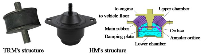
a) The actual structure of isolation mounts
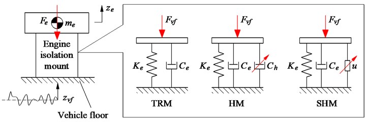
b) Model of the vibration isolation mounts
2.2.3. Mathematic model of the semi-active hydraulic mount
To further reduce vibrations from the engine transmitted to the floor of the vehicle during work, the damping coefficient of the is then proposed and controlled by an active control force . The model of semi-active HM is also shown in the same Fig. 2(b). Therefore, the vibration equation of the engine with the different isolation systems can be derived as follows:
Herein, the active force is determined by:
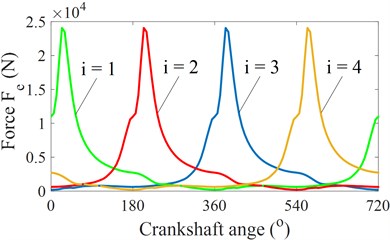
Fig. 3The vibration dynamics force of the ICE acting on the engine isolation mounts
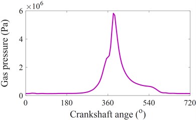
a) Pressure of gas
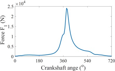
b) Force acting on the crankshaft
c) Force acting on the crankshaft
d) Total force of engine
e) Total force acting on the isolation mount
2.3. Vibration excitation of the mathematical model
2.3.1. The vibration excitation of the engine
To determine the vibration excitation source of the engine, the gas pressure in a cylinder measured based on the experiment result at 2000 rpm of an engine in Ref. [10-11], as shown in Fig. 3(a), is used to calculate the impacting forces of and .
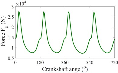
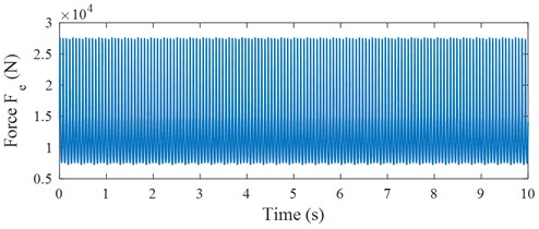
Based on the dynamic parameters of the engine listed in Table 1 and the dynamic equations of SCM in Eqs. (1) to (7), the force acting on the crankshaft, force acting on the crankshaft, and total force of the engine in one engine cycle ( 720°) are then calculated and plotted in Fig. 3(b), 3(c), and 3(d), respectively. Based on the vertical excitation force of the engine with the crankpin angle 720o in Fig. 3(d), the vertical excitation force of changed in the time region is plotted in Fig. 3(e). The excitation force Fe of the engine in the time region is then used as the acting force on the engine isolation mount to evaluate the isolating performance of the engine in Eq. (10).
2.3.2. The vibration excitation of the vehicle floor
The road surface roughness is always used to evaluate the vehicle vibration. To establish the rough road, a periodic modulated random process of the random excitation in Ref. [6-7] is calculated by the experimental formula:
where is the space-frequency; 0.1 m-1 is the reference space-frequency; is the power spectral density of the road surface under the reference space-frequency; is the road surface roughness coefficient; and 2 is the frequency index.
Assuming that the rough road is the zero-mean stationary Gaussian random, the equation of the road surface roughness is expressed via the inverse Fourier transformation as follows:
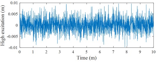
where is the random phase uniformly distributed from 0 to 2. Based on a typical road surface roughness in ISO 8068 [17], the vibration excitation of the vehicle floor acting on the engine mounts is then simulated and plotted in Fig. 4. The vibration excitations in Fig. 3(e) and 4 are then applied to simulate and evaluate the performance of engine isolation mounts.
Fig. 4The vibration excitation of the vehicle floor acting on the engine mounts
2.4. Evaluating index
To evaluate the performance of the engine isolation mounts in improving the engine and vehicle vibrations, two evaluating indexes of the reducing the root-mean-square acceleration () of the engine and the reducing the root-mean-square force response of isolation mount () are chosen as the objection functions. Both the values of and are expressed as follows [18]:
where and are the acceleration and force responses in the simulation time .
3. The PID controller and application
To control the vehicle suspension system, some control methods are applied, such as fuzzy logic control, PID control, control, combined control methods [7, 15, 16]. However, the PID control not only has a high performance but also is a simple structure. The equation of the PID control is described as follows [15]:
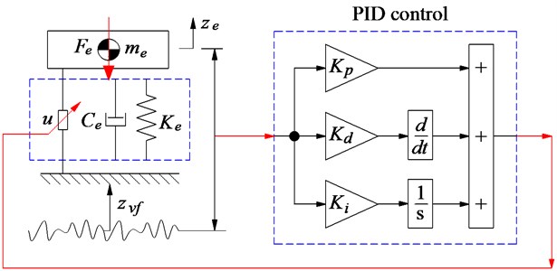
where the constant coefficients of , , and are defined as the proportionality factors of the PID control, is the vertical displacement of the engine isolation mount and is the input value of the PID control, and is the active force of the engine isolation mount calculated by the PID control. The model of the PID control applied on the engine isolation mount is plotted in Fig. 5.
Fig. 5Simulink model of the control system
To determine the optimal values of the , , and , based on the Ziegler-Nichols technique, the control model in Fig. 5, and the simulation parameters of engine isolation mount in Table 1, the optimal parameters of , , and are then obtained by 2446, 1233, and 45, respectively. These optimal parameters are then applied to control the active isolation system of the engine.
Table 1Dynamic parameters of the engine and isolation mount.
Parameters | Values | Parameters | Values |
(m) | 129.5×10⁻³ | (kg) | 0.250 |
(m) | 40×10-3 | (kg) | 250 |
(kg) | 0.264 | (N/m) | 25000 |
(kg) | 0.345 | (Ns/m) | 250 |
(kg) | 0.095 | (Ns/m) | 9804 |
4. Simulation and analysis results
To evaluate the effect of the different vibration sources as well as the performance of the TRM, HM, or SHM on isolating the engine vibrations, the dynamic parameters of the engine and isolation mount in Table 1, the excitation sources in Fig. 3(e) and 4 are then applied to simulate and evaluate the results.
4.1. Effect of the vibration excitation from the vehicle floor
With the engine using the TRM, under the excitation of the vehicle floor in Fig. 4, the simulation results show that both the engine acceleration and isolation force are significantly increased compared to without the excitation of the vehicle floor, as seen in Fig. 6(a) and 6(b). Also, based on the calculation results of both the and listed in Table 2, the result of the is increased by 1.36 % while the result of the is increased by 1.22 % in comparison without the excitation of the vehicle floor. This means that under the effect of the vehicle floor excitation combined with the engine vibration in the working process, the vehicle's ride comfort is significantly reduced in comparison without the vehicle floor excitation. Thus, the engine’s TRM needs to be improved by using the better isolation system of the HM.
Fig. 6The acceleration and force responses of the engine and isolation mount
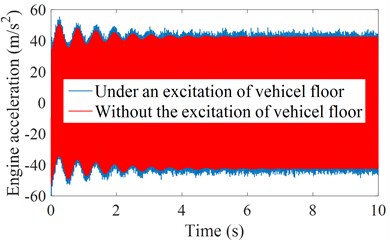
a) The vertical engine acceleration
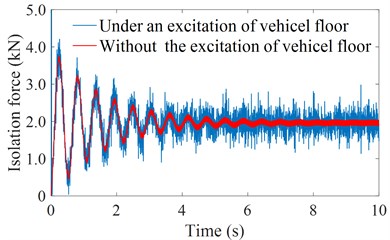
b) The isolation force
Table 2The RMS results of the engine isolation mount using the TRM.
RMS values | Without the excitation of the vehicle floor | Under excitation of the vehicle floor | Increase |
(m/s2) | 36.3185 | 36.3679 | 1.36 % |
(kN) | 2.0039 | 2.0264 | 1.22 % |
4.2. Performance of the HM
With the engine using the HM, under both the excitations of the vehicle floor and engine in Figs. 3(e) and 4, the simulation results of both the engine acceleration and isolation force with the TRM and HM are plotted in Figs. 7(a) and 7(b). Observing the results in Fig. 7, we can see that both the engine acceleration and isolation force with the HM are significantly reduced in comparison with using the TRM. Especially, Table 3 indicates that the calculation results of both the and using the HM are significantly reduced by 5.20 % and 4.89 %. This also means that with using the HM, the effect of the engine vibration on the vehicle’s ride comfort is reduced in comparison with using the TRM. Thus, the use of the HM on the engine isolation mounts is the current trend. However, the research results also show that the performance of the HM is not really high, thus, to further enhance the HM’s performance, the control of the HM is then presented in Section 4.3.
Fig. 7The acceleration and force responses of the engine under different isolation mounts
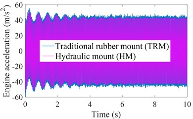
a) The vertical engine acceleration
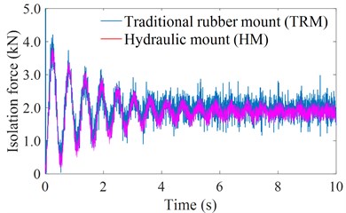
b) The isolation force
Table 3The RMS results of the engine isolation mount using the TRM and HM
RMS values | With TRM | With HM | Reduction (%) |
(m/s2) | 36.3679 | 34.5290 | 5.10 % |
(kN) | 2.0264 | 1.9273 | 4.89 % |
4.3. Performance of the SHM
With the active force of the SHM controlled by the PID control in Fig. 5 under both the excitations of the vehicle floor and engine, the simulation results of both the engine acceleration and isolation force are also simulated and shown in Figs. 8(a) and 8(b). Besides, the calculation results of the and using the SHM are also listed in Table 4.
The results in Fig. 8 show that both the engine acceleration and isolation force with the HM controlled by the PID control is lower than that of the engine’s HM without control, concurrently, the values of the and using the SHM is improved by 4.48 % and 5.05 % in comparison with the HM without control; and by 9.32 % and 9.69 % in comparison with the engine’s isolation mount using the TRM. Therefore, both the engine's vertical vibration and the impacting force of the engine isolation system on the vehicle floor are reduced. This means that the vehicle’s ride comfort is significantly improved by using the HM controlled by the PID control.
Fig. 8The acceleration and force responses of the engine with the HM and SHM
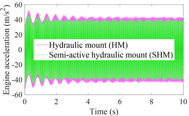
a) The vertical engine acceleration
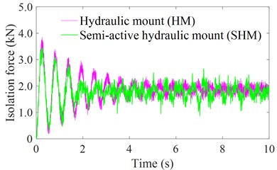
b) The isolation force
Table 4The RMS results of the engine isolation mount using the SHM
RMS values | With HM | With SHM | SHM versus HM (%) | SHM versus TRM (%) |
(m/s2) | 34.5290 | 32.9801 | 4.48 % | 9.32 % |
(kN) | 1.9273 | 1.8299 | 5.05 % | 9.69 % |
5. Conclusions
With the combination of both the vibration excitations of the engine and vehicle floor, the engine acceleration and isolation force of the TRM on the vehicle floor is increased compared to using only excitation of the engine. Thus, the engine vibration combined with the excitation of the road surface roughness significantly affects the vehicle's ride comfort.
With using the HM and SHM, both the RMS values of the engine acceleration and isolation force are significantly reduced in comparison with the engine isolation system using the TRM. Especially with the SHM, both the values of the and are decreased by 9.32 % and 9.69 % in comparison with the TRM.
Therefore, to improve the vehicle’s ride comfort and reduce the effect of the engine’s vibration on the ride comfort, the engine isolation system used by the TRM needs to be changed by using the HM or semi-active HM.
References
-
V. Nguyen, Y. Ye, and Y. Hu, “Vibration research of heavy trucks. Part 2: Optimization of vehicle dynamic parameters,” Journal of Mechanical Engineering, Automation and Control Systems, Vol. 1, No. 2, pp. 124–133, Dec. 2020, https://doi.org/10.21595/jmeacs.2020.21814
-
V. Nguyen, Y. Hu, and Y. Ye, “Vibration research of heavy trucks. Part 1: Sensitivity analysis of dynamic parameters on ride comfort,” Journal of Mechanical Engineering, Automation and Control Systems, Vol. 1, No. 2, pp. 114–123, Dec. 2020, https://doi.org/10.21595/jmeacs.2020.21813
-
V. Nguyen, R. Jiao, and J. Zhang, “Control performance of damping and air spring of heavy truck air suspension system with optimal fuzzy control,” SAE International Journal of Vehicle Dynamics, Stability, and NVH, Vol. 4, No. 2, pp. 179–194, Feb. 2020, https://doi.org/10.4271/10-04-02-0013
-
Z. He, W. Gong, W. Xie, J. Zhang, G. Zhang, and Z. Hong, “NVH and reliability analyses of the engine with different interaction models between the crankshaft and bearing,” Applied Acoustics, Vol. 101, pp. 185–200, Jan. 2016, https://doi.org/10.1016/j.apacoust.2015.07.014
-
G. Tang, H. Zhu, Y. Zhang, and Y. Sun, “Studies of air spring mathematical model and its performance in cab suspension system of commercial vehicle,” SAE 2015 World Congress and Exhibition, Vol. 2015, No. 4, pp. 341–348, Apr. 2015, https://doi.org/10.4271/2015-01-0608
-
Nguyen V. et al., “Performance analysis of semi-active hydraulic system of the off-road vibratory roller cab using optimal fuzzy-PID control,” Journal of Southeast University, Vol. 35, pp. 399–407, 2019.
-
V. Nguyen, J. Zhang, and X. Yang, “Low-frequency performance analysis of semi-active cab’s hydraulic mounts of an off-road vibratory roller,” Shock and Vibration, Vol. 2019, pp. 1–15, Apr. 2019, https://doi.org/10.1155/2019/8725382
-
V. Nguyen et al., “Performance analysis of air suspension system of heavy truck with semi-active fuzzy control,” Journal of Southeast University, Vol. 33, pp. 159–165, 2017.
-
X. Meng, L. Ning, Y. Xie, and V. W. Wong, “Effects of the connecting-rod-related design parameters on the piston dynamics and the skirt-liner lubrication,” Proceedings of the Institution of Mechanical Engineers, Part D: Journal of Automobile Engineering, Vol. 227, No. 6, pp. 885–898, Jun. 2013, https://doi.org/10.1177/0954407012464025
-
V. Nguyen and D. Yan, “The influence of the SCM structure parameters on the engine vibration and optimization the engine power,” Journal of Mechanical Engineering, Automation and Control Systems, Vol. 2, No. 6, pp. 9–18, Jan. 2021, https://doi.org/10.21595/jmeacs.2021.21868
-
W. Hua, “A sensitivity analysis of SCM dynamic parameters on improving the engine vibration and power,” Vibroengineering PROCEDIA, Vol. 36, pp. 1–6, Mar. 2021, https://doi.org/10.21595/vp.2020.21809
-
S. Jiao, Y. Wang, L. Zhang, and H. Hua, “Shock wave characteristics of a hydraulic damper for shock test machine,” Mechanical Systems and Signal Processing, Vol. 24, No. 5, pp. 1570–1578, Jul. 2010, https://doi.org/10.1016/j.ymssp.2009.12.005
-
P. Lee, J. Vogt, and S. Han, “Application of hydraulic body mounts to reduce the freeway hop shake of pickup trucks,” SAE 2009 Noise and Vibration Conference and Exhibition, May 2009, https://doi.org/10.4271/2009-01-2126
-
F. Yi and M. Xie, “Objective evaluation of engine mounting isolation,” AASRI Procedia, Vol. 3, pp. 49–53, 2012, https://doi.org/10.1016/j.aasri.2012.11.009
-
V. Nguyen and M. Tian, “Control performance of suspension system of cars with PID control based on 3D dynamic model,” Journal of Mechanical Engineering, Automation and Control Systems, Vol. 1, No. 1, pp. 1–10, Jun. 2020, https://doi.org/10.21595/jmeacs.2020.21363
-
B. Kasemi, A. G. A. Muthalif, M. M. Rashid, and S. Fathima, “Fuzzy-PID controller for semi-active vibration control using magnetorheological fluid damper,” Procedia Engineering, Vol. 41, pp. 1221–1227, 2012, https://doi.org/10.1016/j.proeng.2012.07.304
-
“ISO 8068, Mechanical Vibration-Road Surface Profiles – Reporting of Measured Data,” Geneve, Switzerland, International Organization for Standardization, 1995.
-
“ISO 2631-1, Mechanical vibration and shock-Evanluation of human exposure to wholebody vibration, Part I: General requirements,” The International Organization for Standardization, 1997.
About this article

This research was supported by Open Fund Project of Hubei Key Laboratory of Intelligent Transportation Technology and Device, Hubei Polytechnic University, China (No. 2021XZ107).
