Abstract
Telescopic handler is combined of truck crane and forklift. Equipped with different accessories, the telescopic handler can achieve fork loading, lifting and other operations. Large amount of energy is needed to maintain lifting and lowering in large range with high frequency of the working device of telescopic handler. There is no energy recycling device for the working device that leads to the large dissipating of gravitational potential energy. In order to recycle the wasted energy, a three-chamber hydraulic cylinder boom system (TCCBS) is proposed. In this paper, the recycling principle is described. Then the energy consumption characteristics are analyzed. Further, the mode of TCCBS of telescopic handler is established and analyzed. Compared with the double chamber cylinder boom system (DCCBS), the single-action time of the boom is reduced 4.15 s. The velocity shock decrease from 0.12 m/s to 0.02 m/s at the beginning of the boom lowering process. The peak pressure decreased from 24 MPa to 21 MPa and the average pressure decreased from 17 MPa to 13 MPa during boom lifting process. The potential energy recycling of the working device is 139 kJ, which accounts for about 47.1 % of total potential energy. The cumulative output energy of TCCBS is 311 kJ, which is 92 kJ less than the DCCBS. The comprehensive energy saving efficiency is 22.3 %. The results show that the TCCBS can realize the potential energy recycling.
Highlights
- To solve the problem that the waste of potential energy of the working device on telescopic handler, a three-chamber hydraulic cylinder boom system (TCCBS) is proposed to recycle the wasted energy.
- The mathematical model of energy efficiency characteristics using energy flow analysis method is novel, and the results provide a basis for system optimization.
- A complete simulation model of the mechanical-electrical-hydraulic boom system is established in the AMESIM environment. The simulation results show that the potential energy recycling efficiency of the working device is 47.1% and the comprehensive energy saving rate of the TCCBS is 22.3%.
1. Introduction
This paper is about the research on the potential energy recycling of telescopic handler by using TCCBS. The telescopic handler is combined of the truck crane and forklift. It can reach a farther distance and a higher working height by changing the length and amplitude of telescopic boom. The gravitational potential energy of the working device is increased with the length and amplitude of telescopic boom. Large amount of energy is needed to maintain lifting and lowering of the working device on telescopic handler with high frequency. A large amount of the gravitational potential energy is dissipated by the throttling effect of the control valve. That leads to raises the temperature of hydraulic oil rapidly. The cooling system should be added to reduce the temperature which further aggravates the energy loss [1]. Therefore, it is an effective energy saving measure to recycle the gravitational potential energy of working device for the telescopic handler.
In the existing research, several main methods of gravitational potential energy recycling are as follows: electrical method, hydraulic-electric coupling method, hydraulic method and hydraulic-gas energy storage balancing method et al. Regarding electrical recycling method, an energy recycling unit [2] based on a generator coupled with a hydraulic motor was used to convert the boom gravitational potential energy into electrical energy. The electrical energy is stored in batteries, supercapacitors or a combination of the both [3]. Generally, this type of system is needed to add additional energy utilization units [4]. The energy recycling device based on hydraulic motor-pump-electrical motor in the energy recycling system of excavator boom was proposed [5], [6]. This method can reduce energy delivery path to some extent. Lin et al used the electrohydraulic coupling method to recycle the gravitational potential energy [7]. The recovered energy was firstly stored in the hydraulic accumulator. When the pressure of the accumulator reached the threshold, it would be recovered by the generator. Both electrical recycling and hydraulic-electric coupling methods are suitable for oil-electric hybrid power [8], [9] or pure electric driving engineering machinery [10], [11]. Also, the electric driving system and high-power energy storage unit have the disadvantages of high control cost [12] and poor system reliability [13], [14], which restrict the application and popularization. In addition, the recovered energy needs to be converted through multiple mechanical-hydraulic-electric conversions, and energy utilization rate efficiency is low [15].
For the hydraulic recycling method, the hydraulic accumulator directly recycles the gravitational potential energy. The flow of rod-less cylinder is pressed into the hydraulic accumulator when the boom lowers. However, the difficulty is to achieve the pressure matching between the hydraulic cylinder and the hydraulic accumulator. Therefore, a throttle valve is arranged to control the hydraulic cylinder descent speed [16]. The recovered energy can be converted to mechanical energy reuse through torque coupling method or directly reused through flow coupling method. Kim et al proposed that the high-pressure oil of the accumulator drives the hydraulic motor to assist the power source [17]. Amrhein et al proposed that the stored hydraulic energy can be driven the cooling system or other auxiliary devices [18]. The shortage is that the utilization of energy is greatly limited. And only the device with low working pressure can be driven [19]. It can also be applied to drive the hydraulic pump. The high-pressure oil of the accumulator was introduced into the inlet of the hydraulic pump to achieve reutilization [20]-[21]. However, the suction port of the hydraulic pump is required to withstand high pressure. In addition, the hydraulic accumulator high-pressure oil is introduced into the multiway valve inlet to realize reuse. But the disadvantage is that there is secondary throttling loss in the recycling process, which reduces the utilization efficiency [22]. A new hydraulic transformer [23] and the asymmetrical pump controlled differential cylinder system [24] were used to solve the problem of secondary throttling loss.
For hydraulic-gas energy storage balancing method, Liang proposed the principle of independent hydraulic cylinder balancing the weight of the working device in his doctoral thesis [25]. Its motion characteristics and energy efficiency were analyzed and tested. Gong et al proposed the potential energy recycling method based on a principle of alternate recycling of multiple hydraulic cylinders, and analyzed and tested its working performance and energy efficiency on SWE330LC [26]. The system has high energy efficiency, but the original system structure is changed greatly. This is not suitable for the single hydraulic cylinder driving boom system. A hydraulic-gas energy storage balancing method was proposed to recycle the gravitational potential energy of the working device [27]-[29]. This research method has been theoretically and experimentally applied to 6 t and 76 t excavators. The system structure is simple, and the energy saving efficiency is high. It is especially suitable for working devices with single or more hydraulic cylinder driving. For hydraulic recycling methods and hydraulic-gas energy storage balancing method, the accumulator is essential for potential energy recycling system. Therefore, the parameters of the accumulator have a great influence on the operating characteristics and energy consumption characteristics. The effect of pre-charge pressure and volume of accumulators on energy efficiency of the system was analyzed, but there is no basis for selecting appropriate parameters [30].
In summary, there are many energy conversion steps in the electric recycling system, and the recycling efficiency is lower. Appling the novel hydraulic transformer to the hydraulic recycling systems has high energy recycling efficiency. However, with the complex structure and high cost, the research of the novel hydraulic transformer device are still in the initial stage and not yet been commercialized. The potential energy recycling system based on alternate recycling theory of multiple hydraulic cylinders has high energy saving efficiency. However, the original system structure is changed greatly due to the addition of hydraulic-gas energy storage balancing cylinder. Also, it is not suitable for the system with single hydraulic cylinder driving. In order to overcome the above deficiencies, a three-chamber cylinder boom system (TCCBS) is proposed in this paper. The three-chamber hydraulic cylinder can be regarded as a combination of piston cylinder and plunger cylinder. The piston rod and plunger rod divide the hydraulic cylinder into three-chamber. One chamber is connected with the accumulator. Set the accumulator pressure to basically balanced with the working device. This method can be applied to the system of single hydraulic cylinder driving boom without change greatly the structure. The introduction to the study is made in Chapter 1. The remainder of this paper is organized as follows. The material and method are explained in Chapter 2. The energy characteristic analysis is analyzed in Chapter 3. The key components and complete system simulation models of DCCBS and TCCBS are studied in Chapter 4. The results of simulation are discussed and compared with previous studies in Chapter 5. The conclusions are presented in Chapter 6.
2. Material and method
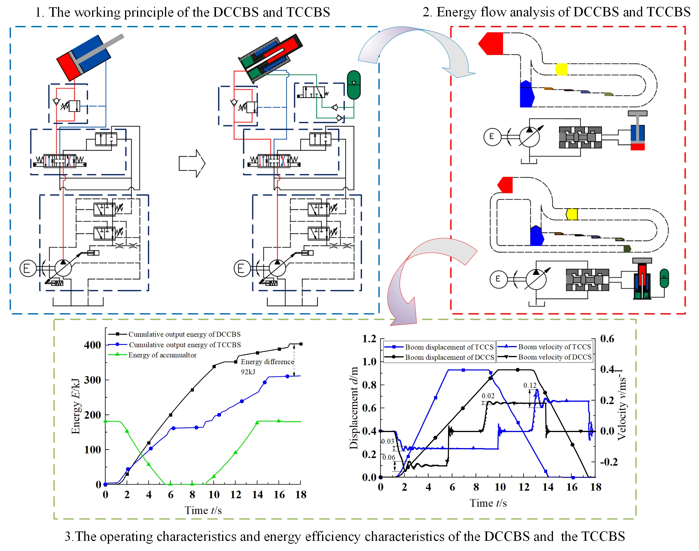
On the basis of analyzing the gravitational potential energy recycling system of hydraulic hybrid lifting machinery, a TCCBS of telescopic handler is proposed. Its system structure and working principle is compared to the DCCBS, as shown in Fig. 1. The potential energy recycling system replaces general hydraulic cylinder driving the boom with a three-chamber hydraulic cylinder. It is also equipped with an accumulator. The counterweight chamber C is connected with the accumulator to balance the gravity of the working device. And a controllable pressure keeping valve is set to switch the oil connection between the counterweight chamber and the accumulator.
The DCCBS adopts the load independent flow distribution system. Under the action of the control signal, the multiway directional valve works at the left position, the pressure oil provided by the variable pump passes through the multiway directional valve and balance valve to provide power for the double chamber hydraulic cylinder, lifting the load. When the multiway directional valve works in the right position, the pressure oil enters the rod chamber to make the load lower.
Fig. 1The working principle of the DCCBS and TCCBS
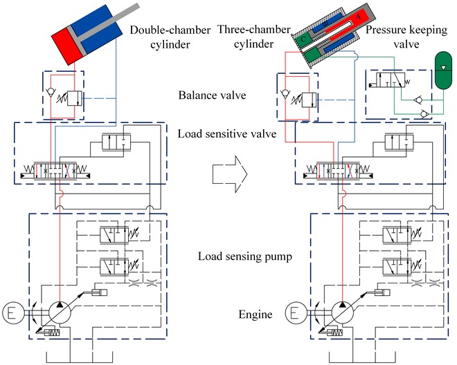
For the TCCBS, under the action of the control signal, the multiway directional valve and the controllable pressure keeping valve work at the left position. The pressure oil output by the variable pump enters the chamber A, and the high-pressure oil of the accumulator enters the chamber C. The boom is lifted to the specified position, achieving the utilization of the potential energy of the working device. Under the action of the control signal, the multiple directional control valve and the controllable pressure keeping valve work at the right position. The flow output by the variable pump enters chamber B. The high-pressure oil of chamber A flows back to the tank, and the high-pressure oil of chamber C is pressed into the accumulator. The boom lowers to the specified position, achieving the recovery of the potential energy of the working device. During the boom lowering, the variable pump only provides low pressure oil preventing cavitation because the boom is under negative load. In addition, when the resistance of the hydraulic accumulator is too large, the variable pump offers the TCCBS enough flow rate to make the boom lower.
3. Energy efficiency characteristic analysis
In order to obtain the energy consumption of the TCCBS, the energy analysis of each component of the boom system is performed. The energy efficiency analysis between the DCCBS and the TCCBS is compared as follows.
Total energy consumption of DCCBS during boom lifting is described by:
where, is the inlet energy of the hydraulic cylinder, is the outlet energy of the hydraulic cylinder, is the energy required for the boom to lift, is the energy loss of the pump and valve:
where, and are the pressure and flow at the inlet of hydraulic cylinder, and are the pressure and flow at the outlet of hydraulic cylinder:
where, is the loss energy of hydraulic pump and is the loss energy of hydraulic valve.
The energy loss of the hydraulic pump is due to volumetric loss and mechanical loss. The total energy loss of the pump is given as:
where, is pump mechanical loss, for pump volumetric loss:
where, is the torque loss of the pump, is the speed of the pump:
where, is the flow loss of the pump, the outlet pressure of the pump.
The energy loss of hydraulic valve mainly caused by three parts: the overflow loss of relief valve, unloading valve and throttling loss of working valve, which are calculated as follows:
where, is energy loss caused by relief valve, is energy loss caused by unloading valve, is throttling loss caused by working valve:
where, is the flow of the relief valve, is the flow of the relief valve.
During the boom lowering, the rod chamber of double chamber hydraulic cylinder maintains a certain pressure to prevent air suction. The energy consumption of the DCCBS is calculated as follows:
where, and are the inlet pressure and flow of double chamber hydraulic cylinder with rod chamber, respectively. is the energy loss of pump and valve.
Therefore, in the DCCBS, the total energy consumption in the boom up and down a cycle is expressed as:
Since there is no energy recycling device, the waste of energy in the DCCBS is expressed as:
In the TCCBS, the counterweight chamber C and chamber A jointly drive the boom to lift, the energy consumption of the system is described as:
where, is the energy at the outlet of three chamber hydraulic cylinder, is the loss energy of hydraulic pump and hydraulic valve, is the energy released by accumulator:
where, and are inlet pressure and flow of chamber B respectively.
The energy loss of hydraulic pump and hydraulic valve of the TCCBS is the same as the DCCBS, that is :
where, is the minimum working pressure of the accumulator, is the corresponding volume, is the inlet flow of the chamber C.
During the boom lowering process, the energy consumption of the TCCBS is expressed as:
where, the and are the inlet pressure and flow of the chamber B, respectively. is the energy loss of the pump and the valve.
The counterweight chamber C is filled with hydraulic oil to the accumulator, and the gravitational potential energy of the working device is converted into hydraulic energy. The stored energy is calculated as:
where, is the maximum working pressure of the accumulator, is the corresponding volume, is the outlet flow of the chamber C.
During the lowering process, the accumulator is filled with hydraulic oil under the pressure of the chamber B and the gravity of the working device. The gravitational potential energy of the working device recovered by the accumulator is expressed as:
Therefore, the total energy consumption of the TCCBS is calculated as:
In summary, the potential energy recycling rate of TCCBS is expressed as:
During one cycle of boom working, the energy saving effect of the TCCBS is expressed as:
4. Modeling and simulation
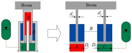
To evaluate the feasibility and energy saving of the TCCBS. The simulation model of the DCCBS and the TCCBS are assembled in AMESIM environment. The structure parameters required by the system are from the Caterpillar TH514C telescopic handler. According to the principle shown in Fig. 1 and the parameters, the key components of the telescopic handler are modeled.
4.1. Working device model
The working device is composed of a boom, a telescopic boom, a forklift. Its dynamics model is based on the CAD model parameters (hinge point size, inertia, mass et cl.). The simulated force acting on the boom cylinder can be calculated by this model. The force of telescopic handler boom is shown in Fig. 3. Assuming that point O is the origin of coordinate, the horizontal direction is axis, and the vertical direction is axis. The operating trajectory of telescopic handler working device is the rotation movement around point O, and its equivalent rotational inertia is expressed as:
where, , and are the mass of boom, telescopic boom, and cargo fork respectively. , and are the moment of inertia of boom, telescopic boom and cargo fork relative to their own center of gravity respectively. , and are the distance from the center of gravity of boom, telescopic boom and cargo fork to the hinge point O respectively.
Fig. 2Energy flow analysis of DCCBS and TCCBS
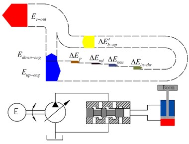
a) Energy flow analysis of DCCBS
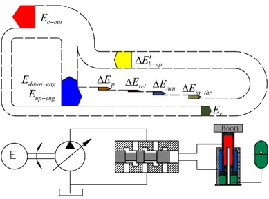
b) Energy flow analysis of TCCBS
Fig. 3Boom force diagram of telescopic handler
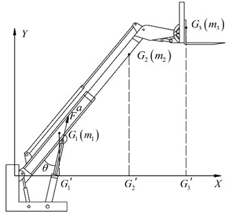
The resultant force of boom at hinge point I is F, and the torque balance equation at hinge point O is calculated as:
where, is the distance between the hinge point O and the hinge point I; is the acceleration of the boom along the direction of the hydraulic cylinder at the hinge point I; is the equivalent moment of inertia of boom, telescopic boom and fork around the point O.
From Newton’s second law:
According to Eqs. (25-27), the equivalent mass of the telescopic handler working device at the hinge point I is described as:
The 3-DoF working device model is established according to the parameters obtained from the above formula.
4.2. Model of load sensitive pump
The boom system of Caterpillar TH514C telescopic handler adopts load independent flow distribution system. This system not only has the characteristics of energy saving, but also has good control performance. The use of a load independent flow distribution system requires a load sensitive pump, making the oil pressure of the pump is always higher than the load pressure by a small pressure difference (about 2 MPa). When the multiway directional valve changes the opening of the valve port, the pump can automatically adjust and output the flow corresponding to the load speed, regardless of the load size. This can achieve the matching between the output flow of the pump and the demand of the load. In the AMESIM component library call variable pump and load sensitive valve and pressure compensation valve. A load sensitive pump is composed of these components, and then enter the appropriate parameters.
4.3. Load sensitive multiway directional valve model
Since the AMESIM component library does not have a multiway directional valve for the boom system of the Caterpillar TH514C telescopic handler, a sensitive valve model is built based on the samples used. According to the working principle of multiway valve with pressure compensation, the appropriate components are selected from AMESIM model library and connected according to the working principle. Select mathematical models for components at different application levels. The global hydraulic parameters are defined, such as the bulk modulus, density, dynamic viscosity and working temperature of the working oil, and the key dimensions and internal parameters of each hydraulic component are defined. Set the simulation parameters and run the simulation, getting the similar results with the sample. Then parameters are applied in the boom system.
According to the working principle of telescopic handler shown in Fig. 1 and the above model, the working device model of telescopic handler with DCCBS is assembled, as shown in Fig. 4.
4.4. Three chamber hydraulic cylinder model
Due to there are no special components like three chamber hydraulic cylinder in the AMESIM component library, the model is established by using two double chamber hydraulic cylinders according to the area parameters of each chamber, as shown in Fig. 5:
According to Eqs. (29-32), , , , can be calculated.
Fig. 4Simulation model of DCCBS
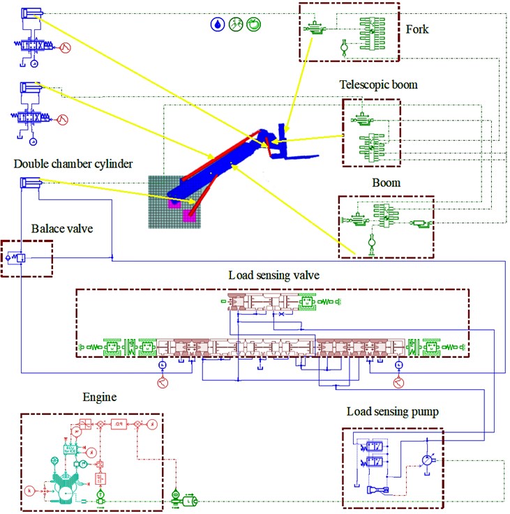
Fig. 5Three chamber hydraulic cylinder model
4.5. Hydraulic accumulator model
The accumulator modeling needs to meet the following principles. Firstly, the effective volume of the hydraulic accumulator is greater than or equal to the volume under the three-chamber hydraulic cylinder chamber C effective stroke. In other words, the hydraulic accumulator can recover all the recoverable oil during the lowing of the boom. Secondly, the working pressure of the hydraulic accumulator cannot be too high, otherwise the power of the pump will be increased and the dynamic performance will be reduced during the boom lowing. Thirdly, during boom lifting, the working pressure of the hydraulic accumulator is so low that chamber C balance working device is not obvious, so it needs to ensure that the minimum working pressure close to the pressure caused by the working device. At last, the installation space of telescopic handler is compact, the space of reserved hydraulic accumulator is limited, and the volume of hydraulic accumulator is as small as possible.
The volume calculation of hydraulic accumulator is calculated as:
where, is the pre-charge pressure of the hydraulic accumulator, is the corresponding gas volume; is the minimum working pressure, is the gas volume under the lowest working pressure; is the maximum working pressure, is the gas volume under the highest working pressure. is the effective volume.
Fig. 6Simulation model of TCCBS
The effective stroke of hydraulic cylinder piston rod is , the effective working volume of accumulator is described as:
According to the lifting process and static state of the DCCBS, the minimum working pressure of the hydraulic accumulator is determined to be 12 MPa by the pressure curve of the rod-less chamber of the hydraulic cylinder. In order to ensure the life of the hydraulic accumulator, the smaller the ratio of is, the longer the life of the hydraulic accumulator is, and is set. Therefore, the is determined to be 12 MPa and the is 24 MPa. The pre-charge pressure is . The parameters of hydraulic accumulator are shown in Table 1.
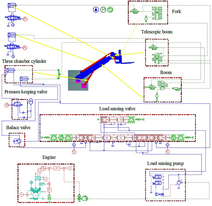
Based on the above main component model and the working principle shown in Fig. 1, the TCCBS mode of the telescopic handler is shown in Fig. 6. The main parameters of simulation model are illustrated in Table 2.
Table 1Five sets parameters of hydraulic accumulator
(MPa) | (MPa) | (MPa) | (L) | (L) |
7 | 12 | 24 | 23.6 | 90 |
8 | 12 | 24 | 23.6 | 80 |
9 | 12 | 24 | 23.6 | 75 |
10 | 12 | 24 | 23.6 | 70 |
11 | 12 | 24 | 23.6 | 65 |
Table 2Main parameters of simulation model
Component | Parameters | Quantity |
Working device | Total weight Rated load | 13000 kg 4500 kg |
Engine | Rated power Rated speed | 82 kw 2000 rpm/min |
Hydraulic pump | Rated displacement Rated pressure | 135 ml/min 32 MPa |
Double chamber cylinder | Area of rod-less chamber Area of rod chamber | 37994 mm2 20331.5 mm2 |
Three-chamber cylinder | Area of chamber A Area of chamber B Area of chamber C | 20096 mm2 9498.5 mm2 25434 mm2 |
5. Discussion
In order to analyze the operating characteristics and energy efficiency of the TCCBS. The simulation of the lifting and lowering action of the boom is completed in the established model.
The comparative curves of the characteristics of the boom motions are illustrated in Fig. 7. As can be seen that the average boom lifting speed in DCCBS is 0.12 m/s, while in TCCBS, the average boom lifting speed is 0.22 m/s. In addition, at the initial stage of the lifting process, the boom speed of shock increases from 0.2 m/s to 0.34 m/s. This is because that the addition of hydraulic accumulator breaks the matching relationship between pump and load. During the descent of boom, the load sensitive pump is in flow control despite the resistance of the hydraulic accumulator. The average speed of the two systems is almost the same. There are obvious velocity shocks due to the inertia of the working device in the process of accelerating to decline. The velocity shock decreases from 0.12 m/s to 0.02 m/s at the beginning of the boom lowering process. Therefore, the hydraulic accumulator also plays a good buffer effect in the lowering process.
The pressure curve of the boom cylinder and the pump of the DCCBS is illustrated in Fig. 8. From 0-0.76 s, the multiway directional valve is in the middle position, the pump is in the lower pressure standby condition. The pressure of the pump is the same as the set pressure of the load sensitive valve (about 2 MPa). In the lifting process form 0.76 s-10.05 s, the multiway directional valve is switched to the left position, and the boom is lifted. Due to the load sensitive valve through its own adjustment function, the pressure difference between the pump and the rod-less chamber of the hydraulic cylinder is always maintained at about 2 MPa. The peak pressure of the pump is 24 MPa, and the average pressure is 17 MPa. When the boom rises to the highest position, the hydraulic cylinder piston moves to the end of the stroke. From 10.05-11 s, the multiway directional valve does not switch, the pump and the hydraulic cylinder rod-less chamber pressure reaches maximum pressure of 32 MPa. During this period, the pump is in high pressure standby condition. When the multiway directional valve is switched to the median, the pump is unloaded from 11 s to 12 s, and the pump is in the minimum displacement state through the variable mechanism. The pump output pressure is the same as the set pressure of the load sensitive valve. The pump is in the lower pressure standby condition again. From 12 s to 17 s, the multiway directional valve is switched to the right position, and the boom lowers. At the moment of lowering, the pump output pressure reaches the peak pressure of 28 MPa. The pressure of the rod chamber and the gravity of the working device form a resultant force and act on the rod-less chamber of the boom cylinder. Due to the large gravity of the working device, the boom mainly depends on the gravity to lower. Therefore, the pressure of the rod chamber is very small. The pump is in the working state with the largest displacement. The average pressure of rod-less chamber is 7 MPa. The high-pressure oil of rod-less chamber flows back to the tank through the multiway directional valve. This throttling loss energy cannot be recycled.
Fig. 7Motion characteristics comparison
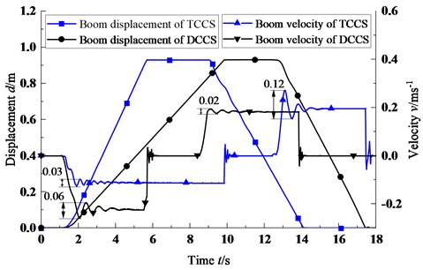
Fig. 8pressure curves of DCCBS
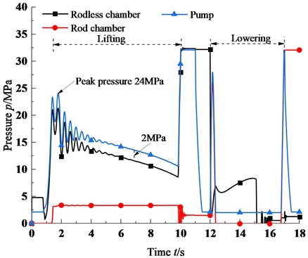
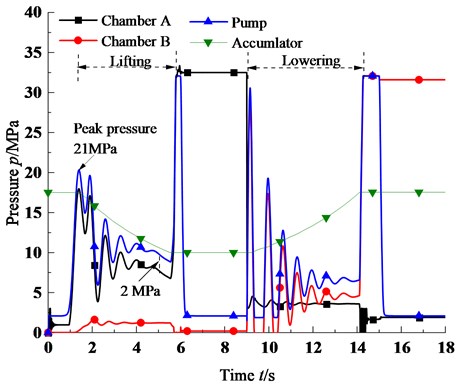
Fig. 9 shows the pressure curves of the three-chamber hydraulic cylinder, pump and hydraulic accumulator of TCCBS. During this period of lifting process from 0.76 s to 5.9 s, the oil of the hydraulic pump flows into the chamber A, and the high-pressure oil of the hydraulic accumulator enters the chamber C. The chamber B is connected to the tank. With the help of hydraulic accumulator, the pressure of the pump is obviously decreased. The peak pressure of the pump is 21 MPa, which is 3.5 MPa lower than that of the DCCBS. The average pressure is 13 MPa, which is 4 MPa lower than that of the DCCBS. The accumulator pressure decreases from 17.5 MPa to 10 MPa as the boom lifts. During the boom lowering from 9-14.31 s, the oil of the hydraulic pump flows into the chamber B, the chamber A receives the oil tank, and the high-pressure oil of chamber C is pressed into the accumulator. As the boom decreases, the accumulator pressure increases from 10 MPa to 17.5 MPa. Due to the accumulator exerts a resistance effect, the average pressure of the pump is 7 MPa higher than that of the DDCBS. The energy of the chamber A is dissipated through the multiway directional valve, which cannot be recycled.
Fig. 9Pressure curves of TCCBS
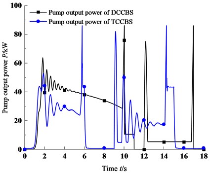
The power output comparison curves of hydraulic pumps for TCCBS and DCCBS are illustrated in Fig. 10. In the process of boom lifting, the average output power is 46 kW of DCCBS. In the TCCBS, the average output power is 32 kW. In the process of boom lowering process, due to overcoming the accumulator resistance, the average output power is 20 kW of the TCCBS, which is 5 kW higher than that of the DCCBS.
Fig. 10Comparison of system power curves
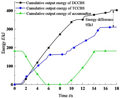
The accumulated output energy from pump and hydraulic accumulator is illustrated in Fig. 11. In the process of boom lifting, the energy consumption of DCCBS is 352 kJ, while the energy consumption of TCCBS is 163 kJ. The energy released by accumulator is 181 kJ. In the process of boom lowering, due to the effect of accumulator, the energy consumption of DCCBS is 148 kJ, which is higher than the DCCBS by 51 kJ. The energy recovered by accumulator is 181 kJ, which one of potential energy of the boom is 139 kJ according to Fig. 2. and Eqs. (1-21). During this period of boom working process, the energy consumption of DCCBS is 403 kJ, while the energy consumption of TCCBS is 311 kJ. Thus, according to Eqs. (22-24), the potential energy recycling efficiency of the TCCBS is 47.1 %; the comprehensive energy saving efficiency of the TCCBS is 22.3 %.
Fig. 11Comparison of cumulative output energy curves
Compared with other three potential energy recycling methods. For electrical recycling method, the potential energy recycling efficiency is 36 % because there are many energic conversion steps in the electric recycling system. Regarding the hydraulic recycling method, the potential energy recycling efficiency is 39 % due to the secondary throttling loss during utilization process. For potential energy recycling method based on a principle of alternate recycling of multiple hydraulic cylinders, the potential energy recycling efficiency is 45.2 %. Though it has high energy saving efficiency, the original system structure is changed greatly due to the addition of hydraulic-gas energy storage balancing cylinder. From the above discussion, The TCCBS not only high recycling efficiency and simple structure.
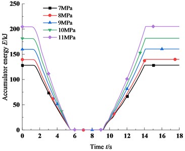
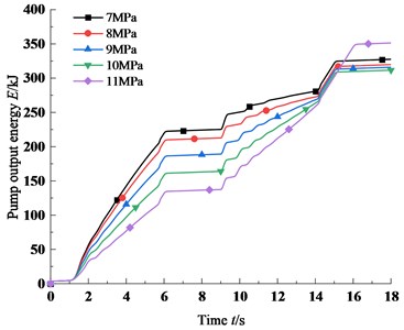
The influence of pre-charge pressure and volume of hydraulic accumulator on the charging and discharging characteristics is further analyzed by several sets of parameters in Table 1. The pre-charge pressure is set as 7 MPa, 8 MPa, 9 MPa, 10 MPa and 11 MPa respectively. The energy recovered by the accumulator and the cumulative output energy of TCCBS under different pre-charge pressure is in illustrated Table 3. The energy recycling characteristics is illustrated in Fig. 12(a). The system cumulative output energy characteristics under different pre-charge pressures is illustrated in Fig. 12(b). The results show that the recycling energy of hydraulic accumulator increases with the increase of pre-charge pressure. If the pre-charge pressure is too large, the cumulative output energy of the TCCBS is too large due to the hydraulic accumulator exerts a resistance effect in the process of the boom lowering.
Table 3The energy and the cumulative output energy of TCCBS under different pre-charge pressures
Pre-charge pressure of accumulator (MPa) | 7 | 8 | 9 | 10 | 11 |
Recovered energy (kJ) | 128 | 139 | 159 | 181 | 204 |
System cumulative output energy (kJ) | 327 | 319 | 315 | 311 | 351 |
Fig. 12Energy characteristics at different pre-charge pressures
a) Energy recovered under different pre-charge pressures
b) Cumulative output energy under different pre- charge pressures
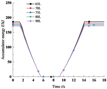
The volume is 65 L, 70 L, 75 L, 80 L, 90 L, and the pre-charge pressure is 10 MPa. Table 4 shows the simulation results of the recovered energy and the cumulative output energy of TCCBS under different volumes. The energy recycling characteristics is shown in Fig. 13(a) and the cumulative output energy characteristics of TCCBS under different volumes is shown in Fig. 13(b). The results present that the recycling energy decreases slightly with the increase of the volume. Due to the limited space for the telescopic handler to install the accumulator, the volume of the hydraulic accumulator is not too large.
Table 4The energy recovered and the cumulative output energy of TCCBS under different volumes
Volume of accumulator (L) | 65 | 70 | 75 | 80 | 90 |
Recovered energy (kJ) | 186 | 182 | 175 | 174 | 172 |
System cumulative output energy (kJ) | 310 | 311 | 313 | 314 | 315 |
Fig. 13Energy characteristics under different volumes
a) Energy recovered under different volumes
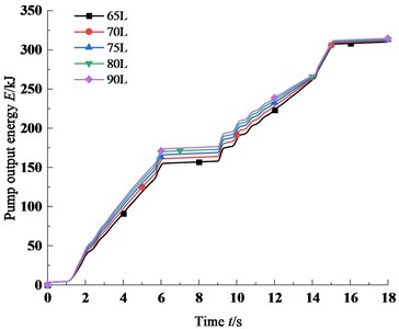
b) Cumulative output energy under different volumes
6. Conclusions
In this paper, a method for potential recycling of the working device on telescopic handler by TCCBS was proposed. Through theoretical analysis and simulation mode of DCCBS and TCCBS in AMESIM environment, the operation characteristics and energy saving characteristics of the two systems were analyzed. In addition, the influence of hydraulic accumulator parameters on energy saving characteristics of TCCBS were analyzed. The main conclusions were as follow:
1) In the TCCBS, the lifting of the boom can be achieved. Compared with the DCCBS, the single-action operation time of the boom reduced 4.15 s. The peak pressure decreased from 24 MPa to 21 MPa and the average pressure decreased from 17 MPa to 13 MPa during boom lifting process. The boom velocity fluctuation was reduced by 83.3 % at the start of the boom lowering, making the boom lower more smoothly.
2) Compared with the DCCBS, the TCCBS can achieve the direct recycling of the gravitational potential energy of the working device. The cumulative output energy of the TCCBS was reduced from 403 kJ of the DCCBS to 311 kJ. For one cycle of boom lifting and lowering, the potential energy recycling efficiency of the working device was 47.1 %, and the comprehensive energy saving rate of the TCCBS was 22. 3%.
3) The setting of hydraulic accumulator parameters has certain influence on the energy efficiency of TCCBS. When the volume was determined, the energy recycling of hydraulic accumulator increased with the increase of pre-charge pressure. However, if the pre-charge pressure was too large, the cumulative output energy of TCCBS would be too large. When the pre-charge pressure was determined, the charging and discharging energy characteristics were less affected by the volume of the hydraulic accumulator.
References
-
M. Vukovic, R. Leifeld, and H. Murrenhoff, “Reducing fuel consumption in hydraulic excavators-a comprehensive analysis,” Energies, Vol. 10, No. 5, p. 687, May 2017, https://doi.org/10.3390/en10050687
-
X. Wu et al., “Initial rotor position detection for sensorless interior PMSM with square-wave voltage injection,” IEEE Transactions on Magnetics, Vol. 53, No. 11, pp. 1–4, Nov. 2017, https://doi.org/10.1109/tmag.2017.2718025
-
D. Wang, X. Lin, and Y. Zhang, “Fuzzy logic control for a parallel hybrid hydraulic excavator using genetic algorithm,” Automation in Construction, Vol. 20, No. 5, pp. 581–587, Aug. 2011, https://doi.org/10.1016/j.autcon.2010.11.024
-
T. Lin, Q. Wang, B. Hu, and W. Gong, “Research on the energy regeneration systems for hybrid hydraulic excavators,” Automation in Construction, Vol. 19, No. 8, pp. 1016–1026, Dec. 2010, https://doi.org/10.1016/j.autcon.2010.08.002
-
J. Gong, D. Zhang, C. Liu, Y. Zhao, P. Hu, and W. Quan, “Optimization of electro-hydraulic energy-savings in mobile machinery,” Automation in Construction, Vol. 98, pp. 132–145, Feb. 2019, https://doi.org/10.1016/j.autcon.2018.08.011
-
J. Gong et al., “Power control strategy and performance evaluation of a novel electro-hydraulic energy-saving system,” Applied Energy, Vol. 233-234, pp. 724–734, Jan. 2019, https://doi.org/10.1016/j.apenergy.2018.10.066
-
T. Lin and Q. Wang, “Hydraulic accumulator-motor-generator energy regeneration system for a hybrid hydraulic excavator,” Chinese Journal of Mechanical Engineering, Vol. 25, No. 6, pp. 1121–1129, Nov. 2012, https://doi.org/10.3901/cjme.2012.06.1121
-
O. Hegazy et al., “Modeling, analysis and feasibility study of new drivetrain architectures for off-highway vehicles,” Energy, Vol. 109, pp. 1056–1074, Aug. 2016, https://doi.org/10.1016/j.energy.2016.05.001
-
L. Wang et al., “Energy management strategy development of a forklift with electric lifting device,” Energy, Vol. 128, pp. 435–446, Jun. 2017, https://doi.org/10.1016/j.energy.2017.04.012
-
H. Wang, Y. Huang, A. Khajepour, H. He, and D. Cao, “A novel energy management for hybrid off-road vehicles without future driving cycles as a priori,” Energy, Vol. 133, pp. 929–940, Aug. 2017, https://doi.org/10.1016/j.energy.2017.05.172
-
L. Ge, L. Quan, X. Zhang, B. Zhao, and J. Yang, “Efficiency improvement and evaluation of electric hydraulic excavator with speed and displacement variable pump,” Energy Conversion and Management, Vol. 150, pp. 62–71, Oct. 2017, https://doi.org/10.1016/j.enconman.2017.08.010
-
T. Wang and Q. Wang, “Efficiency analysis and evaluation of energy-saving pressure-compensated circuit for hybrid hydraulic excavator,” Automation in Construction, Vol. 47, pp. 62–68, Nov. 2014, https://doi.org/10.1016/j.autcon.2014.07.012
-
H. Kim, S. Yoo, S. Cho, and K. Yi, “Hybrid control algorithm for fuel consumption of a compound hybrid excavator,” Automation in Construction, Vol. 68, pp. 1–10, Aug. 2016, https://doi.org/10.1016/j.autcon.2016.03.017
-
T. Wang, Q. Wang, and T. Lin, “Improvement of boom control performance for hybrid hydraulic excavator with potential energy recovery,” Automation in Construction, Vol. 30, pp. 161–169, Mar. 2013, https://doi.org/10.1016/j.autcon.2012.11.034
-
X. He and Y. Jiang, “Review of hybrid electric systems for construction machinery,” Automation in Construction, Vol. 92, pp. 286–296, Aug. 2018, https://doi.org/10.1016/j.autcon.2018.04.005
-
Y.-B. Kim, P.-Y. Kim, and H. Murrenhoff, “Boom potential energy regeneration scheme for hydraulic excavators,” in BATH/ASME 2016 Symposium on Fluid Power and Motion Control, Sep. 2016, https://doi.org/10.1115/fpmc2016-1740
-
T. Lin, Q. Chen, H. Ren, W. Huang, Q. Chen, and S. Fu, “Review of boom potential energy regeneration technology for hydraulic construction machinery,” Renewable and Sustainable Energy Reviews, Vol. 79, pp. 358–371, Nov. 2017, https://doi.org/10.1016/j.rser.2017.05.131
-
J. Amrhein and U. Neumann, “PRB-Regeneration of potential energy while boom-down,” in Proceedings of the 8th International Fluid Power Conference, pp. 69–72, 2012.
-
C. Guan, M. R. Lin, C. Wu, L. Y. Zhang, and H. F. Yang, “Recovery system of boom potential energy in hydraulic hybrid excavators,” (in Chinese), Computer Integrated Manufacturing Systems, Vol. 18, No. 3, pp. 583–589, 2012, https://doi.org/10.13196/j.cims.2012.03.137.guanch.028
-
J. X. Zhu, F. P. Liu, J. L. Zhu, Q. Y. Zhang, and L. W. Chen, “Analysis and experimental study on hydraulic system work efficiency for recovering the potential energy of electric forklift,” (in Chinese), Machine Design and Research, Vol. 27, No. 6, pp. 101–104, 2011, https://doi.org/10.13952/j.cnki.jofmdr.2011.06.026
-
D. X. Zhao, M. D. Chen, Q. L. Dai, E. P. Zhang, and C. B. Xu, “System of arm potential energy recovery in hybrid hydraulic excavators,” (in Chinese), Journal of Jilin University, Vol. 41, No. 1, pp. 150–154, 2011, https://doi.org/10.13229/j.cnki.jdxbgxb2011.s1.064
-
Y. Xiao, C. Guan, and X. Lai, “Research on the design and control strategy for a flow-coupling-based hydraulic hybrid excavator,” Proceedings of the Institution of Mechanical Engineers, Part D: Journal of Automobile Engineering, Vol. 228, No. 14, pp. 1675–1687, Dec. 2014, https://doi.org/10.1177/0954407013502326
-
W. Shen, J. Jiang, X. Su, and H. Reza Karimi, “Control strategy analysis of the hydraulic hybrid excavator,” Journal of the Franklin Institute, Vol. 352, No. 2, pp. 541–561, Feb. 2015, https://doi.org/10.1016/j.jfranklin.2014.04.007
-
R. Hippalgaonkar and M. Ivantysynova, “Optimal power management of hydraulic hybrid mobile machines-part II: machine implementation and measurements,” Journal of Dynamic Systems, Measurement, and Control, Vol. 138, No. 5, pp. 1–12, May 2016, https://doi.org/10.1115/1.4032743
-
Xingui Liang, “On improving energy utilization in hydraulic booms,” Mechanical Engineering Series, 2002.
-
G. Jun et al., “Potential energy recovery method based on alternate recovery and utilization of multiple hydraulic cylinders,” Automation in Construction, Vol. 112, No. 4, p. 103105, Apr. 2020, https://doi.org/10.1016/j.autcon.2020.103105
-
L. Xia, “Research on the method of hydraulic-gas energy storage balancing hydraulic excavator boom weight,” (in Chinese), Journal of Mechanical Engineering, Vol. 54, No. 20, p. 197, 2018, https://doi.org/10.3901/jme.2018.20.197
-
L. Ge, L. Quan, Y. Li, X. Zhang, and J. Yang, “A novel hydraulic excavator boom driving system with high efficiency and potential energy regeneration capability,” Energy Conversion and Management, Vol. 166, No. 6, pp. 308–317, Jun. 2018, https://doi.org/10.1016/j.enconman.2018.04.046
-
Y. Hao, L. Quan, H. Cheng, L. Xia, L. Ge, and B. Zhao, “Potential energy directly conversion and utilization methods used for heavy duty lifting machinery,” Energy, Vol. 155, No. 7, pp. 242–251, Jul. 2018, https://doi.org/10.1016/j.energy.2018.05.015
-
L. Xia, L. Quan, L. Ge, and Y. Hao, “Energy efficiency analysis of integrated drive and energy recuperation system for hydraulic excavator boom,” Energy Conversion and Management, Vol. 156, No. 1, pp. 680–687, Jan. 2018, https://doi.org/10.1016/j.enconman.2017.11.074
About this article

This work was supported by National Natural Science Foundation of China, Grant Nos. 51875385, E050202.
