Abstract
In order to study the dynamic response of hydraulic cylinders under complex load conditions, the modal characteristics of hydraulic cylinders were simulated and calculated by comprehensively considering the combined effects of preload and oil fluid dynamics. The contact in the finite element model was specially processed to ensure that the local degrees of freedom of the piston in the structure were maintained during the modal simulation calculation process. After the static characteristics were calculated, the relevant data was imported into the modal simulation module to achieve coupling analysis under preload. By verifying the contact stiffness factor, the boundary conditions of the model were effectively optimized. The natural frequencies of the model were compared and analyzed under different piston strokes, and the mechanism of dynamic response was obtained. Through modal testing, the results indicated that the simulation results had high accuracy and reliability.
Highlights
- The modal characteristics of hydraulic cylinders were simulated and calculated by comprehensively considering the combined effects of preload and oil fluid dynamics.
- The contact in the finite element model was specially processed to ensure that the local degrees of freedom of the piston in the structure were maintained during the modal simulation calculation process.
- By verifying the contact stiffness factor, the boundary conditions of the model were effectively optimized.
1. Introduction
Hydraulic cylinder is one of the most critical components in the hydraulic system. Under harsh working conditions such as high temperature, high pressure, high speed, and variable load, it can generate various forms of severe vibration [1]. Various vibration impacts cause complex vibration responses in the hydraulic cylinder itself. Therefore, it is necessary to conduct more accurate and comprehensive research on the inherent dynamic characteristics, ensure their reliability during use, and avoid safety accidents and economic losses. At present, the research on the dynamic characteristics of hydraulic cylinders mainly focuses on free mode analysis, while there is less research on the nonlinear structural vibration of fluid structure coupling, which cannot be ignored [2, 3]. Therefore, the analysis of prestressed mode is very necessary. Based on the actual working conditions of hydraulic cylinders and considering the influence of internal oil quality and pressure, the paper establishes a fluid structure coupling dynamic model, studies the influence mechanism of contact stiffness on the freedom of movable joints, analyzes the influence of contact position and contact state on natural frequency, and verifies the accuracy of the simulation model through resonance inspection experiments [4, 5]. By analyzing the natural frequency and modal shape of components, a basis can be provided for their fault detection and structural optimization.
2. Establishment and static calculation of finite element model
2.1. Model establishment and preprocessing
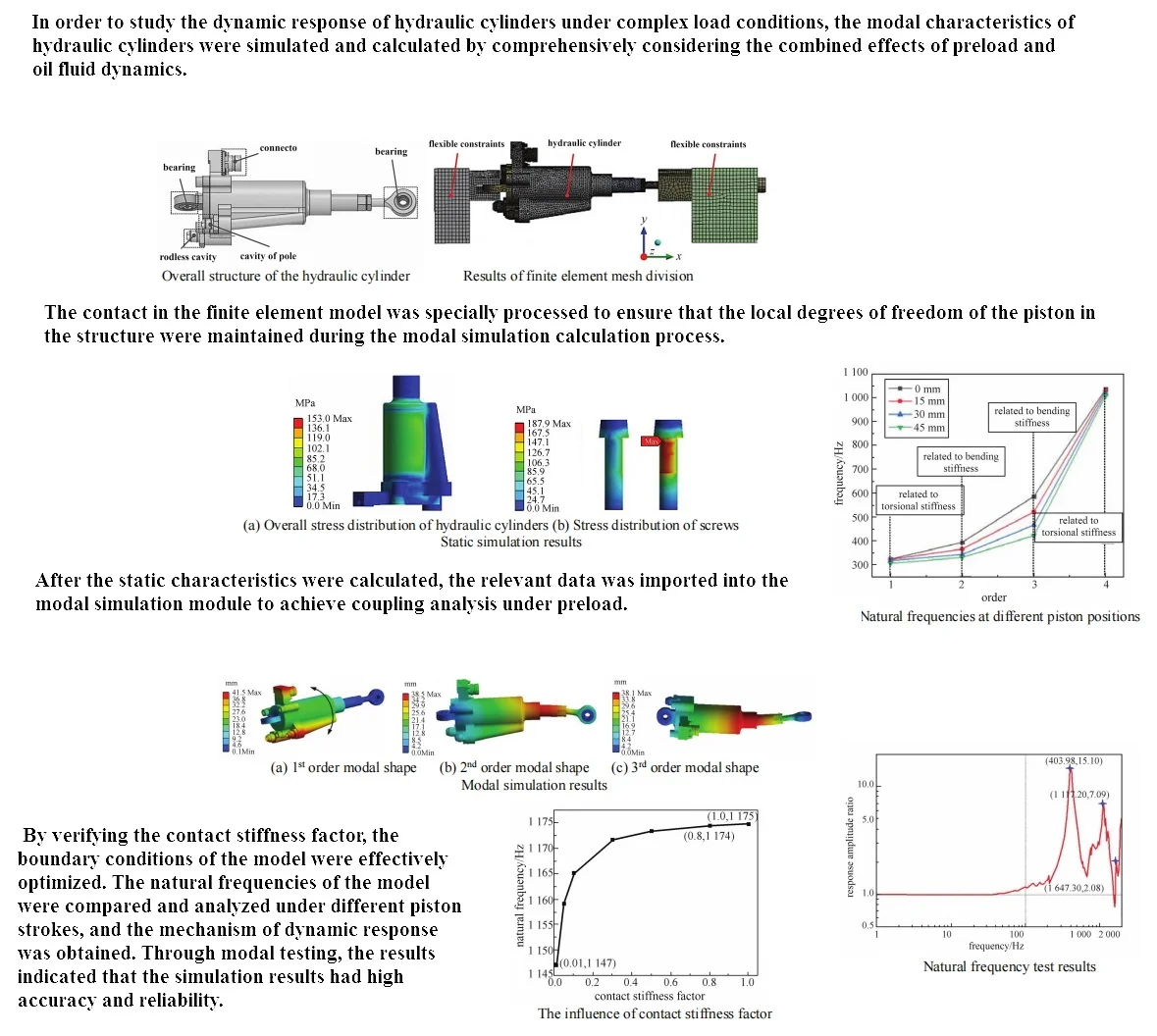
The overall structure of the hydraulic cylinder is shown in Fig. 1. It can be seen that the bottom bearing is used to fix the actuator, and the piston rod end bearing is used to output the displacement of the actuator. The integrated linear displacement sensor inside the cylinder is fixed to the connecting seat, and the piston moves together with the piston vernier and rod end bearing components. The linear displacement sensor provides feedback on the current motion status of the actuator by detecting the relative displacement of the piston cursor. The oil flow rate between the rod chamber and the rodless chamber is used to adjust the piston's telescopic position. The influence of the quality and connection stiffness of assembled components on the natural frequency needs to consider various contact behaviors between components. There are two types of contacts in the model that require special handling. A treatment involving gap contact where there is a small gap between the contact surfaces and it is necessary to ensure that the contact detection range covers the contact gap. Another type of contact that requires special treatment involves the treatment of local degrees of freedom, mainly concentrated at the contact position between the piston and cylinder. In order to ensure that the local degree of freedom of the piston in the structure is maintained during the modal simulation calculation process, relevant contact types and contact stiffness have been adjusted. In addition, connectors and contacts are combined at the connection position between the actuator and the fixture to ensure reasonable connection stiffness and avoid excessive constraints. Reasonably divide and adjust the mesh of each component, and establish a three-dimensional finite element model of the fixture actuator, as shown in Fig. 2.
Fig. 1Overall structure of the hydraulic cylinder
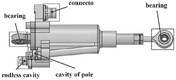
Fig. 2Results of finite element mesh division
2.2. Simulation and analysis of statics
The components of the hydraulic cylinder are mainly connected to each other through screws, and the preload will change the contact stiffness between the connecting components, affecting the natural frequency [6, 7]. Therefore, the preload should be applied according to the actual working conditions. This simulation model takes into account the impact of engine oil dynamic load, including the treatment of engine oil quality and pressure. Calculate the oil pressure distribution through a fluid solid coupling simulation model, and set the boundary conditions of the actuator under oil pressure, including an inlet pressure boundary of 12 MPa and an outlet pressure boundary of 0.2 MPa. Calculate the pressure distribution of the simulation model and import the results into the static analysis module. Considering the preload and hydrodynamic conditions, the stress distribution results are shown in Fig. 3. It can be seen that the maximum stress is much smaller than the yield strength of the material at 890 MPa. The static analysis introduces two boundary conditions, preload and oil pressure distribution, and provides fixed boundary settings to obtain stress results at stress positions, providing a basis for modal calculation.
Fig. 3Static simulation results
a) Overall stress distribution of hydraulic cylinders
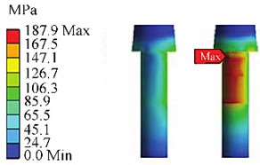
b) Stress distribution of screws
3. Simulation and analysis of modal characteristics
3.1. Natural frequency and modal shape
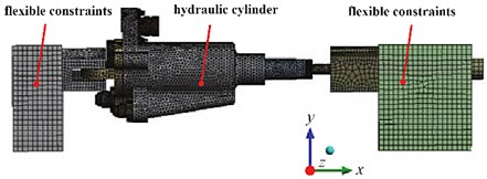
Using the results of static analysis to introduce boundary conditions as the initial conditions, calculate the natural frequency and vibration mode of the hydraulic cylinder. Considering the requirements of simulation calculation, the frequency range of modal analysis should be greater than 1.5 times the frequency of sinusoidal vibration analysis [8]. Therefore, the frequency range of simulation calculation should be set to 0-3000 Hz. The modal calculation obtains the 8th order natural frequency of the actuator below 2000 Hz, as shown in Table.1. The first three vibration modes are shown in Fig. 4. From the perspective of vibration mode, the vibration trend of the first three modes mainly occurs near the cylinder, piston rod, fixed position of bearings, and electrical connectors. The stiffness mainly involves the bending stiffness of the piston rod and the torsional stiffness of the cylinder. This finite element model obtained the dynamic response of the actuator under actual working conditions, and avoiding natural frequencies during operation can improve its service life. The adjustment method for the local degree of freedom of the piston in the finite element model can guide the vibration simulation modeling of actuator cylinder structural components with local degrees of freedom.
Table 1Natural frequency calculation results
Order | 1 | 2 | 3 | 4 | 5 | 6 | 7 | 8 |
Natural frequency / Hz | 305.6 | 411.2 | 578.9 | 1066.5 | 1184.1 | 1589.4 | 1682.2 | 1977.5 |
Fig. 4Modal simulation results
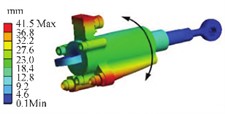
a) 1st order modal shape
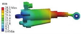
b) 2nd order modal shape
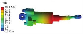
c) 3rd order modal shape
3.2. The influence of contact stiffness on torsional vibration frequency
The piston has degrees of freedom to move along the direction of travel and to twist around the axis. A purely rigid connection can result in excessive structural stiffness and inability to release the correct local degree of freedom vibration mode [9, 10]. In order to correctly map the degree of freedom of the movable parts of the piston, relevant contact parameters are adjusted to ensure that the piston produces these two vibration modes. To avoid significant contact penetration, the contact stiffness factor needs to be adjusted by using non separation contact and friction free contact between the cylinder and piston. The larger the contact stiffness factor, the greater the contact stiffness between the two contact surfaces, making it more difficult to calculate penetration between the contact surfaces, which to some extent changes the modal shape and natural frequency. By changing the contact stiffness factor for multiple sets of simulations, the impact of different contact settings on the natural frequency of torsional vibration was summarized, as shown in Fig. 5. It can be seen that when the contact stiffness factor is below 0.8, the relevant natural frequency is greatly affected by it. But after the contact stiffness factor reaches 0.8, the relevant natural frequency tends to stabilize, and there is no significant calculated penetration phenomenon from the vibration mode.
3.3. The influence of piston stroke on natural frequency
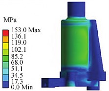
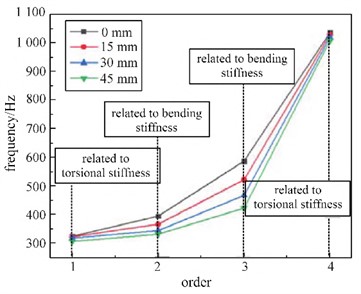
Modal simulation and calculation can obtain response information of positions that cannot be detected by experiments, such as the response information of internal positions of hydraulic cylinders that cannot be detected by sensors. On the basis of ensuring the correctness of the simulation model, more sets of different variables can be simulated and calculated. Therefore, conducting group simulation on the working conditions of hydraulic cylinder pistons at different stroke positions can obtain their natural frequency variation patterns. When adjusting the blade angle, the position of the piston on the stroke will change. For this purpose, modal simulation analysis was conducted on the piston actuator at different stroke positions. When the distance between the piston and the bottom of the cylinder is 0 mm, 15 mm, 30 mm, and 45 mm, a comparative analysis was conducted on the first four natural frequencies, as shown in Fig. 6. It can be seen that as the piston moves up the stroke, the first four natural frequencies show a decreasing trend, but the changes in the first and fourth natural frequencies are relatively small. The first natural frequency mainly involves the torsional stiffness of the hydraulic cylinder, the second and third natural frequencies mainly include the bending stiffness of the hydraulic cylinder, and the fourth natural frequency mainly involves the torsional stiffness of the piston. During piston movement, the variation in torsional stiffness is relatively small, resulting in small differences in the first and fourth natural frequencies at different piston positions. The variation in bending stiffness is relatively large, resulting in significant differences in the second-order and third-order natural frequencies at different positions.
Fig. 5The influence of contact stiffness factor
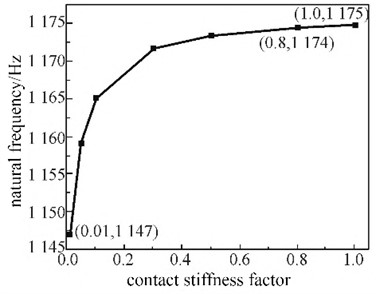
Fig. 6Natural frequencies at different piston positions
3.4. Modal testing
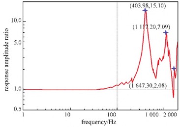
By relying on the sinusoidal excitation applied by the vibration test bench to generate a vibration environment, resonance inspection tests can be carried out on the actuator in the frequency range of 0-2000 Hz to obtain the resonance frequency that produces response peaks under working conditions. Simulate the initial working state of the piston at the 0 mm position, connect it to the bearings at both ends through the pins on the fixture, and install it on the vibration test bench. During the experiment, the chamber was filled with oil, and the oil pressure in the rodless chamber remained at 0.2 MPa, while the oil pressure in the rodless chamber remained at 12 MPa. The piston components rely on the oil pressure difference to maintain a displacement position of 0mm. Considering that the actuator structure is less prone to vibration along the piston axis in the low-frequency range, a vibration test bench is used to provide sinusoidal excitation loads along the -axis and -axis positive directions. The acceleration sensor is installed near the connection seat and outputs an acceleration response signal.
After installation, perform a resonance inspection test on the actuator, and obtain the amplitude ratio response curve of the hydraulic cylinder along the -axis and -axis through the resonance inspection test, as shown in Fig. 7. Based on the response results, extract the frequency corresponding to the peak point with a response amplitude ratio greater than 1, treat it as the resonant frequency point obtained in the experiment, and sort the frequency values from small to large. The calculated error distribution shows that the simulation error of natural frequencies below 1000 Hz does not exceed 2 %, while the error of other natural frequencies remains below 10 %.
Fig. 7Natural frequency test results
4. Conclusions
Hydraulic cylinder is a relatively complex transmission mechanism that operates under complex and variable working conditions, which can easily lead to different modes of vibration damage to the internal structure. In order to obtain the dynamic response under preload conditions, the modal characteristics of the hydraulic cylinder were simulated and tested, and the following conclusions were drawn.
1) In order to better integrate the actual working conditions, multiple factors were comprehensively considered in the simulation modeling process, and the single variable method was used to study the influence of contact stiffness factors on local degree of freedom vibration modes. When the contact stiffness factor is set to 0.8, the simulation results are the best. Considering the hydrodynamic effect of the oil and the external preload load, the modal characteristics were calculated and the position with the highest vibration trend was found from the modal shape.
2) Using this simulation model, multiple sets of simulations were conducted on the working conditions of the piston at different stroke positions. By comparing the first four natural frequencies and vibration modes, it was found that under different operating conditions, the first four vibration modes are the same, but the changes in the second and third natural frequencies are more significant. This indicates that as the piston position changes, the bending stiffness changes significantly, while the torsional stiffness changes less.
References
-
V. Nicoletti, R. Martini, L. Amico, S. Carbonari, and F. Gara, “Operational modal analysis for supporting the retrofit design of bridges,” ce/papers, Vol. 6, No. 5, pp. 1182–1188, Sep. 2023, https://doi.org/10.1002/cepa.2125
-
M. Sohrabifard, M. Nategh, and M. Ghazavi, “Evaluation, calibration, and modal analysis for determination of contact stiffness between workpiece and components of milling fixture,” Proceedings of the Institution of Mechanical Engineers, Part B: Journal of Engineering Manufacture, Vol. 237, No. 12, pp. 1819–1835, Oct. 2023, https://doi.org/10.1177/09544054221138165
-
S. de Carolis, A. Messina, and L. Soria, “Modal analysis through response-based FRFs: Additional modes for local diagnoses,” Journal of Sound and Vibration, Vol. 549, No. 1, p. 117574, Apr. 2023, https://doi.org/10.1016/j.jsv.2023.117574
-
T. Sato, M. Funato, K. Imai, and T. Nakajima, “Self-powered fault diagnosis using vibration energy harvesting and machine learning,” Sensors and Materials, Vol. 34, No. 5, p. 1909, May 2022, https://doi.org/10.18494/sam3907
-
J. Kang and S. Zeng, “Uncertainty quantification in operational modal analysis of time-varying structures based on time-dependent autoregressive moving average model,” Journal of Sound and Vibration, Vol. 548, No. 1, p. 117549, Mar. 2023, https://doi.org/10.1016/j.jsv.2022.117549
-
H. D. Chalak, A. M. Zenkour, and A. Garg, “Free vibration and modal stress analysis of FG-CNTRC beams under hygrothermal conditions using zigzag theory,” Mechanics Based Design of Structures and Machines, Vol. 51, No. 8, pp. 4709–4730, Aug. 2023, https://doi.org/10.1080/15397734.2021.1977659
-
X. Yin, Z. Huang, and Y. Liu, “Damage features extraction of prestressed near-surface mounted CFRP beams based on tunable Q-factor wavelet transform and improved variational modal decomposition,” Structures, Vol. 45, No. 1, pp. 1949–1961, Nov. 2022, https://doi.org/10.1016/j.istruc.2022.10.036
-
R. K. Bhamu, “Vibration response of steam turbine healthy and cracked blade under the stress stiffening and spin softening effects,” Proceedings of the Institution of Mechanical Engineers, Part K: Journal of Multi-body Dynamics, Vol. 236, No. 2, pp. 224–243, 2022.
-
A. Daşdemir, “A modal analysis of forced vibration of a piezoelectric plate with initial stress by the finite-element simulation,” Mechanics of Composite Materials, Vol. 58, No. 1, pp. 69–80, Mar. 2022, https://doi.org/10.1007/s11029-022-10012-7
-
J. Cui, Y. Peng, J. Sun, and B. Li, “Multi-modal stress characteristics under coupling effect of strip and work roll,” International Journal of Precision Engineering and Manufacturing, Vol. 22, No. 10, pp. 1719–1733, Oct. 2021, https://doi.org/10.1007/s12541-021-00559-1
About this article

The authors have not disclosed any funding.
The datasets generated during and/or analyzed during the current study are available from the corresponding author on reasonable request.
The authors declare that they have no conflict of interest.
