Abstract
The investigation of structure dynamic behavior can be done by finding modal properties, which are based on the relation of force and vibration response. The information about exact force value is in most application unknown, but the investigation can be done for unit magnitude of force. In case of using modal exciter, the force applied to structure is transferred by connection between modal exciter and structure. The stiffness of connection part can affect the dynamic behavior and change the modal properties, or response of investigated part, because of additional modal properties of connection part. This article is focused on the influence of two different rod stiffness during modal properties identification. The modal exciter is used to find potential critical frequency during decreasing frequency. The affect is evaluated on the surface normal velocity as well as acoustic pressure. The stiffness of rod significantly affects the dynamic response of structure and based on that can add frequency, when the emitted noise is high.
1. Introduction
The product which is designated for using at dynamics loading should be developed with regard to operating conditions. With increasing number of manufacturers, the increased requirements are placed on the final product by the customer, the manufacturer, as well as the regulations [1, 2]. The developing phase in a lot of cases consists of designing, numerical simulations and experiment [3]. These parts are connected to each other and also take a few turns. The experiment and numerical simulations are performed on couple of designs simultaneously to compare the results and validate numerical approach. The experiment has irreplaceable place in the developing phase of product as well as at validation of methodology [4].
The finding of structure modal frequency can be done by computational and experimental approach. The harmonic analysis can be performed to find the potential critical modal shapes, as a response to the known excitation. The response can be measured on the structure surface or in surroundings (acoustics) [5].
2. Methods
First, the computational approach was performed. Free oscillation of undamped system is described by matrix equation of movement:
where , resp. , is symmetric mass matrix, respectively symmetric stiffness matrix of the system. Solution of this equation has the form:
where the is a constant vector and represents the radial frequency. The second derivation of this equation has the following shape:
Substituting into the movement equation the following form is getting:
from where we get the eigenvalue equation:
in which is the eigenvalue (solution is based on characteristic equation) and w is eigenvector or “mode shape”. In technical terms it means that it is a shape that structure oscillates within the frequency .
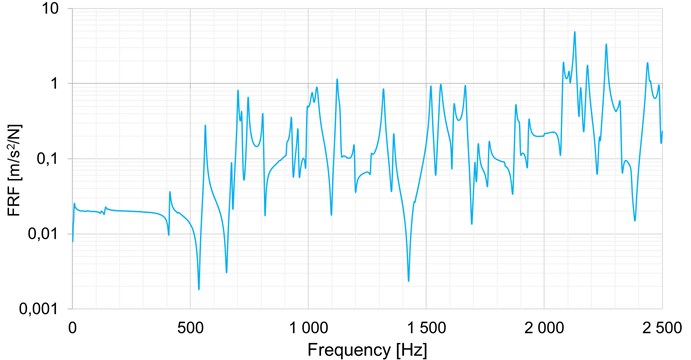
After several modifications the heavy-duty gearbox was manufactured, and the experimental modal analysis was performed. The experimental approach is based on determination of frequency response function, which is the relation between input-force and output – vibration response. The experimental modal analysis was performed by modal hammer, where the force signal was measured, and triaxial accelerometer as output function. The whole structure, in this case the heavy-duty gearbox, was suspended on the flexible rope to simulate free boundary conditions and it was measured in more than 100 points. The frequency response function, which combine the response from all point, is shown in Fig. 1. The difference between the computational and experimental approach reach 3.21 % in maximal value, the median difference is 1.56 % in range 0-2500 Hz.
Fig. 1Frequency response function of heavy-duty gearbox obtained by technical experiment
The next step was focused on the acoustics response on the known excitation. This step was performed only by experimental approach. The structure is suspended in the same way as in case of the modal analysis. The excitation is performed by modal vibration exciter and the response is recorded by microphone, for the reason that the acoustics properties are one of the key parameters of the heavy-duty gearbox. The potential structure operation conditions are in wide range, from 0 to 3000 Hz. In this case the acoustic harmonic analysis is performed from 2400 Hz to 400 Hz. Because no large initial force is required for the run-down simulation, the structure is in steady state throughout the whole experiment.
3. Results
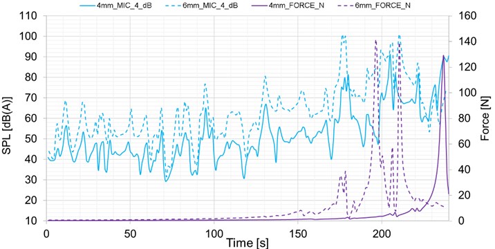
The structure was excited by two different rods, which connected the modal vibration exciter and force sensor. The force sensor was connected directly to the structure by thread. The rod is 300 mm long and has a diameter 4, respectively 6 mm. The whole measured loop was realized in the full anechoic chamber. Four microphones were measured, and the location is identical for both series of measurement. Three measurements were performed for each case with similar results. The force was also recorded for each case. The results are plotted for both rod at each microphone in separate graphs, see Figs. 2-5. The sound pressure level is weighted by A filter. The full line is for 4 mm rod and dashed line for 6 mm. The force is shown in all cases. The data are shown in time domain, but it corresponds to the frequency as well. The run-down simulation is performed from 2400 Hz to 400 Hz in 240 s, 10 Hz per sec.
Fig. 2Comparison of measurement microphone 1 for 4 and 6 mm rod
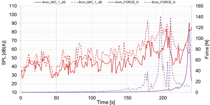
Fig. 3Comparison of measurement microphone 2 for 4 and 6 mm rod
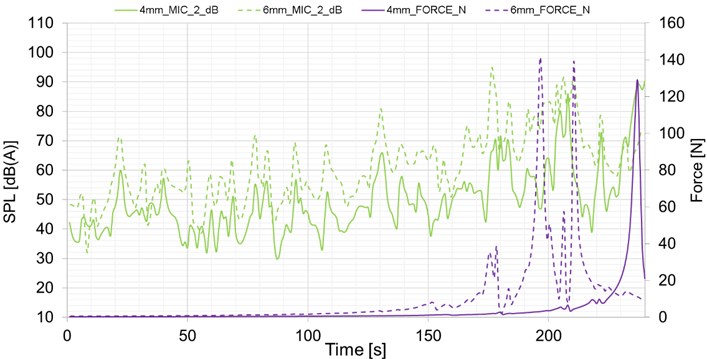
The force in high frequency reaches small difference, but with decreasing frequency the force has different peaks based on the rod stiffness. The force of 6 mm rod variant has four peaks at frequency in range 650 Hz to 1100 Hz. The force of 4 mm rod variant has only one peak at 440 Hz. The variant with 6 mm rod, which has higher stiffness, reached higher values of sound pressure level at all measured positions of microphones. The difference occurs in cases of increased levels of excitatory force, see Figs. 2-5.
First interesting frequency is at 178 s, when the variant with 6 mm rod has higher value of force, see Figs. 2-5. The sound pressure level is higher than in case of 4 mm rod. The local extreme of force is in the same time as the peaks of microphones values, thus there is no significantly change of problematic frequency.
The second peak of 6 mm rod variant is at 196 s. There is no increased value of microphone 1 and 3 at 4 mm rod variant, moreover the sound pressure level value decreased at microphone 2 and 4, see Figs. 2-5. Based on the value of 6 mm variant at microphone 1 and 3 this frequency is defined as problematic.
The third peak is located at 206 s, where the 4 mm rod variant has local low extreme. The increased value of force of 6 mm rod variant changed the sound pressure level significantly, thus based on the data from all microphones this frequency is marked as one of the problematic. On the other side there are two sound pressure level peaks at 4 mm rod variant, see Figs. 2-5.
The last peak of force at 6 mm variant is at 210 s. There is significantly changed value of sound pressure level, where this value is one of the highest from whole measurement for all microphones. The 4 mm rod variant does not have any extreme in this time at any of microphones see Fig. 2-5.
In the measured frequency range there is only one significantly force increase for 4 mm rod variant, see Fig. 2-5. It is located at time 237 s, where the sound pressure level reaches highest value. The 6 mm rod variant does not have any extreme in this location at any of microphones.
Fig. 4Comparison of measurement microphone 3 for 4 and 6 mm rod
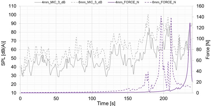
Fig. 5Comparison of measurement microphone 4 for 4 and 6 mm rod
4. Conclusions
The harmonic acoustics analysis is widely used at application, where regulations limits exist. The component testing is often performed using modal vibration exciter. The connection is realized by rod, which is placed between force sensor and exciter. Despite the rod is located outside the transfer path, the acoustic measurement can be affected. For that reason, two different measurement were performed, where only rod diameter was changed from 4 to 6 mm. The force of each variant is significantly different. Based on this difference the sound pressure level is changed in the extreme force location. Based on the results the rod significantly affects the sound pressure level value. If the new structure is tested, the influence of the rod should be investigated to avoid local increase of force values in measured range, thus detect wrong maximal location of sound pressure level of structure.
References
-
Kadmiri Y., Rigaud E., Perret-Liaudet J., Vary L. Experimental and numerical analysis of automotive gearbox rattle noise. Journal of Sound and Vibration, Vol. 331, Issue 13, 2012, p. 3144-3157.
-
Kumar A., Jaiswal H., Jain R., Patil P. P. Free vibration and material mechanical properties influence based frequency and mode shape analysis of transmission gearbox. Procedia Engineering, Vol. 97, 2014, p. 1097-1106.
-
Prokop A., Zubík M., Řehák K., Novotný P. Approach for assessment of experimental gearbox NVH parameters. Frontiers of Manufacturing Science and Measuring Technology V, 2015, p. 266-271.
-
Řehák K., Prokop A., Zubík M., Novotný P. Investigation of single stage gearbox parameters influencing surface normal velocity. Engineering Mechanics, 2016, p. 478-481.
-
Tůma J. Vehicle Gearbox Noise and Vibration. Wiley, Chichester, 2014.
About this article
The research leading to these results has received funding from the Ministry of Education, Youth and Sports under the National Sustainability Programme I. (Project LO1202) and with help of the project FSI-S-17-4104 granted by specific university research of Brno University of Technology. The authors gratefully acknowledge this support.
