Abstract
This work presents the development of a methodology that, through the use of the coordinate transformation method, identifies the ideal modal parameters that should be used during the modal balancing process as well as allows eliminating the computational modes generated during the rotor response diagram extraction process. There is currently a wide variety of methods for structures that allow extracting limited modal parameters, such as: previous knowledge of the number of modes, adjustment of computational or spurious modes, close mode identification problems, and others. However, localizing the phase angle in rotation systems in any angular position and through complex coupling of the vibration modes does not ensure that the methods developed for structures conserve the same performance during the adjustment process. As regards the line of investigation into modal balancing, a method is proposed that allows ensuring that the modes found are real modes of the system and that through direction tracking where a single vibration mode is excited, the optimum extraction position of the modal parameters used in the balancing process can be determined. The proposed methodology was developed using a linear model and was applied in a field turbogenerator to identify the vibration modes present in the response diagrams.
1. Introduction
The balancing process is critical to ensuring that rotating machinery operates within a safe vibration range. Misalignment and mass imbalance are the main causes of high vibration problems [1]. The influence coefficients method, the modal balancing technique, and a combination of both have been developed for the field rotor balancing process.
The objectives of the balancing process are: 1) to decrease the unavailability of machinery in the balancing process; 2) to save energy by improving the number of iterations in the balancing process; 3) to increase the useful life of the rotating machinery; 4) to eliminate damage caused by the high levels of vibration; and 5) to generate the detection of different types of problems in the rotation systems that can be hidden by vibration as presented in [2]. A good description of the balancing methods and their evolution is reported in [3] and references therein.
One of the advantages of the modal balancing method is that it can be applied to a single mode at a time or to multiple modes without affecting modes that have already been balanced. Bishop [4] developed the movement equations using the analogy between a conical pendulum and a rotor with a constant diameter, using the principal modes term to model the vibration in shafts without damping. The term “modal balancing of rotors” was first introduced in [4] and in subsequent papers. Gladwell & Bishop [5] extended the study to a rotor with a non-constant diameter. The natural frequencies and characteristic functions of the system were also presented in [5]. The mathematical basis of the modal balancing method for systems with constant and non-constant diameters can be found in [4, 5]. Furthermore, the modal techniques for balancing flexible shafts have been established in references [4-6]. The restrictions in modal balancing for practical shafts rotating in asymmetric bearings were relaxed by Parkinson [7]. The balancing procedure for large flexible shafts, considering two principal flexure planes in the system, was also proposed in [7]. The authors of [7] proposed the concepts of “principal damping planes” and “principal flexure planes,” also suggested that these planes could be different. In [8], a modal balancing method without trial runs was presented and applied for the balancing of one mode in an industrial compressor. Aguirre [9] studied a special case in rotodynamic systems when the maximum vibration amplitude and the phase lag are not perpendicular and could be a source of error in the modal balancing process.
Recently, a general procedure using modal analysis for the balancing of a flexible rotor, which can be applied to a single mode, was described in [10]. According to [10], using the proposed method generates an unbalanced residue due to the modal coupling effects. In addition, an angular error in the localization of the shaft mass, caused mainly by a deviation between the angular position of the transducer and the Principal Axes of Stiffness (PAS), is reported in [11].
Despite the multiple studies reported in the literature, systematic implementation of the modal balancing process continues to be an unsolved problem. Currently, there are several limitations for the practical implementation of the modal balancing process, such as:
1. The excess of information provided by the transducers of a rotodynamic system. The analysis process in the field may be difficult for a large amount of collected data.
2. Inaccuracies in the extraction of the modal parameters for the calculation of the correction weights and their angular positions. Ramp accelerations, non-linear effects, fitting errors in the extraction tool, or interaction between different vibration modes can cause the aforementioned inaccuracies.
3. Coupled vibration modes can cause difficulties for the interpretation and extraction of the modal parameters.
In this work, a new methodology for the practical implementation of the modal balancing process was developed in order to overcome the aforementioned shortcomings. The basis of the proposed method is the identification of both the vibration modes and the principal axes of stiffness. The developed methodology also improves identification of the vibration modes and their optimum modal parameters extractions, simplifying the polar response diagrams. Finally, validation of the studied methodology is presented through its implementation in the analysis of a large practical rotor.
2. Frequency methods for identifying modal parameters
For decades, curve adjustment methods have been developed and improved for the extraction of modal parameters from the response diagrams of mechanical systems, mainly applied to structures (civil engineering and aeronautics). The methods developed for curve adjustment are mainly the mode-by-mode and multiple mode approaches. In Ewin [16], the main methods used for the mode-by-mode approach are presented, for example, the circle adjustment method, the peak amplitude method, the residues method, and others, while the Non-Linear Least-Square (NLLS) and the Rational Fraction Polynomial (RFP) methods are presented for multiple mode adjustment, in addition to global adjustment methods through the use of the Single Value Decomposition (SVD) technique. Authors such as Richardson have worked for decades on improving these techniques, mainly using the RFP method, as presented in [18]. A comparative approach between the different methods presented in [16] has been difficult to obtain; however, an effort toward this was presented by Lee and Richardson in [19], where RFP was evaluated for the mode-by-mode and multiple mode approaches. It was concluded that the simultaneous mode adjustment approach generates the best behavior under the different analysis conditions.
However, in rotation systems, the phase angle present in each mode can be found in any angular position in the range of 0-2, so coupling between modes become an additional complex problem to be resolved, unlike in structures where the phase angles are aligned or displaced 180°.
Renowned authors in the area of modal balancing, such as Bishop in [20], present information on methods utilized to manually extract balancing parameters, which are the peak amplitude and circle adjustment methods. In 1982, Palazzolo and Gunter presented, in [21], a balancing method without test runs, using the circle adjustment method with the mode-by-mode approach to extract the necessary parameters and apply them to field turbine balancing. The same method used in [20, 21] was applied in [14, 22]. Wing, in [23], utilized the polynomial adjustment method presented by Ewin in [16] to obtain the parameters necessary to carry out the balancing of a test rotor with two vibration modes.
The above methods have the disadvantage of requiring prior knowledge of the number of modes present, which can generate spurious, or computational, mode adjustments. To first estimate the number of modes present in a Frequency Response Function (FRF), there are methods such as SVD, presented in [19], as well as the methods presented in [16], such as the Mode Indicator Functions (MIFs) or the Modal Assurance Criterion (MAC) presented in [24, 25]. However, these methods allow estimating the approximate number of modes, but do not completely avoid computational mode adjustments.
3. Principal axes of stiffness and modal balancing
By definition, the Principal Axes of Stiffness of a vibration mode represent the direction a specific force can be applied to obtain a displacement in the same axis. According to [12, 13], the coupling of the vibration modes into the dynamic response of a shaft is not inherent to the system, but rather depends on the implemented coordinate system.
Fig. 1Simplified model of a 2 DOF rotor with non-perpendicular PAS
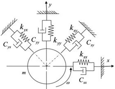
A system of 2 degrees of freedom (DOF) can be observed in Fig. 1. Applying Newton’s second law to the system in Fig. 1 and rearranging in matrix form, the following equation can be obtained:
In Eq. (1), is the total mass of the rotor, , are the direct coefficients of viscous damping, , the cross damping coefficients, , the direct stiffness coefficients, , the cross stiffness coefficients, and is the imbalance force.
The solution of Eq. (1) is the vibration amplitude in the x and y axes of the system. However, in practical implementations, the coefficients are not usually equal to zero. The coupling of two vibration modes can be observed for the and axes of the system. Applying a coordinate transformation to Eq. (1), it is possible to find an angular position on the new axes and , where at least one of the coefficients will be equal to zero.
Assuming that the PAS is coincident with the principal axis of damping (PAD), and that the principal directions are perpendicular, we can obtain:
In Eq. (2), the vibration modes on axes and are uncoupled. If a transducer is located on the axis, a single vibration mode will be observed. Therefore, the identification of the vibration mode is simple and the optimum modal parameters over the axis can be extracted. The PAS and the PAD are not commonly perpendicular in practice. For this research, systems with non-perpendicular PAD are studied, assuming that PAS and PAD are coincident.
Theoretically, a 90° lag between the system response and the imbalance force occurs when the shaft operates at its natural frequency. This lag also occurs in rotors with asymmetric bearings when the vibration transducer is located in a PAS of the vibration mode as shown in [17]. Also, asymmetric bearings have a coupled mode in horizontal and vertical directions, as presented in [17]. In the previous spatial linear analysis, the gyroscopic effects are not considered, since these effects do not affect the methodology proposed in this work.
The response of a flexible rotor can be expressed as a series of characteristic functions and principal coordinates:
where is the number of vibration modes, is the th principal coordinate and is the th modal form of a vibrational system without damping. The characteristic function represents the shaft deformation in the th vibration mode with a natural frequency of .
The vibration amplitude caused by the unbalanced modal component at a certain angular position is given by:
where is the ratio between the r-ith natural frequency and the rotation frequency of the system, is the th damping ratio, and is the amplification factor.
To eliminate the centrifugal forces generated by the th eccentricity component, different masses must be added to the system in order to achieve rotor balance in the th vibration mode. Assuming a balancing plane located in , the correction mass can be obtained by:
where is the modal mass observed in the reference position of the transducer and the balancing plane radius. In resonance ( 1), the amplification factor of the system is:
Substituting Eq. (6) in (5), the correction mass is given by:
The discrete form of the modal mass in the position of the reference transducer can be obtained with the following equation:
In the system under study, the vibration amplitude, damping ratio, natural frequency, and phase angle are parameters obtained via experimental measurements. However, the development of mathematical models for the accurate estimation of modal forms is highly difficult.
4. Coordinate transformation
As stated in Section 3, the dynamic response of a shaft is not inherent to the system, but rather depends on the implemented coordinate system. For this reason, it is possible to generate signals for imaginary transducers located in any direction given by the analyst by performing a coordinate transformation on the available measured signals.
The expression:
can be obtained from Fig. 2, where:
Fig. 2Referential coordinate system
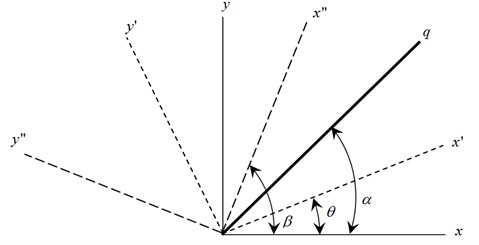
Eq. (10) represents an imaginary transducer that senses the system’s movement from any direction, starting from any pair of signals from that movement. The new axes , and , have a perpendicular condition and and directions represent the signals of physical transducers located on the bearing. and are the sine and cosine components, respectively, of a signal obtained in the direction , while and are obtained in the direction of the new axis .
Eq. (9) represents an imaginary transducer that senses the system’s movement from any direction, starting from any pair of signals from that movement, and this equation characterizes the coupling of the vibration amplitudes , generated on the PAS. A similar expression and its experimental corroboration can be found in [14].
In order to estimate the maximum vibration amplitude of a specific mode, determination of the phase angle is needed. Phase angle determination requires the value, in which the first derivative of displacement vanishes with respect to time, resulting in the following expression:
where is the system response lag with respect to the excitation force.
Rearranging Eq. (9), the following can be obtained:
Assuming perpendicular PAS, 90°, then:
From Eq. (13), a period of the signals ( and ) can be obtained. A sinusoidal variation of the vibration amplitude with respect to the difference between the mode’s PAS and the angular position of the vibration transducer can be seen. Also, the amplitude variation in Eq. (13) represents the characteristic pattern for the vibration mode presented in Fig. 3.
Fig. 3Characteristic patterns in displacement of Eq. (13)
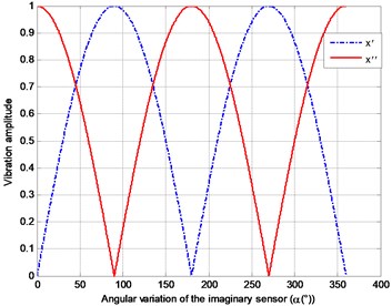
In this special case, the maximum vibration amplitude occurs only in perpendicular condition, as noted in [7], where the principal flexure planes are coincident with the horizontal and vertical axes.
If the PAS are coincident with the x and y axes from Fig. 2, then 0°, 90°, and Eq. (13) can be rearranged as:
In Eq. (14), the signal from the imaginary transducer contains the coupling of both vibration modes. However, if the position of the imaginary transducer is coincident with the horizontal PAS, then 0°; for that particular case:
The imaginary transducer is detecting only the contribution of the mode in that direction. Due to the isolation of the mode, the optimum modal parameters must be extracted in that particular direction. As can be observed in Eq. (5), the vibration amplitude directly affects determination of the balancing weight value.
From Eq. (3) it can be demonstrated that when placing the imaginary transducer at an angle of 90° with respect to the direction or , the phase angle is independent from the angular position of the transducer.
The graphical representation of Eq. (11) implies that when the angular position of the bearing transducer changes, the phase angle remains constant. With a constant phase angle there is only one correct position of the transducer for its proper determination as shown in [11, 14]. This position is known as the principal axes of stiffness (PAS). A proportional error in the location of the correction mass will be generated at any different position of the transducer.
5. A new methodology for the modal parameter identification process
A new methodology was developed using Eq. (9) along with a modal parameter extraction tool and a 2D plotting function. The determination of the PAS in the bearings provides the following advantages:
• It helps to identify the vibration modes in the response diagrams used for the modal balancing process.
• It improves interpretation of the response diagrams for locating the PAS in the bearings.
• It estimates the optimum modal parameters for the modal balancing process.
• It eliminates the phase angle error.
If the methodology is applied to an n-bearings turbogenerator, the sub-equipment in resonance condition can be identified. Additionally, the maximum amplitude of the vibration modes can be detected in every sub-equipment in resonance, improving vibration mode detection. The developed methodology is described below.
5.1. Initial conditions
1. Signals from two vibration transducers at different locations on the bearing (with a non 180° relationship between them) are needed. This will avoid the use of redundant information in the imaginary sensor.
2. The signals from the vibration transducers must be from the same trial run and rotating frequency.
3. A numerical analysis must be performed according to the type of signal, damping, and excitation force. Working with rotation systems where the excitation force is due to an imbalance when measuring the vibration amplitude in displacement, velocity, or acceleration, the maximum vibration amplitude does not occur with a 90° displacement in the dynamic response of the system. This problem is presented in [8, 9], where the initial research proposed expressions to carry out the corresponding correction. Researchers such as Preciado [14] and Aguirre used a different technique consisting of performing an integration of the displacement signal:
where and are the integrated displacement signals obtained from the sensors (commonly located at 45° and 135°) placed on the bearings, where the term represents the numerical manipulation carried out on the signal data or . It is important to note that not only is the vibration amplitude affected, but there is also a 90° discrepancy with respect to the original signal. For cases where the signal obtained from the vibration transducers is velocity or acceleration, a second and third integration is performed.
4. For development of the methodology, only forces and vibrations generated by the imbalance are included in the numerical model.
5.2. Methodology
1. To begin the analysis, two response diagrams of the sensors placed on a bearing are required, as shown in Fig. 5, with identifying an angular position of and at degrees; the equation of the imaginary sensor (Eq. 9) is applied, generating synthetic signals at 360° of the bearing. This generates variations in the response diagrams for each angular position , as seen in Fig. 6. At this stage, it is important to consider that the modal parameters must be extracted from each synthetic signal, so an elevated number of these will increase the time required for mode adjustment and extraction.
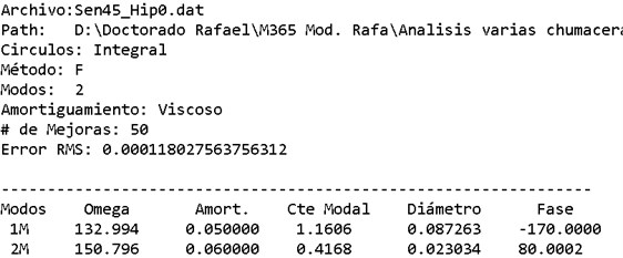
2. Then, a modal parameter extractor (MPE) must be used to adjust the vibration modes of each synthetic signal obtained. The authors recommend the mode-by-mode approach, as in their experience with rotation system response diagrams, they have found that the apparent phase of a coupled mode can have a significant variation with respect to the same mode when uncoupled, in turn affecting the vibration amplitude. In the present work, the circle adjustment method presented in [16] was used to extract the modal parameters. One example of this is shown in Fig. 4.
Fig. 4Modal parameters extracted from a synthetic signal at 0°
3. The modal parameters , , , are plotted against the angular variation of the imaginary transducer for each pair of modes in order to generate the characteristic pattern. These patterns allow explicit identification of a frequency uncoupled vibration mode. As shown in Eq. (11), the phase angle is independent of the angular placement of the sensor, as are the natural frequency variables and the damping ratio. However, the vibration amplitude depends on the position of the vibration sensor. Using this information jointly, the characteristic patterns are presented in Figs. 7 and 8.
To determine the optimum position for extracting the modal parameters to be used during the modal balancing process, the main stiffness directions must be located. This can be done in one of two ways: using the characteristic pattern of the phase angle or the vibration amplitude. To identify these directions, a pair of modes is required (commonly denominated horizontal and vertical modes.)
4. PAS identification using the vibration amplitude.
• The characteristic pattern can be represented by a rectified sinusoidal signal for each vibration mode, as presented in Eq. (12)) and Fig. 3.
• The PAS of a vibration mode can be found in the angular position, from the vs graphic, where the vibration amplitude of their pair is zero.
• It should be noted that the maximum amplitude of a specific vibration mode is 90° ahead from the direction where its amplitude is zero. This characteristic variation of a mode helps us to improve detection of the position where the contribution of a single mode disappears from the total response of the system. Also, the error in the MPE process regarding the maximum vibration amplitude is reduced. Hence, the PAS of a mode’s pair can be obtained locating the position where . In cases where only one mode is located in an analysis, it is recommended to assume perpendicularity between the PAS’s, finding that the maximum vibration amplitude of the characteristic pattern coincides with the PAS of the mode.
5. PAS identification using the phase angle.
• Due to the phase angle being independent from the angular variation of the imaginary transducer, the characteristic pattern is a constant line for a specific range. However, according to the coordinate system used, each vibration mode exhibits a 180° angular change, detected by the imaginary transducer. Finally, the PAS of the pair mode can be found in the intermediate position, where this change occurs.
Once the PAS’s for each pair of modes have been identified, they will be used to extract the optimum modal parameters that must be used during the balancing process.
The methodology above can be applied for the analysis of one rotation system bearing. In practice, the analysts use several response diagrams from the different transducers on the bearings. The same principle is used in this work to develop the identification methodology that can be applied in an n-bearing turbogenerator.
The following additional advantages can also be obtained:
• Identification of the equipment in resonance can be achieved, relating to the corresponding natural frequency and modal form.
• The partial modal shape for each point corresponding to the bearings where the transducers are located can be obtained using the PAS location.
• Twisted modes can make the PAS of each pair of modes in a bearing different.
6. Experimental results
To demonstrate the reliability of the methodology, a linear numerical model of a turbogenerator with 14 coupled vibration modes was used, as shown in [15]. For the case study in this article, only two vibration modes were used, where separated natural frequencies were considered. The parameters used – natural frequencies, (viscous) damping ratio, and Principal Axes of Stiffness – are shown in Table 1.
Table 1Modal parameters for the generation of the system’s dynamic response using SI units
Mode | (rpm) | (°) | PAS (°) | |
1 | 1270 | 0.05 | 170 | 10 |
2 | 1440 | 0.06 | 100 | 80 |
Imbalanced mass: 200 grs at 0° Radius: 0.45 mts | ||||
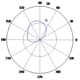
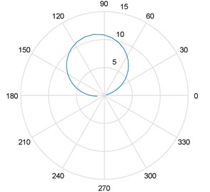
With the above parameters, the dynamic response was generated for each of the bearings of interest, and considering that a sensor at 45° and 135° is located in the bearing, the corresponding polar diagram was obtained, as shown in Fig. 5.
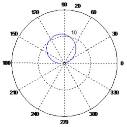
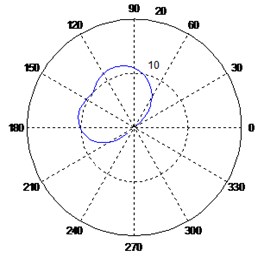
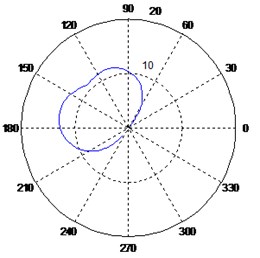
The results from Fig. 5 are used to generate an number of synthetic signals as described in step 1 of the previously described methodology. This step will generate a new polar response diagram for each angular position selected, as shown in [17]. For this case study, the synthetic polar diagrams are presented, considering the range of 0 to 50° with 10° increments in the imaginary sensor, as shown in the figure below. For pattern generation, the range was from 0-2 with 10° increments.
Following step 2, the modal parameters of each polar diagram are obtained. In the present research, the circle adjustment method presented in [16] was used, applying the mode-by-mode approach. With the parameters of , , , adjusted, these are graphed with respect to the variation of the imaginary sensor, generating the patterns shown below.
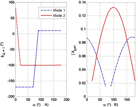
The PAS can be found by applying step 6 of the developed method. For the results shown in Fig. 8(a), the PAS is located at the directions of 10° and 80°.
Fig. 5Diagram response for two vibration modes (vibration amplitude in μm). Sensors at: 45° and –45° with respect to the vertical axis
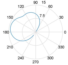
a) Sensors at 45°
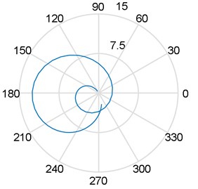
b) Sensors at –45°
Fig. 6Variation of the polar response diagrams with respect to the imaginary sensor
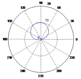
a) Sensors at 0°
b) Sensors at 10°
c) Sensors at 20°
d) Sensors at 30°
e) Sensors at 40°
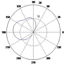
f) Sensors at 50°
In practical implementations, the use of the vibration amplitude vs plot (Fig. 8(b)) is the best way to identify the PAS, by performing step 5 of the proposed methodology.
Finally, in order to estimate the optimum modal parameters with the known PAS, steps 7 to 10 of the proposed methodology were implemented. The results obtained are presented in Table 2.
From the results in Table 2, it can be seen that the estimated optimum modal parameters agree well with the parameters from Table 1. Here, an error of less than 0.04 % in the phase of mode 2 was achieved. The pair of modes was identified using the characteristic patterns, and the optimum modal parameters were used for the modal balancing process. Additionally, correct identification of the PAS allows allocation of the balancing mass without angular error, unlike in the results presented in [14]. This demonstrates the reliability of applying the proposed methodology when there are separate natural frequencies in the vibration modes when using the linear model. In addition, it can be seen that this methodology avoids identification of computational modes and the use of methods for determining the number of modes present in the polar response diagram.
Table 2Optimum modal parameters estimated using the proposed methodology
Mode | (rpm) | (°) | (μm) | |
1 | 1270 | 0.05 | 169.97 | 11.07 |
2 | 1440 | 0.06 | 100.04 | 18.80 |
Fig. 7a) Characteristic pattern of the natural frequency according to α, b) characteristic pattern of the damping ratio according to α
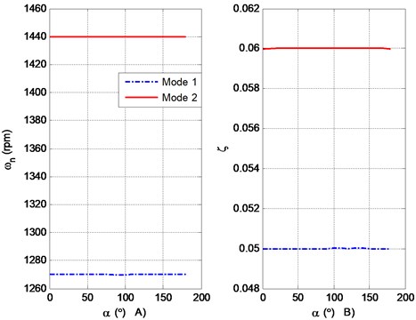
Fig. 8a) Characteristic pattern of the phase angle according to α, b) characteristic pattern of the integral of the vibration amplitude according to α
The circle adjustment method through the mode-by-mode approach was used in this methodology. When used in isolation and applied directly in response diagrams to sensors placed at 45° or 135°, numerical values will be obtained, where the vibration amplitude would have components of the two modes, reflected in a correction mass calculation whose error will be proportional to the amplitude component of the mode that is not to be balanced. The phase angle is the other parameter where an error is generated in the angular placement of the balancing mass, and which will be proportional to the angular difference between the main direction of the mode to be balanced and the placement of the vibration sensor, as shown in [14, 17, 26].
It should be noted that the integral symbol in the caption of the vertical axis in Fig. 8(b) denotes that, due to an excitation caused by an imbalance, the maximum vibration amplitude in displacement does not correspond with the resonance and neither has a 90° lag. Ignoring this condition during the modal parameter extraction process will generate errors in the estimation of vibration amplitude and phase angle.
The authors of [14, 17] propose a numerical processing consisting of the integration of the displacement vibration signal, assuring that the maximum vibration amplitude has a 90° lag with respect to the imbalance force. The proposed integration implies that the signal from the displacement sensor must be multiplied by the inverse of the rotation velocity. However, the result of the numerical processing has no physical meaning, since it has units of vibration amplitude/rotation velocity; thus, to be able to use the generated data, the inverse process is needed once the corresponding modal parameters are obtained. The inverse process is obtained by multiplying the results in Fig. 8(b) by the rotation velocity of the system. By integrating or deriving the vibration amplitude, a 90° lag is introduced into the results. Previous work reported by Palazzolo [8] presents a complex method for estimating the location of the vibration amplitude of the displacement. However, the method proposed in [8] does not solve the errors in the modal parameters extraction process. In Table 2, the transformations of the phase angle and the vibration amplitude for the specific values of interest are shown in the original displacement units.
From the analysis of the vibration amplitude in Fig. 8(b), it should be noted that only in the PAS directions (10° and 80°) is a single mode isolated (see Fig. 9).
Fig. 9One mode isolated on the PAS. Imaginary sensor q on the PAS (α= 10°)
From a practical point of view, a reduced number of modes help the modal balancing specialist to better interpret the polar graphics (or Bode diagrams). When the different bearings on a rotor have the same Principal Axes of Stiffness, a reduction of 50 % in the number of modes is achieved by implementing the proposed methodology.
Although the methodology was developed for the optimum determination of the modal parameters, it can also be implemented for the identification of vibration modes in diagnostic applications. To validate the robustness of the method, the proposed methodology was implemented to analyze an industrial turbogenerator in order to diagnose its operation state.
The analysis was performed assuming viscous damping in the 8 bearings of the turbogenerator. In the present work, only the mode corresponding to the electric generator – in bearings 7 and 8 – is reported (see Figs. 10 and 11).
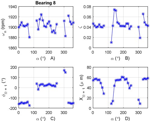
The same vibration mode shown in Fig. 10 was found in bearing 8.
From the analysis of Figs. 10 and 11, a 180° phase change can be observed between bearings 7 and 8. The phase change corresponds to the second modal form of the electric generator’s mode. In this particular case, the PAS is assumed to be perpendicular for the determination of the modal parameters (see Table 3).
From Fig. 10(d), it can be seen that the vibration amplitude from the displacement transducers is below the limits presented in the ISO 7919-2 standard.
Table 3Modal parameters calculated in the electric generator
Bearing 7 | Bearing 8 | ||
Viscous damping | Viscous damping | ||
Mode 1 | (rpm) | 1903 | 1909 |
PAS (°) | 50 | 20 | |
(r) | 53.2 | –144.8 | |
0.03 | 0.04 | ||
(μm) | 25.41 | 57.35 | |
Fig. 10a) Natural frequency variation according to α for bearing 7, b) damping ratio variation according to α for bearing 7, c) phase angle variation according to α for bearing 7, d) vibration amplitude variation according to α for bearing 7
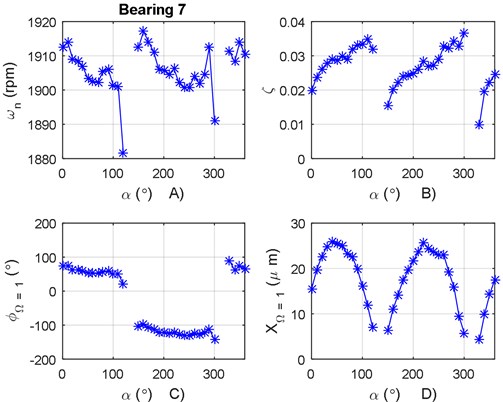
Fig. 11a) Natural frequency variation according to α for bearing 8, b) damping ratio variation according to α for bearing 8, c) phase angle variation according to α for bearing 8, d) vibration amplitude variation according to α for bearing 8
7. Conclusions
There are currently different methodologies in frequency for the adjustment of vibration modes in a response diagram for structure analysis, which mainly present limitations such as identification of spurious, or computational, modes or problems in identifying close mode frequencies, as well as the need of a priori knowledge of the modes present in the response diagram. On the other hand, the phase angles of the different modes in structures are in the same direction or displaced 180° and unlike in rotation systems, the phase angle can be in any angular position, which complicates the modal parameter extraction process. In addition, there is currently no comparative evaluation of the efficiency of the methods developed for structures and applied to turbomachinery, with which the behavior presented in the first systems could not be preserved.
On the other hand, modal balancing does not systematically apply in the field, despite decades of corresponding mathematical development. This is due to different limitations, such as those presented in the introduction of this article and in [11, 17].
In this work, a new methodology was proposed for optimum modal parameter identification used for the modal balancing process with frequency separated modes.
The proposed methodology allows eliminating the presence of computational modes through patterns found for each frequency separated mode, avoiding having to know the number of modes a priori when relying on the mode-by-mode approach through the circle adjustment method. These characteristic patterns were largely determined by applying the imaginary sensor technique to the signals originating from the vibration sensors located on a bearing, so this advance in identification allows ensuring the presence of a real mode and being used for balancing or for diagnostic purposes, as was the case in the field study presented in this article.
As regards modal balancing, the angular placement of the sensor where the parameters used are extracted for the correction mass calculation becomes fundamental, due to how the vibration amplitude varies according to the angular placement of the sensor around the bearing. Therefore, locating the directions where the modal parameters that excite only the mode to be balanced are extracted becomes a challenge. This last part of modal balancing has been little studied, as the errors produced through its application are considered to be products of faults in the adjustment process, non-linearities of the system, or problems in the acquisition process and vibration data processing, among others. Even when the above factors contribute to increasing the number of runs during modal balancing, not having the modal parameters that excite only the desired vibration mode or placing the correction mass without considering the main stiffness direction can significantly contribute to the need for more than one run in order to carry out this balancing method in a practical manner.
The proposed methodology allows identifying the PASs – the unique positions where a single vibration mode is excited and which represent the optimum place for extracting the modal parameters to be used for the balancing process. Additionally, this information allows correcting the placement angle of the balance masses, as the angular position of the PAS with respect to the horizontal of the diagram must be considered. There is visual support for specialists during the balancing process in the response diagrams used, as when observing them in the identified PASs, they can significantly reduce the coupled modes present (in cases where the main directions for horizontal/vertical modes are the same, there is a 50 % reduction when observing only the modes in that direction.)
Modal theory considers modal forms to be flat in their mathematical development. However, there is research into turbomachinery that discusses twisted modes, and from more than 30 years of experience by the thesis director of this work in field balancing, there is evidence that modal forms can be totally flat or not; however, there is no methodology that allows identifying this problem in a field rotor, nor has the degree of impact it has on the modal field rotor balancing with twisted mode forms considering flat modal forms been evaluated.
Contributing to this area of modal balancing, when applying the proposed methodology in each of the bearings installed along the rotation system and identifying the PASs of each vibration mode, locating a difference between the PASs of one mode is indicative of the possible presence of a twisted modal form.
The proposed methodology was applied to an industrial turbogenerator for diagnostic purposes, starting from the vibration analysis.
One of the main problems for the data analysis process was the low vibration levels. The measured vibration is within the range established by the ISO 7919-2 standard, where noise has a large effect on low level vibration. Another problem was the high run-out levels in some signals.
From the analysis process of the turbogenerator’s experimental data, it was possible to obtain the modal parameters from the second vibration mode of the electrical generator. The natural frequency of the identified mode occurs at 1900 rpm, near the operational velocity of the machine (1800 rpm).
Finally, implementation of the proposed methodology for the analysis of an industrial system aids in the validation of the characteristic patterns obtained in the theoretical model.
References
-
Gunter E. J., Barret L. E., Allaire P. E. Balancing of multimass flexible rotors. Proceedings of the 5th Turbomachinery Symposium, Turbomachinery Laboratory, Texas A&M University, College Station, Texas, 1972.
-
Guerrero L. J., Guerrero C. G., Muñoz V. J. Metodología de balanceo en la Comisión Federal de Electricidad: doce años de desarrollo. Boletín IIE, Vol. 17, Issue 1, 1993.
-
Foiles W. C., Allaire P. E., Gunter E. J. Review: rotor balancing. Shock and Vibrations, Vol. 5, Issues 5-6, 1998, p. 325-336.
-
Bishop R. E. D. The vibration of rotating shafts. Journal Mechanical Engineering Science, Vol. 1, Issue 1, 1959, p. 50-65.
-
Bishop R. E. D., Gladwell G. M. The vibration and balancing of an unbalance flexible rotor. Journal Mechanical Engineering Science, Vol. 1, Issue 1, 1959, p. 66-77.
-
Gladwell G. M., Bishop R. E. D. The vibration of rotating shafts supported in flexible bearings. Journal Mechanical Engineering Science, Vol. 1, Issue 3, 1959, p. 195-206.
-
Parkinson A. G. The vibration and balancing of shaft rotating in asymmetric bearing. Journal of Sound and Vibration, Vol. 2, Issue 4, 1965, p. 477-501.
-
Palazzolo A. B., Gunter E. J. Modal balancing of multi-mass flexible rotor without trial weights. ASME International Gas Turbine Conference, Vol. 5, 1982.
-
Aguirre R. J. E. Algunos aspectos de la dinámica de sistemas. Boletín IIE, Vol. 1, 1988.
-
Khulief A. Y., Mohiuddin M. A., El-Gebeily M. A new method for field-balancing of high-speed flexible rotors without trial weights. International Journal of Rotating Machinery, 2014, https://doi.org/10.1155/2014/603241.
-
Preciado D. E. Conditions required for the elimination of trial runs during the balancing of flexible rotors. Proceedings of the 9th IFToMM International Conference on Rotor Dynamics, 2015, p. 51-61.
-
Meirovitch L. Elements of Vibration Analysis. McGraw-Hill, 1986.
-
Rao S. S. Mechanical Vibrations. 5th Ed., Prentice Hall, 2012.
-
Preciado D. E. Mixed Modal Balancing of Flexible Rotors Without Trial Runs. Ph.D. Thesis, Cranfield University, 1998.
-
Figueroa R. A., Herrera M. S., Cruz A. P., Murillo V. I. Dynamic response in non-perpendicular stiff main directional rotors using coordinate transformation. Journal of the Brazilian Society of Mechanical Sciences, 2015, https://doi.org/10.1007/s40430-015-0327-3.
-
Ewins D. J. Modal Testing: Theory and Practice. Research Studies Press Ltd., England, 2000.
-
Figueroa D. R. A. Técnicas para Extracción de los Parámetros Modales de la Respuesta de Dinámica de un Rotor Desbalanceado. Mediante el Giro de un Transductor Hipotético, Ph.D. Thesis, Cenidet, México, 2012.
-
Formenti Dave, Richardson Mark Parameter estimation from frequency response measurements using rotational fraction polynomials (twenty years of progress). Proceedings of International Modal Analysis Conference (IMAC), 2016, p. 373-382.
-
Lee Michael, Richardson Mark Determining the accuracy of modal parameter estimation methods. Proceedings of International Modal Analysis Conference (IMAC), 1992, p. 1-8.
-
Pendered J. W., Bishop R. E. D. A critical introduction to some industrial resonance testing techniques. Journal Mechanical Engineering Science, Vol. 5, Issue 4, 1963, p. 345-367.
-
Palazzolo A. B., Gunter E. J. Modal balancing of a multi-mass flexible rotor without trial weights. ASME, 82-GT-267, 1982.
-
Shiraki Kazuhiro, Kanki Hiroshi A new vibration criteria for high speed large capacity turbomachinery. Proceedings of 8th Turbomachinery Symposium, 1979, p. 59-70.
-
Gutiérrez Wing E., Aguirre Romano J. One-shot balancing of rigid rotors: a closed form solution. Proceedings of ASME 2009 International Design Engineering Technical Conferences and Computers and Information in Engineering Conference, 2009.
-
Allemang R. J., Brown D. L. A correlation coefficient for modal vector analysis. Proceedings of International Modal Analysis Conference (IMAC), 1982, p. 110-116.
-
Morales C. A. Comments on the MAC and the NCO, and linear modal correlation coefficient. Journal of Sound and Vibration, 2005, https://doi.org/10.1016/j.jvs.2004.04.011.
-
Preciado Delgado E., Aguirre Romano J. E. Uncoupling of vibration modes applied to rotor balancing. ASME, 94-GT-129, 1994.
Cited by
About this article

This work was sponsored by CONACYT Grant SEP-CONACYT 209260. The authors wish to express their gratitude to the management of Turbomachinery of the Electrical Research Institute for the shared experience during the development of this Project (from 2007 to 2011). The authors also want to express a special thanks to the advisor of this research work, Jorge Aguirre, Ph.D.
