Abstract
This paper presents the investigation of modal parameters using the different approaches. The object of the examination is the simple structure such as flat rectangle plate is. Before starting the measurement, there have been calculated natural frequencies of the plate by analytical approach. Subsequently, the experiment part is performed. The appropriate measuring apparatus has to be applicated for the experimental analysis. First, there are evaluated modal parameters of the specimen, the so-called “frequency sweep” is used as the input signal for excitation. After that, the experimental harmonic analysis is performed according the obtained eigen frequencies from the modal analysis. In the final stage, the data from simulations and experimental measurement are compared.
1. Introduction
The vibrations are very dominant aspect mainly in mechanical engineering, but also in the ordinary life. There are intended the structures with specific mass, stiffness and density. Currently, with industry development, there are huge technical possibilities for using PC software and especially the software based on the Finite element method (FEM) or Multi body software (MBS) and also in combination to solve difficult problems, e.g. gearbox [1]. Those methods are very useful nowadays in validation process between experimental measurement and the numerical simulation.
The modal analysis is performed almost every time during designing process for the reason, that it saves money, it is the most important phase before the manufacture. Thus, the vibrations are predominantly linked with the modal and harmonic analysis, and few other analysis types. It depends on a variety of the solving problem. Output data from the modal analysis are modal parameters, which mean eigen modes of the structure composed from the frequency, shape and damping [2]. Performing modal analysis include overall knowledge of the investigated object. It is meant a geometry, material properties, operating conditions – function state in real using. Usually many of components are in mutual contact with the others, which mean the contacts or boundary conditions need to be implemented to the numerical computational model and experimental model if it is achievable. Most of time the free and fixed supports of the plates are usually practised to set up measurement conditions [3]. However, in many cases it is difficult to set the exact laboratory conditions resembled with the operative state. In general, knowing modal parameters and operative deviations allow to modify critical parts of mechanisms. For instance, to thicken walls on the structure or sometimes to design other suitable material with better dynamic characteristics. In bigger mechanical systems are then predicted various defects (cracks in gears, etc.) through Multispectrum diagrams [4].
Modal testing of the tiny flat plates is specific case. Often used as tested specimen of some complex mechanisms, gearboxes, housings, etc. According those tested specimens, the basic material properties – Young’s modulus, Poison’s ratio and density, are obtained, by using experimental and numerical approaches the verification is preserve. In case of modal testing, the mode frequencies and mode shapes are compared in particular frequency bandwidth. With knowledge of modal results, the harmonic excitation is performed on the structure. Then examined frequency response functions (FRFs) are evaluated and verified between measurement and numeric simulation.
2. Methods
Three different approaches of the modal analysis were mentioned above in this paper. At the beginning the free boundary conditions of the structure are considered. By analytical formulas the natural frequencies can be calculated especially of the simple structures. Eigen frequencies of the rectangle plates are obtained by [5]:
where [-] is a dimensionless frequency constant determined by experimental technique, [m] is length of the plate, [m] is width, [Pa] is Youngs modulus, [-] is a Poisons ratio and [kg.m-2] is mass per unit area of the plate computed from [5]:
where [kg∙m-3] is density of the flat plate.
It is clear, that analytical formulas can be used when the simple geometry is investigated. The obtained results are approximated and often inaccurate. The experimental and numerical approaches are dominant in determination of the modal parameters.
2.1. Setting the measurement
Whole laboratory measurement of the modal and harmonic analysis can be divided into three main parts [4]:
• Experiment Pre-Processing – marking of the measuring points on the measured structure (creating points grid), selection of the load and measuring point, suitable selection of boundary conditions (usually free support considered), selection of the excitation process (the impact hammer or the vibration exciter), selection of the force, response sensors (contact/less concept), the analyser setting, calibration of the whole measuring apparatus.
• Measuring process – sensors attaching to structure or setting the contactless laser vibrometer to the pre-defined marked points, the excitation of the specimen, create a record of scanned signals at labelled measuring/excitation points.
• Analysing data – evaluation of measured results, subsequent comparison the experimental and simulated results, generate amplitude-frequency characteristics, investigation of the critical points on the component.
An important aspect in the field of oscillation analysis is the FRF. This function basically expresses the relationship between the system's response itself and its excitation. Frequency transfer function - FRF can be given in the following form [4] to:
2.2. Numerical approach
According the experiment, the same conditions, geometry and material properties need to be required in the numerical mathematical model. Modal analysis serves as a starting point for the harmonic analysis. In modal numerical analysis, several aspects need to be considered: an input engineering data, analysis type, attached geometry (the same structure as measurement object if possible), applied mesh controls, examined frequency range, maximum modes to find, etc.
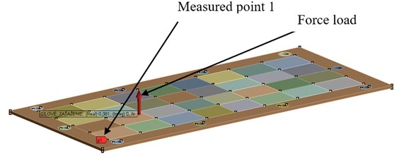
The harmonic (response) analysis is used to determine steady-state response of the linear structure to loads that vary harmonically with time. There are some differences compared with modal analysis. The applied loads and supports in the final element model are very important. In order to verify experimental measurement mentioned above, the free support and force load is applied to the numerical simulation. In the mathematical model the modal damping is also considered from the experimental modal analysis. An entire numerical model composed of the load and the measuring points is shown in Fig. 1.
Fig. 1The numerical model of the harmonic response analysis
3. Results
The main goal of the experimental modal analysis is to obtain the eigen frequencies, eigen shapes and mode damping in the examined bandwidth. From the experimental measurement of the plates, the FRFs are primarily investigated. From the peaks of these 44 FRFs, the modal parameters are evaluated. An example of the first five structural modes are shown in Table 2. In Table 2. is also evaluated the comparison of chosen eigen modes of the thin flat plate. According the previous mentioned methods, the analytical results are compared with the experimental measurement. It can be seen in Table 1, that considerably bigger differences occurred using analytical technique.
Table 1Eigen frequencies [Hz] of the 3 mm plate
Mode | Experiment | Analytical calculation | Difference [%] |
1 | 126 | 126 | 0 |
2 | 172 | 177 | 2,9 |
3 | 348 | 335 | -3,7 |
4 | 373 | 389 | 4,3 |
5 | 634 | 589 | -7,1 |
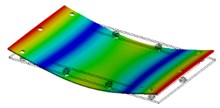
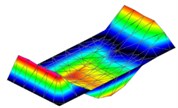
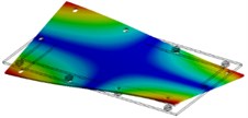
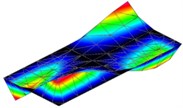
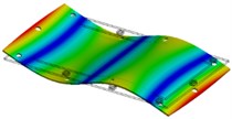
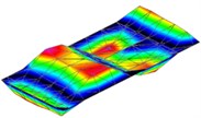
As was mentioned above the modal damping is obtained from experimental measurement. This third parameter is undoubtedly the most important from the whole of those three modal parameters. Modal damping is one of main input parameters of the numeric simulation in terms of harmonic response analysis. It is significant to clarify that each mode of the structure has got a specific value of modal damping. On the Fig. 2. can be seen that there are some differences in amplitudes between experimental data and simulation. In the picture the bending mode is shown, the max (red area) and min (blue area) amplitudes of normal velocities are coloured. A black area on the picture is place where the structure was excited. Labels on Fig. 2.: E – Experiment, S – Simulation.
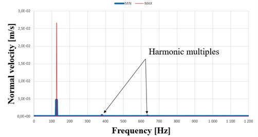
By the harmonic response analysis, the real amplitudes in terms of frequencies are examined and verified. In amplitude-frequency graph (in Fig. 3. the maximum and minimum amplitudes at point n.1 is checked and investigated. In such a thin, light-damped structures the results from experiment and simulation could be inaccurate oftentimes. It is mostly caused by damping estimation during post-processing.
Table 2Modal parameters of the flat 3 mm plate
Mode | Simulation | Experiment | Difference [%] |
1 | 126 Hz | 126 Hz | 0 |
 |  | ||
2 | 172 Hz | 172 Hz | 0 |
 |  | ||
3 | 350 Hz | 348 Hz | 0,6 |
 |  | ||
4 | 373 Hz | 373 Hz | 0 |
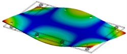 | 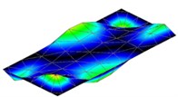 | ||
5 | 627 Hz | 634 Hz | –1,1 |
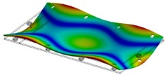 | 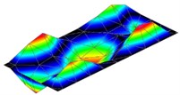 |
Fig. 2Amplitude comparison of the normal velocities of the first structural mode
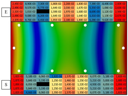
Fig. 3Amplitude – frequency graph at point n.1 of the plate
4. Conclusions
An investigation presented in this paper is a specific case of the vibration analysis in thin flat structures. The planar plates are generally simple structures, what could tend to easy way of determination of modal parameters. It is not always true. From the perspective of the eigen frequencies and the shapes, the obtained results from the experiment and simulation are relatively very accurate. But the damping estimation of these lightly-damped structures, it has got a lot of difficulties. Mainly when the whole experimental model is influenced by several factors: support configuration, vibration exciter and his components, the contact/contactless response sensors and so on. The modal damping estimation also depends on the algorithm (Polyreference frequency, Polyreference time, Rational fraction polynomial , etc.) used in post-processing software. The modal damping is generally known as the most complicated modal parameter to determine.
However, this paper describes a brief preview of the modal analysis application on the simple structure. The article shortly explains importance of the used approaches.
References
-
Rehak K., Kopeckova B., Prokop A. Numerical simulation of gearbox structure dynamics focused on backlash influence. Vibroengineering Procedia, Vol. 13, 2017, p. 115-120.
-
Ewins D. J. Modal Testing: Theory and Practice. Letchworth. Research Studies Press, England, 1984.
-
Leissa Arthur W. Vibration of Plates. NASA, Washington, D. C., 1969.
-
Frankovský Peter. Using Modal Analysis for Vibrating Diagnosis Machinery. Technical University of Kosice, Faculty of Mechanical Engineering, 2011.
-
Blevins Robert D. Formulas for Natural Frequency and Mode Shape. Krieger Publishing Company, USA, 2001.
Cited by
About this article

The research leading to these results has received funding from the Project FSI-S-17-4104 granted by specific university research of Brno University of Technology. The authors gratefully acknowledge this support.
