Abstract
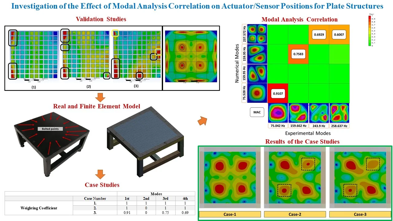
In this study, a mode combination approach is proposed to place actuator/sensor pairs according to the experimental modal analysis results. The method is carried out by combining modes using the weighting coefficients with a finite element package program. First, this approach is applied to four different structures presented in the previous works in literature to compare and verify. Our results demonstrate that the determined best locations overlap well with the published results. Then, this combination approach is applied to the steel plate with bolt connections on four sides to determine actuator/sensor (a/s) pairs’ placement accuracy, which is directly related to experimental/numerical modal correlation. For this purpose, three different cases varying by weighting coefficients are determined to show the modal correlation's effectiveness. Finally, the possible best a/s positions for three cases are compared. In conclusion, the presented mode combination approach is a fast and practical solution for determining a/s pairs’ placement, and the experimental/numerical modal analysis correlation directly affects the placement's success.
Highlights
- Actuator/Sensor Placement
- Modal Correlation
- Active Vibration Control
1. Introduction
Many studies have been performed on active vibration control. All these studies are basically based on two essential topics: modeling and controller design. The importance and necessity of active methods are emphasized in many studies, where passive methods are not sufficiently effective in structural vibration control. To that end, researchers have successfully tried many active methods of vibration control [1-5]. Researchers have created smart structures with the help of piezoelectric-material-based sensors and actuators and concluded their targeted studies with different control algorithms [6-8]. Besides, the optimal placement of sensors and actuators has been a point of focus for researchers to increase the controller's performance. The theoretical and experimental results of modeling the smart plate for active vibration control are presented by Yaman, Caliskan [9], which used the ANSYS software to obtain the smart plate’s finite element model. The maximum permissible piezoelectric operating voltage is determined using this model to calculate the optimum sensor locations. The optimization of the piezoelectric actuator and sensor positions for active vibration control is emphasized by Bruant, et al. [9], where two adaptive optimization criteria are applied to ensure good observability or controllability structure to consider the residual modes to limit the infiltration effect. A new formulation of the optimal position/orientation of the piezoelectric actuators/sensors bonded to the rectangular plate for the active vibration control is proposed by Biglar, et al. [10], where a genetic algorithm method is used to calculate the optimal position/orientation of the piezoelectric actuators/sensors. An experimental and numerical active vibration control study is presented by Boz, et al. [11], where piezoelectric patches are bonded on a plate clamped by four edges. One of the piezoelectric actuators is used as a control actuator, and the other is used as a disturbance actuation. They present the model's controllability measurement to determine the optimal locations of the proposed structure. In similar research, the adaptive control matrix and the individual value decomposition approach are used to determine the optimal placement of 10 piezoelectric actuators on a thin plate [12], where the singular value decomposition is accepted as a fitness function, and the optimal positions of the actuators are obtained by maximizing with the improved heuristic genetic algorithm. As a result, optimizing the piezoelectric actuators’ position in active vibration control increased the damping capability. Theoretical and experimental active vibration control of a cylindrical shell using piezoelectric actuators is presented by Loghmani, et al. [13], where three piezoelectric disc actuators are bonded to the shell structure. One of them is a disturbance actuator, and the others are defined as sensor and control actuator. As a result of deformations observed in vibration modes, it is concluded that the actuator positions should be close to the middle of the cylinder. Bendine, et al. [14] presented a study about the active vibration control of a composite plate by using discrete piezoelectric patches. They have proposed the optimal position of piezoelectric patches by using an optimization based on LQR performance. A genetic algorithm is implemented to investigate the best configuration. Modeling and optimization studies are conducted for active vibration control. Hence, it can be said that researchers have conducted investigations from different perspectives and often defined actuator configurations in high-amplitude regions that occur in vibration modes [15, 16]. Another original and valuable work is presented in [17]. A practical method is proposed to obtain the optimal location of sensor/actuator (s/a) pairs for active vibration reduction of a flexible structure. It is suggested that when these optimal positions are excited in resonance modes, there would be locations where the sensors could produce the maximum output voltage. Small piezoelectric sensors bonded symmetric and asymmetric plates are modeled using the ANSYS in order to verify this new method.
In this study, a new application for the actuator/sensor pairs’ best placement is proposed. This method combines modes using the Design Assessment Toolbox (DAT) of ANSYS/Workbench based on modal analysis results. DAT provides the ability to perform a combination of solutions for static, modal, harmonic, random vibration, response spectrum, transient dynamic, or structural analysis [18]. Thus, it is the process of combining one or more existing analysis results with the coefficients that can be determined. This method can also be defined as a more computable, faster, and more powerful mechanical combination solution. For this reason, DAT is an effective solution to combine numerical analysis of the structures. This study's approach combines only the natural modes obtained from numerical modal analysis to calculate the optimal locations.
Firstly, the validation studies are presented to the success of the proposed new approach. For this purpose, the different methodology offered by the researchers in [11, 17] related to the optimal actuator/sensor placement is examined in detail. As mentioned earlier, four different models presented in these studies are used to apply the mode combination using the DAT. The optimal locations of models presented in these studies and the best locations obtained from the mode combination method are compared to verify our methodology. Our results are overlap well with the published results. After the verification, the proposed mode combination application is carried out on the real structure. The steel plate with bolt connections on four sides is investigated to determine a/s pairs’ best placement. The experimental modal analysis was conducted in our previous study and compared with the finite element analysis (FEA) according to the Modal Assurance Criterion (MAC). In order to indicate that experimental/numerical modal correlation is directly related to the placement accuracy, three different cases are investigated.
2. The validation of the mode combination application
In this section, the mode combination using the DAT is applied to four different structures presented in the literature’s works to compare and verify. For this aim, two different studies are handled in detail [11, 17] related to the optimal a/s placement. Four different models with several boundary conditions presented in these studies are used to compare our approach.
Firstly, Daraji and Hale [17] presented three different configurations that are handled. Our study uses these models by maintaining the dimensional, physical and mechanical properties to implement our approach. As is the reference study, one hundred pieces of the piezoelectric patch are bonded on the structure numerically. A finite model is obtained for coupled field analysis (for piezoelectric) according to the technique presented in [6]. The piezoelectric material properties are defined as provided in the reference study. The mode combination is applied to these models using the DAT after the numerical modal analysis in ANSYS. The six modes of the structures are combined using unit weighting coefficients by DAT in order to obtain the optimal location. After this, the equivalent strain responses are examined of these three structures. Accordingly, Fig. 1(a) depicts the possible optimal a/s positions of the three different plates with the proposed locations by [17].
Fig. 1a) Best positions obtained as a result of the mode combination; 1 – cantilevered plate model; 2 – one corner fixed cantilevered plate model; 3 – T-shape supported cantilevered plate model (red color: obtained optimal positions in this study, black frames: proposed optimal positions by Daraji et al., [17], yellow frames: suggested optimal locations), b) best positions of the steel plate clamped by four edges (red color: obtained optimal positions in this study, black frames: proposed optimal positions by Boz et al., [11]
![a) Best positions obtained as a result of the mode combination; 1 – cantilevered plate model; 2 – one corner fixed cantilevered plate model; 3 – T-shape supported cantilevered plate model (red color: obtained optimal positions in this study, black frames: proposed optimal positions by Daraji et al., [17], yellow frames: suggested optimal locations), b) best positions of the steel plate clamped by four edges (red color: obtained optimal positions in this study, black frames: proposed optimal positions by Boz et al., [11]](https://static-01.extrica.com/articles/22412/22412-img1.jpg)
a)
![a) Best positions obtained as a result of the mode combination; 1 – cantilevered plate model; 2 – one corner fixed cantilevered plate model; 3 – T-shape supported cantilevered plate model (red color: obtained optimal positions in this study, black frames: proposed optimal positions by Daraji et al., [17], yellow frames: suggested optimal locations), b) best positions of the steel plate clamped by four edges (red color: obtained optimal positions in this study, black frames: proposed optimal positions by Boz et al., [11]](https://static-01.extrica.com/articles/22412/22412-img2.jpg)
b)
Second, Boz et al. [11] presented a numerical and experimental active vibration control study, where two piezoelectric patches are bonded on a steel plate clamped by four edges. One of the piezoelectric actuators is used as a control actuator, and the other is a disturbance actuation. In our study, the proposed structure by [11] is modeled by maintaining the dimensional, physical, and mechanical properties to implement our approach. As is the reference study, modal parameters of the first four modes are obtained to apply mode combination using unit weighting coefficients in DAT after the numerical modal analysis in ANSYS. Similarly, the equivalent strain response of the structure is investigated after the mod combination operation. Accordingly, Fig. 1(b) depicts the possible optimal a/s positions of the steel plate clamped by four edges with the proposed locations by [11].
3. Placement of actuator/sensors for plate structure with bolt connections
In this section, our approach called mode combination is applied to the steel plate with bolt connections on four sides to calculate the best a/s locations on the structure. The plate structure and the finite element model are shown in Fig. 2.
Fig. 2The steel plate with bolt connections on four sides a): actual model b) finite element model
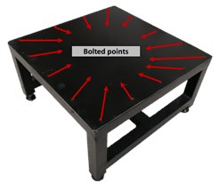
a)
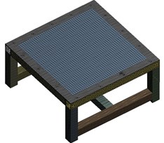
b)
As summarized in Table 1, three cases are investigated in the steel plate to show the experimental/numerical modal analysis correlation effectiveness. Here, Case-1 is considered only by combining the structure's numerical modes with the unit weighting coefficients. In Case-2, only the highly correlated modes are combined with the unit weighting coefficients by using experimental/numerical modal analysis results. Finally, in Case-3, highly correlated modes are combined with the weighting coefficients obtained from MAC values.
Table 1Cases methodology for the investigation
Cases | Mode Combination type | Weighting coefficient |
Case-1 | Only numerical modes | The weighting coefficient is selected as unity for each mode |
Case-2 | Highly correlated modes | The weighting coefficient is selected as unity for each mode |
Case-3 | Highly correlated modes | The weighting coefficient is selected according to the MAC values for each mode |
In order to investigate the cases in this study, the experimental modal parameters of the steel plate with bolt connections on four sides were determined in our previous study [19, 20]. Also, the numerical modal analysis result was compared with the experimental results. LMS/VirtualLab software was used to compare the modal parameters as a result of the testing and finite element analysis (FEA). The Modal Assurance Criterion (MAC) values of the test and finite element model were calculated and shown in Fig. 3(b) with the mode shapes and natural frequencies as presented in our previous study [19, 20]. Our approach that mode combination method by using DAT is applied to the models of the cases as presented in Table 2 using different weighting coefficients.
Table 2Weighting coefficients of all cases for the mode combination
Weighting coefficient | Case number | Modes | |||
1st | 2nd | 3rd | 4th | ||
1 | 1 | 1 | 1 | 1 | |
2 | 1 | 0 | 1 | 1 | |
3 | 0.91 | 0 | 0.75 | 0.69 | |
Fig. 3a) The equivalent strain responses of the cases, b) numerical and experimental modal analysis correlation [19, 20]
![a) The equivalent strain responses of the cases, b) numerical and experimental modal analysis correlation [19, 20]](https://static-01.extrica.com/articles/22412/22412-img5.jpg)
a)
![a) The equivalent strain responses of the cases, b) numerical and experimental modal analysis correlation [19, 20]](https://static-01.extrica.com/articles/22412/22412-img6.jpg)
b)
The mode combination method is applied by using the DAT of the Ansys/Workbench based on the modal analysis results for the presented cases. After performing the mode combination, the equivalent strain response is investigated to calculate the best a/s positions. Fig. 3(a) depicts the equivalent strain response of all cases. It is concluded that the red zones where the equivalent strain is the maximum are the best regions for multi-modal vibration control. In Case-1, when the first four modes are combined, higher strain zones have occurred in four locations. Therefore, the actuators/sensors can be placed on these zones to control the structure's first four modes of vibrations, thus realizing high-performance vibration control. When Case-2 and Case-3 are examined, a lower level of strain occurred in the regions marked in black due to the combination of three modes. These lower strain zones will provide lower control performance than other high zones considered the best placement.
4. Results and discussions
This study conducted an approach for the best placement of the actuator/sensor pairs using the mode combination method based on the superposition theorem’s principle. In order to verify the method, applications of the studies were investigated in the literature. First, a study containing three different configurations has been proposed by Daraji et al. [17]. The optimal location results have been compared with the reference study to verify this study’s mode combination method, as depicted in Fig. 1(a). The results are observed to be overlapped when the verification is tested. Only the second and third plates' results are verified at the rate of 83.3 % when the six piezoelectric actuators are used. Only two positions are incompatible for these plates, as shown in Fig. 1(a), that can be attributed to the numeric values in the reference study. Besides, as a result of the mode combination method, two additional positions for the third plate are marked in Fig. 1(a) in yellow. According to equivalent strain, these locations, which are the highly concentrated regions, are presented in addition to the reference study. Second, a numerical and experimental active vibration control study was presented by Boz, et al. [11], where two piezoelectric patches are bonded on a steel plate clamped by four edges. The reference work is tested for verification; the results overlap, as depicted in Fig. 1(b). A success rate of 100 % is achieved by the mode combination method to verify the optimal positions.
Then, three cases (Case-1, Case-2, and Case-3) are examined to emphasize the importance of experimental modal analysis in best a/s placement based on numerical modal analysis. Fig. 3(a) is examined; it is observed how the best regions will change by combining the correct modes. The symmetric modes occur in the numerical analysis of symmetrical structures, especially plate-like, due to their nature. However, this is not the case in actual systems. Therefore, the verification of numerical analysis with experimental studies increases the value of the engineering problems’ solutions. In the studies presented in the literature, the optimal region determination studies proven with numerical applications should be supported experimentally. Otherwise, a different result may be obtained, as given in Fig. 3(a).
As a result, the presented method shows a fast and practical solution to the actuator and sensor for multimode vibration control. Further, the superiority of this method can be explained as follows.
1) Any optimization technique or formulation of the combining is not required. Equivalent strain regions are obtained by combining modal modes with the coefficients using the Design Assessment Toolbox. 2)The structural and dynamic analysis results such as random-vibration, harmonic-response can be combined with the modal analysis data results or each other. In this way, more realistic and more effective placement can be obtained. 3) It can be fastly adapted to changes (geometry, material, boundary condition, etc.).
5. Conclusions
This paper presents an efficient application to calculate the actuator/sensor pairs’ best locations, achieving higher performance active vibration control. The mode combination method is implemented to the four different structures to compare with the previous literature’s works. In conclusion, the mode combination method by using Ansys/Design Assessment Toolbox is an effective tool in numerical environments with all these compared results. Moreover, the experimental modal analysis correlation directly affects the placement in this approach. Therefore, the experimental verification should be realized, especially in symmetrical structures where symmetrical modes can be occurred. Even, it can be performed better by determining the location with model updates application in the complex models.
References
-
E. Gülbahçe and M. Çelik, “Active vibration control of a smart beam by a tuner-based PID controller,” Journal of Low Frequency Noise, Vibration and Active Control, Vol. 37, No. 4, pp. 1125–1133, Dec. 2018, https://doi.org/10.1177/1461348418782169
-
G. Tairidis, G. Foutsitzi, P. Koutsianitis, and G. E. Stavroulakis, “Fine tuning of a fuzzy controller for vibration suppression of smart plates using genetic algorithms,” Advances in Engineering Software, Vol. 101, pp. 123–135, Nov. 2016, https://doi.org/10.1016/j.advengsoft.2016.01.019
-
E. Wang, J. Zhang, and L. He, “Active vibration control of piezoelectric intelligent structures,” Journal of Computers, Vol. 5, No. 3, Mar. 2010, https://doi.org/10.4304/jcp.5.3.401-409
-
E. Omidi and N. Mahmoodi, “Hybrid positive feedback control for active vibration attenuation of flexible structures,” IEEE/ASME Transactions on Mechatronics, Vol. 20, No. 4, pp. 1790–1797, Aug. 2015, https://doi.org/10.1109/tmech.2014.2354599
-
Sm Khot and Nitesh P. Yelve, “Modeling and response analysis of dynamic systems by using ANSYS© and MATLAB©,” Journal of Vibration and Control, Vol. 17, No. 6, pp. 953–958, 2011.
-
F. Lüleci, “Active vibration control of beam and plates by using piezoelectric patch actuators,” Master Thesis, Middle East Technical University, Ocak, 2013.
-
E. Omidi and S. N. Mahmoodi, “Consensus positive position feedback control for vibration attenuation of smart structures,” Smart Materials and Structures, Vol. 24, No. 4, p. 045016, Apr. 2015, https://doi.org/10.1088/0964-1726/24/4/045016
-
N. D. Zorić, A. M. Simonović, Z. S. Mitrović, S. N. Stupar, A. M. Obradović, and N. S. Lukić, “Free vibration control of smart composite beams using particle swarm optimized self-tuning fuzzy logic controller,” Journal of Sound and Vibration, Vol. 333, No. 21, pp. 5244–5268, Oct. 2014, https://doi.org/10.1016/j.jsv.2014.06.001
-
I. Bruant, L. Gallimard, and S. Nikoukar, “Optimal piezoelectric actuator and sensor location for active vibration control, using genetic algorithm,” Journal of Sound and Vibration, Vol. 329, No. 10, pp. 1615–1635, May 2010, https://doi.org/10.1016/j.jsv.2009.12.001
-
M. Biglar, M. Gromada, F. Stachowicz, and T. Trzepieciński, “Optimal configuration of piezoelectric sensors and actuators for active vibration control of a plate using a genetic algorithm,” Acta Mechanica, Vol. 226, No. 10, pp. 3451–3462, Oct. 2015, https://doi.org/10.1007/s00707-015-1388-1
-
U. Boz, U. Aridogan, and I. Basdogan, “A numerical and experimental study of optimal velocity feedback control for vibration suppression of a plate-like structure,” Journal of Low Frequency Noise, Vibration and Active Control, Vol. 34, No. 3, pp. 343–359, Jun. 2015, https://doi.org/10.1260/0263-0923.34.3.343
-
D. Chhabra, G. Bhushan, and P. Chandna, “Optimal placement of piezoelectric actuators on plate structures for active vibration control via modified control matrix and singular value decomposition approach using modified heuristic genetic algorithm,” Mechanics of Advanced Materials and Structures, Vol. 23, No. 3, pp. 272–280, Mar. 2016, https://doi.org/10.1080/15376494.2014.949932
-
Mohammad Danesh, “Theoretical and experimental study of active vibration control of a cylindrical shell using piezoelectric disks,” Journal of Low Frequency Noise, Vibration and Active Control, Vol. 34, No. 3, pp. 269–287, Jan. 2015.
-
K. Bendine, F. B. Boukhoulda, B. Haddag, and M. Nouari, “Active vibration control of composite plate with optimal placement of piezoelectric patches,” Mechanics of Advanced Materials and Structures, Vol. 26, No. 4, pp. 341–349, Feb. 2019, https://doi.org/10.1080/15376494.2017.1387324
-
M. F. Labanie, J. S. Mohamed Ali, and M. S. I. S. Dawood, “Optimal location of piezoelectric patches for active vibration control,” IOP Conference Series: Materials Science and Engineering, Vol. 184, No. 1, p. 012012, Mar. 2017, https://doi.org/10.1088/1757-899x/184/1/012012
-
L. Sun, W. Li, Y. Wu, and Q. Lan, “Active vibration control of a conical shell using piezoelectric ceramics,” Journal of Low Frequency Noise, Vibration and Active Control, Vol. 36, No. 4, pp. 366–375, Dec. 2017, https://doi.org/10.1177/1461348417744304
-
A. H. Daraji, J. M. Hale, and J. Ye, “New methodology for optimal placement of piezoelectric sensor/actuator pairs for active vibration control of flexible structures,” Journal of Vibration and Acoustics, Vol. 140, No. 1, p. 01101, Feb. 2018, https://doi.org/10.1115/1.4037510
-
A. W. Ansys, “14.0 help documentation [db],” in Mechanical APDL ANSYS Parametric Design Language Guide, ANSYS, 2011.
-
E. Gülbahçe and M. Çelik, “Experimental modal analysis for the plate structures with roving inertial shaker method approach,” Journal of Low Frequency Noise, Vibration and Active Control, p. 146134842110393, Sep. 2021, https://doi.org/10.1177/14613484211039323
-
E. Gülbahçe, “Helikopter gövdesi kabuk yapılarının deneysel analiz yöntemleriyle aktif titreşim kontrolü,” Konya Teknik Üniversitesi, YÖK Tez No: 688239, 2021.
About this article

This study is carried out within the scope of the smart structure project supported by TUBA (Academy of Sciences of Turkey).
