Abstract
This paper presents the design and implementation of a robust model reference controller (RMRC) for active vibration suppression of a flexible structure, a cantilevered beam. The flexible beam is an aluminum beam in the cantilever configuration and is equipped with surface-bonded PZT (lead zirconate titanate) sensors/actuators. PZT is a piezoelectric material with a strong piezoelectric effect, and is a commonly used smart material. Since the fundamental vibration mode of the beam is the major concern in this paper, a linear model which represents the dominant vibration mode is developed and used as the plant model for the control design. Based on this linear model, a robust model reference controller (RMRC) is developed to suppress the beam’s vibration. Vibration suppression simulations and experiments are conducted. Both results show that the proposed controller achieves effective vibration suppression of the flexible beam using PZT sensors and actuators.
1. Introduction
In the past decades, there has been an increasing interest in the application of smart material and structure technology in the active vibration control of flexible structures [1-18]. Smart materials, such as piezoceramic materials, optical fibers and shape memory alloys, integrated with flexible structures, function as sensors or actuators for vibration controls. Piezoceramic materials have unique characteristics, such as solid state actuation, wide bandwidth, light weight and long fatigue life. They can be used as both sensors and actuators. A commonly used piezoceramic material is the PZT (lead zirconate titanate), which has a strong piezoelectric effect. Piezoceramic materials have been widely used in many vibration suppression applications with a number of control methods, such as LQG (Linear Quadratic Gaussian), [1] strain rate feedback control [2], negative velocity feedback control [4], -synthesis control [19], pole placement control [20, 21], adaptive control [22], and sliding-mode based robust control [23].
Model reference control (MRC) [24, 25], often used in conjunction with adaptive methodology, has the capacity to control an unknown plant to follow a prescribed trajectory. MRC has been applied to various systems, such as electrical actuators [26], single flexible robot [27], etc. Since vibration control problems usually involve trajectory tracking, MRC has also been applied to vibration control [9-11]. There are only a few reports on vibration suppression using model reference control and piezoceramic actuators. A finite dimensional discrete-time MRC algorithm was used to suppress the vibrations in a flexible beam with a piezoelectric sensor and actuator [12]. In [13], a fuzzy model reference control was used for vibration control of a smart flexible beam. Using piezoelectric damping-modal actuators/sensors, Li and Nien studied the modeling and active vibration control of a laminated smart beam [14]. Based on Hamilton’s principle, Hong et al. derived the equation of motion for a smart beam and designed an active vibration suppression system using a multi-objective state-feedback controller [15]. Li and Yang investigated the dynamic response and active control of a composite cylindrical shell with piezoelectric shear actuators [16]. Ray and Pradhan studied the performance of piezoelectric composites for active damping of laminated composite shells [17]. Ray and Shivakumar also investigated active constrained layer damping of geometrically nonlinear transient vibration of composite plates using piezoelectric fiber-reinforced composite [18].
In this paper, a robust model reference control is proposed for vibration suppression of a flexible beam with a surface bonded PZT sensor and actuator. First, an experimental setup is constructed. In the setup, a cantilevered flexible aluminum beam with two PZT actuators and one PZT sensor is used for enabling the feedback control. Then, the analysis of the beam’s vibration is conducted. The analysis results in a linear second-order single-degree-of-freedom (SDOF) model for the beam’s dominant modal vibration. With regard to this model, the design of a robust model reference controller is carried out. The control law is motivated from Lyapunov’s second method. Finally, the proposed controller’s ability to suppress vibration is evaluated by numerical simulations and validated by experiments.
2. The experimental setup
As shown in Fig. 1, a “smart” flexible structure – a cantilevered beam integrated with the PZT sensor/actuator-is developed for testing the proposed controller. The beam is a 736.5 mm long, 53.1 mm wide and 1 mm thick aluminum strip (see Table 1 for other specifications of the beam). At its root, two identical PZT patches are bonded on the opposite lateral surfaces of the beam. They are used as actuators to generate a bending force for active control of the beam. Another smaller PZT sensor is bonded at the location adjacent to one PZT actuator so that the PZT sensor and actuator can be regarded as in the collocated configuration. The specifications of the PZT patches are listed in Table 2.
Fig. 1The flexible beam experimental setup
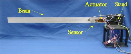
Fig. 2A schematic of the experimental setup
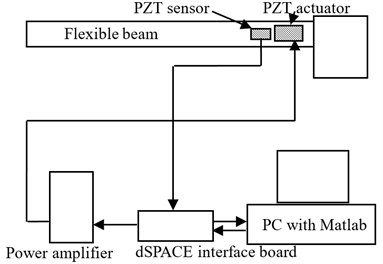
As illustrated in Fig. 2, the experimental setup used in this paper is comprised of a real-time data acquisition system – dSPACE, a PC with the Matlab/Simulink software, a power amplifier and the flexible beam. The controller is implemented in the platform of the Matlab/Simulink software. The control command is amplified by the power amplifier before it is applied on the PZT actuators. When subjected to vibration excitations, the PZT sensor has a voltage output, which is directly proportional to the strain at the location of the sensor near the root of the beam. It is well known that a cantilevered beam’s vibration can be represented by the strain near its root. Therefore, in this research, we directly use the PZT sensor output to represent the vibration status of the cantilevered beam.
Table 1Beam properties
Quality | Description | Units | Value |
Beam length | mm | 736.5 | |
Beam width | mm | 53.1 | |
Beam thickness | mm | 1 | |
Beam density | kg/m3 | 2690 | |
Modulus of elasticity | N/m2 | 7.03×10¹⁰ |
Table 2Properties of PZT patches used on the beam
Quality | Description | Units | PZT Actuator | PZT Sensor |
Dimensions | mm | 46×33.27×0.25 | 14×7×0.25 | |
Strain coefficient | C/N | 7.41×10⁻¹⁰ | 7.41×10⁻¹⁰ | |
Strain coefficient | C/N | –2.74×10⁻¹⁰ | –2.74×10⁻¹⁰ | |
PZT density | kg/m3 | 7500 | 7500 | |
Young’s modulus | N/m2 | 6.3×10¹⁰ | 6.3×10¹⁰ |
Fig. 3The sensor’s output in the case of free vibration
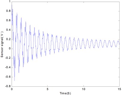
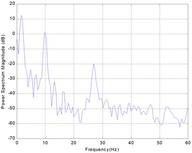
Fig. 4The PSD plot of the free vibration of the beam
3. The model of the beam
The MRC Design is model-oriented. A beam model which is capable of taking the effect of the PZT actuators into account must be developed in advance for MRC design. It is well known that a flexible beam’s vibration is complicated and has infinite vibration modes. However, only a few modes are dominant and critically affect the characteristics of vibration. Therefore, the scope of the proposed vibration controller is confined to the most critical vibration mode of the flexible beam. To obtain the mathematic model of the dominant vibration mode of the PZT actuated flexible beam, a modal analysis technique is adopted to uncouple a differential equation which represents vibration of the flexible beam, and then open-loop testing is conducted to determine which mode is dominant.
First, we study the forced motion of the cantilevered flexible beam driven by the PZT actuators. The motion of the flexible beam with the PZT actuators is governed by the following partial differential equation [28]:
where is the beam deflection; is the distance along the beam; and are the material’s Young’s modulus and moment of inertia; is the beam’s cross-section area; is the beam material density; and is the two PZT actuator’s bending force acting at the point . is an overall damping ratio.
Applying the modal analysis method, we can express the beam deflection in the form:
where are the eigenfunctions and are the dimensionless modal coordinates. Substituting Eq. (2) into Eq. (1), we obtain the beam modes in the dimensionless modal coordinates as:
where is the natural frequency of the th vibration mode and is the modal damping ratio. Eq. (3) is a second-order nohomogenous equation for each vibration mode, independently. The effect of the bending force depends on only each vibration mode. Thus, a model of any vibration mode can be directly derived from Eq. (3).
In the second step, an open-loop test is carried out on the beam to investigate the vibration intensity of each mode. In testing, the beam is excited by sending a sweep sine signal to the PZT actuators for five seconds. The frequency of the sweep sine signal starts at 0.5 Hz and ends at 200 Hz in order to excite several modes of the beam. After excitation, the beam freely oscillates until all energy is damped out.
The beam’s free vibration is shown in Fig. 3. The vibration required more than 15 seconds to cease. Fig. 4 shows a power spectrum density (PSD) plot of the free vibration of the beam. It is seen that the first PSD peak value occurs at 1.63 Hz. Accordingly, the frequency of the first mode is 1.63 Hz. It is evident that the PSD value of the first mode is the greater than all others. Therefore, the first mode is dominant and only the first mode is selectively considered in the vibration control.
Thus, let 1 in Eq. (3) and replace the variable with , then the first mode of vibration is given as:
where and are the natural frequency and damping ratio of the first mode, respectively. a constant coefficient, is equal to .
The control force , provided by the PZT actuators, is a function of the applied electrical field (voltage ) across the PZT patches. Generally, the relationship of the force and applied voltage is hysteretic. However, in this paper, the hysteretic effect is negligible. A linear model links the applied electrical voltage to the force as in the form:
Denoting , , the state space representation of Eq. (4) is:
By defining matrices:
Eq. (4) is rewritten as:
4. Model reference control design
4.1. Reference model
The first step for MRC design is choosing an appropriate reference model. The reference model should represent the desired performances with regard to the control goals: to increase damping. Theoretically, any overdamped second-order system or first-order system which satisfies our vibration suppression requirement is a candidate of the reference model. As discussed earlier, the beam’s dominant first vibration mode is represented by a second-order system. Therefore, in this paper, a second-order system that has the same natural frequency as the flexible beam, but with a larger damping ratio, is used as the reference model, as shown in Eq. (8):
where the subscript represents the reference model. is the reference input to the reference model. Normally, is much larger than that of the original plant.
The state space of the reference model Eq. (8) can be expressed as:
where:
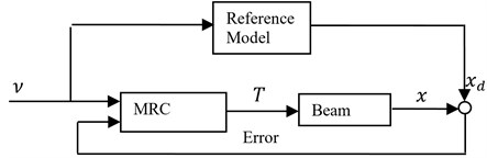
Fig. 5The block diagram of a model reference control system
4.2. Control design
Fig. 5 illustrates the configuration of the closed-loop system with a model reference controller. The errors, differences between the states of the beam and those of the reference model, are returned as feedback to the MRC. We intend to design an MRC to guarantee the asymptotic stability of the closed-loop system, i.e. the errors go to zero as .
Define the error vector, . Based on Lyapunov’s second method, the error is globally asymptotically stable if there exists a Lyapunov function whose derivative is globally negative definite.
In the initial step, choose a Lyapunov function candidate:
where is a positive definite matrix and a solution of the Lyapunov Eq. (11):
here, .
The derivative of the above Lyapunov function candidate is given in Eq. (12):
where .
Expanding the second term of Eq. (12) gives:
The applied control voltage is chosen such that the above expression is negative. Hence, could be determined as shown in Eq. (14):
Substituting Eq. (14) into Eq. (13), we get:
Substituting Eqs. (15) and (11) into Eq. (12), the derivative of the Lyapunov function candidate is rewritten as:
It is obvious that Eq. (16) is equal to zero if and only if 0 and 0, otherwise it is negative; thus is globally negative definite. Therefore, the closed loop system with the proposed controller is asymptotically stable.
However, the beam’s model has its uncertainties, such as the parameter variation, nonlinearity and disturbance. With consideration of the uncertainties, the beam’s vibration at its first mode is modeled as:
where the unknown function vector represents the uncertainties in modeling. After replacing the old beam’s state equation with Eq. (17), then Eqs. (12) and (13) are respectively rewritten as:
We assume that all uncertainties are bounded. Hence:
where the positive constant is the boundary of the scalar function . Thus, the control action is given as:
Substituting Eq. (21) into (19):
hence, Eq. (18) becomes:
It is evident that is globally negative and definite so that the closed loop system is asymptotically stable.
The control law expressed in (21) features the robustness of the uncertainties in modeling. It is capable of dealing with parameter variations, nonlinearities and external disturbances. However, this robust MRC involves a sign function component which commonly induces a chattering problem. In practice, to avoid chattering, a dead zone is used to reduce the switching frequency.
Because only the first vibration mode is selectively concerned in the vibration control, the truncated higher modes, which are possibly excited by the high frequency component of the control signal, must be cut off. Therefore, a low-pass filter is employed to filter the control signal.
5. Numerical simulations
Before implementing of the proposed controller, simulations of the beam’s responses to three different excitation signals are conducted. The simulations are programmed with Matlab/Simulink.
In the first case, two simulations are conducted: one is with control and the other is without control. In both simulations, the beam is excited by a sinusoidal signal with the same frequency as the first mode of the beam for a period of 5 seconds. Fig. 6 shows the beam’s response and the output of the reference model for the case without control, while Fig. 7 shows the same signals for the case with control. From Fig. 7, it is evident that the beam’s response follows the reference model’s output and it needs only 1 second for vibration to stop.
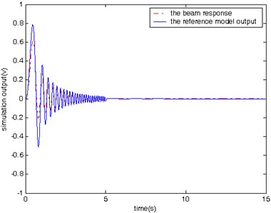
In the second case, simulations are conducted to compare the vibration with and without control in response to a sweep sine input lasting for a period of 5 seconds. The input signal changes its frequency from 0.5 Hz to 10 Hz. The beam’s response and the output of the reference model in the case with and without control are shown in Figs. 8 and 9, respectively. It is found that it takes 2 seconds for the controlled beam to stop vibration after excitation.
Please note that both Figs. 6 and 8 are for the cases without model reference control, and therefore there are large difference between the beam response and the reference model output. Since there no control action associated with Figs. 6 and 8, we expect the large difference. Figs. 6 and 8 are used mainly for comparison purpose with Figs. 7 and 9. Both Figures 7 and 9 are for the cases with model reference control. It is clear that the difference between the beam response and the reference model output is much smaller in Figs. 7 and 9 than that in Figs. 6 and 8, which demonstrates the effectiveness of the proposed model reference control for vibration suppression.
In the last case, the beam is subject to a unit impulse excitation. As shown in Fig. 10, the controlled beam behaves like an overdamped system.
Fig. 6The beam response and the reference model output without control (sine input)
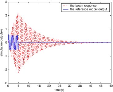
Fig. 7The beam response and the reference model output with control (sine input)
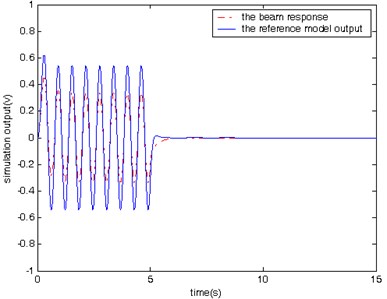
Fig. 8The beam response and the reference model output without control (sweep sine input)
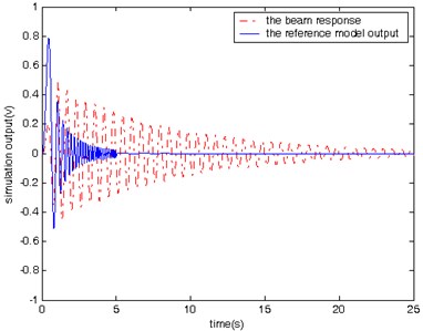
Fig. 9The beam response and the reference model output with control (sine input)
The simulation results obtained from testing of the controlled beam in responses to the three different excitation signals (Figs. 7, 9, and 10) demonstrate that proposed controller is capable of manipulating the beam to follow the reference model’s behavior from the vibration suppression perspective.
6. Experimental results
Using the aforementioned experimental setup, a vibration suppression experiment is conducted to verify the controller performance in an open environment. It is important to point out that two low-pass filters are placed in both the feedback loop and output channel to prevent the residual vibration modes of the beam from being excited.
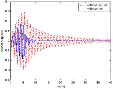
In the experiment, a sine wave signal with white noise is sent to the PZT actuators to excite the beam for 5 seconds. The responses of the beam in the cases with and without control are shown in Fig. 11. It shows that the vibration of the beam with control stops much more quickly than that in the case without control.
Fig. 10The beam response and the reference model output with control (impulse input)
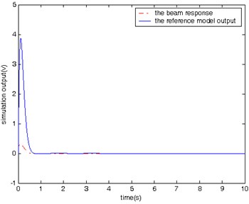
Fig. 11History of the beam’s vibration with and without control
7. Conclusions
In this paper, we presented our effort to control vibration of a flexible beam using a robust model reference controller and PZT actuator/sensor. The beam model was first presented, and then the modal analysis method was used to deduce the ordinary differential equation for each vibration mode. The dominant vibration mode was selectively considered for the vibration control based on the results of the open-loop testing of the beam. Lyapunov’s Indirect method was used in the design of the reference model controller. The proposed model reference controller featured its variable structure and robustness to the modeling uncertainties and external disturbances. To verify the vibration suppression performance of the proposed controller, simulations and experiments were conducted. The simulations were conducted in three different cases with three different inputs, respectively. For each input type, the vibration suppression was compared between the simulations with control and without control. Finally, the proposed controller was implemented in the experimental setup and experiments were conducted to test the controller. The results obtained from the simulations and experiments demonstrated the feasibility and effectiveness of the proposed model reference control for vibration suppression of the flexible beam. The future work will involve comparing the results of model reference control with those of other types of robust control methods.
References
-
Takahashi K., Bansaku K., Sands T., Matsuzaki Y. Sound and vibration control tests of composite panel using piezoelectric sensors and actuators. Proceedings of SPIE, Vol. 4327, 2001, p. 680-687.
-
Song G., Kotejoshyer B. Vibration reduction of flexible structures during slew operations. International Journal of Acoustics and Vibration, Vol. 7, Issue 2, 2002, p. 105-109.
-
Alkhatib R., Golnaraghi M. F. Active structural vibration control: a review. Shock and Vibration Digest, Vol. 35, Issue 5, 2003, p. 367-383.
-
Belyaev A. K., Indeitsev D. A. Proceedings of the 4th European Conference on Structural Control, St. Petersburg, Russia, 2008.
-
Fujino Y., Nishitani A., Mita A. Proceedings of the 5th World Conference on Structural Control and Monitoring, Tokyo, Japan, 2010.
-
Casciati S., Chen Z. A multi-channel wireless connection system for structural health monitoring applications. Structural Control and Health Monitoring, Vol. 18, Issue 5, 2011, p. 588-600.
-
Li Feng-Ming, Song Zhi-Guang, Chen Zhao-Bo Active vibration control of conical shells using piezoelectric materials. Journal of Vibration and Control, Vol. 18, Issue 14, 2011, p. 2234-2256.
-
di Bernardo Mario, Montanaro Umberto, Olm Josep M., Santini Stefania Model reference adaptive control of discrete-time piecewise linear systems. International Journal of Robust and Nonlinear Control, Vol. 23, 2013, p. 709-730.
-
Ko J., Strganac T. W., Junkins J. L., Akella M. R., Kurdila A. J. Structured model reference adaptive control for a wing section with structural nonlinearity. Journal of Vibration and Control, Vol. 8, Issue 5, 2002, p. 553-573.
-
Agarwala R., Ozcelik S., Faruqi M. Active vibration control of a multi-degree-of-freedom structure by the use of direct model reference adaptive control. Proceedings of the American Control Conference, Chicago, IL, Vol. 5, 2000, p. 3580-3584.
-
Gattulli V., Romeo F. Integrated procedure for identification and control of MDOF structures. Journal of Engineering Mechanics, Vol. 126, Issue 7, 2000, p. 730-737.
-
Gopinathan M., Pajunen G. A. Model reference control of vibrations in flexible smart structures. Proceedings of the IEEE Conference on Decision and Control, Vol. 4, 1995, p. 3551-3556.
-
Mayhan P., Washington G. Fuzzy model reference learning control: a new paradigm for smart structures. Smart Materials and Structures, Vol. 7, Issue 6, 1998, p. 874-884.
-
Lin J. C., Nien M. H. Adaptive control of a composite cantilever beam with piezoelectric damping- modal actuators/ sensors. Composite Structures, Vol. 70, 2005, p. 170-176.
-
Hong S., Park C. H., Park H. C. Vibration control of beams using multiobjective state-feedback control. Smart Materials and Structures, Vol. 15, 2006, p. 157-163.
-
Li H., Yang Y. Dynamic response and active control of a composite cylindrical shell with piezoelectric shear actuators. Smart Materials and Structures, Vol. 16, 2007, p. 909-918.
-
Ray M. C., Pradhan A. K. Performance of vertically and obliquely reinforced 1-3 piezoelectric composites for active damping of laminated composite shells. Journal of Sound and Vibration, Vol. 315, 2008, p. 816-835.
-
Ray M. C., Shivakumar J. Active constrained layer damping of geometrically nonlinear transient vibrations of composite plates using piezoelectric fiber-reinforced composite. Thin-Walled Structures, Vol. 47, 2009, p. 178-189.
-
Li Y. Y., Chen L., Li P. Modeling and vibration control of a plate coupled with piezoelectric material. Composite Structures, Vol. 62, 2003, p. 155-162.
-
Manning W. J., Plummer A. R., Levesley M. C. Vibration control of a flexible beam with integrated actuators and sensors. Smart Materials and Structures, Vol. 9, 2000, p. 932-939.
-
Bu X., Ye L., Su Z., Wang C. Active control of a flexible smart beam using a system identification technique based on ARMAX. Smart Materials and Structures, Vol. 12, 2003, p. 845-850.
-
Ma K. Vibration control of smart structures with bonded PZT patches: novel adaptive filtering algorithm and hybrid control scheme. Smart Materials and Structures, Vol. 12, 2003, p. 473-482.
-
Song G., Gu H. Sliding mode based active vibration control of a flexible beam using piezoceramic materials. Proceedings of the Tenth International Congress on Sound and Vibration (Stockholm, Sweden), July, 2003.
-
Slotine J. E., Li W. P. Applied Nonlinear Control. New Jersey, Prentice-Hall, Inc., 1991.
-
Narendra K. S., Annasswamy A. M. Stable Adaptive Systems. New Jersey, Prentice-Hall, Inc., 1989.
-
Unbehauen H., Keuchel U. Model reference adaptive control applied to electrical machines. International Journal of Adaptive Control and Signal Processing, Vol. 6, Issue 2, 1992, p. 95-109.
-
Wu S., Cetinkunt S. Model reference adaptive inverse control of a single link flexible robot. Computers and Structures, Vol. 47, Issue 2, 1993, p. 213-223.
-
Hac A., Liu L. Sensor and actuator location in motion control of flexible structures. Journal of Sound and Vibration, Vol. 167, Issue 2, 1993, p. 239-261.
-
Chen S., Wang Z., Liu X. Active vibration control and suppression for intelligent structures. Journal of Sound and Vibration, Vol. 200, Issue 2, 1997, p. 167-177.
-
Vermillion Chris, Sun Jing, Butts Ken Robust modular control system design using an inner-loop reference model and μ-synthesis techniques. International Journal of Robust and Nonlinear Control, Vol. 23, 2013, p. 1338-1359.
About this article

This research was partially supported by the Grant No. 51278387 from the National Science Foundation of China (NSFC).
The inception of writing the paper on active model reference control of a flexible beam was an effort of Dr. Wang and Dr. Song. Dr. Wang and Dr. Ho conducted the literature survey. Dr. Ma under guidance Dr. Song conducted the numerical simulation. Dr. Ma, Dr. Zhang, and Dr. Wang made contributions to experimental verification. Dr. Wang, Dr. Ho, and Dr. Ma wrote different parts of the paper. Dr. Wang and Dr. Zhang proofread the manuscript.
