Abstract
To deal with the problem of vibration control for large-scale flexible space structure, an detailed distributed vibration control scheme with the switch control method and PD control method improved by fuzzy logic system is proposed in this paper. Firstly, the dynamic model, the actuator model and the multi-subsystem model of a large-scale flexible space structure are established. Then, a distributed control scheme is designed, which installs multiple groups of piezoelectric actuators on the support truss. The traditional methods and the improved method based on fuzzy logic system are discussed. Through ADAMS-MATLAB co-simulation platform, the effectiveness of the distributed control to suppress the vibration of large-scale flexible space structure in both and directions is verified. The simulation results show that the control precision by the improved method based on fuzzy logic system is better than traditional methods, and the control spillover is not easy to be caused.
Highlights
- An detailed distributed vibration control scheme with the switch control method and PD control method improved by fuzzy logic system is proposed.
- The dynamic model, the actuator model and the multi-subsystem model of a large-scale flexible space structure are established.
- ADAMS-MATLAB co-simulation platform is established to verified the effectiveness of distributed control.
1. Introduction
With the space science and technology are developing rapidly in recent years, on-orbit spacecraft and its appendages are becoming larger and more flexible. The large-scale flexible space structure has the characteristics of low frequency, dense modes and weak damping. Therefore, it is easy to be affected by external disturbances, and the vibration attenuation would be slow. So it is necessary to be suppressed by active and passive control methods.
The conventional centralized control on satellite is no longer applicable to solve the vibration problem of spacecraft with large deployable flexible appendages, and it is necessary to take distributed control technology. Gardonio et al. [1-3] used the decentralized control theory to study the vibration suppression of intelligent plates. Through 16 control modules, the propagation of sound wave in the smart board is effectively suppressed. Jiang et al. [4] used the decentralized vibration control for large flexible structures, and verified the decentralized vibration control of satellite solar panels and large intelligent truss structures by numerical simulation and experiment. Hu et al. [5] proposed a decentralized simple adaptive control method. Through numerical simulation, the feasibility of distributed vibration control for solar power station structure is verified. In recent years, many researchers combine fuzzy control with traditional control methods and apply them to control the vibration of flexible structures. Rao et al. [6] proposed the fuzzy optimal control theory, and verified the feasibility and applicability of this method by a control simulation example of a plane truss. Xu et al. [7] proposed an online learning fuzzy control method based on fuzzy logic system and reinforcement learning algorithm. The effectiveness of the method was verified by experiments.
A detailed distributed vibration control scheme with piezoelectric actuators distributed on the main support structure is proposed in this paper. A novel distributed control method is proposed combining the switch control or the classical PD control method with a fuzzy logic system. Through the co-simulation of the finite element software and the control system, the feasibility of the novel distributed control method is verified, which suppresses the vibrations of large-scale flexible spacecraft structure in and directions simultaneously. The simulation results show that it has higher control precision and is not easy to cause spillover.
2. Structural model of large scale flexible spacecraft
2.1. Dynamic model
The structure of large scale flexible spacecraft is shown in Fig. 1, it includes three parts: spacecraft bus, large antenna and payload. It can be regarded as the fixed end of the rigid body, and the influence of rigid body motion is ignored. The support truss structure and reflector in the antenna are composed of a large number of carbon fiber rods and cables. The full-scale finite element model of flexible spacecraft structure is established by Patran, and the 50 order modal analysis is carried out. The results are shown in Table 1.
Fig. 1Structural sketch of large scale flexible spacecraft
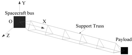
Table 150 order modes
Order | Frequency (Hz) | Description |
1 | 0.058 | First bend mode a |
2 | 0.129 | First bend mode b |
3 | 0.146 | First torsion mode |
4-50 | 0.347-0.73 | A large number of local modes |
The modal analysis results show that the large-scale flexible spacecraft has the characteristics of low and dense frequency. In the results of finite element analysis, there are two first-order bending modes in the plane, and they do not correspond strictly to the -axis and -axis directions. The frequencies of the 4th to 50th order modes are between 0.347Hz and 0.73 Hz, which contains a large number of local modes of the reflector surface, as well as the combination of high-order bending and torsion. We assumed that the modal damping of each order 0.005.
2.2. Equivalent model of piezoelectric actuator
The main body of the piezoelectric actuator rod is a cylinder structure with a length of 250 mm, an inner diameter of 10 mm and an outer diameter of 20 mm, which is stacked by piezoelectric ceramic plates. The elastic modulus in the driving direction 48.31 GPa, and the piezoelectric strain coefficient in the driving direction 5.93×10⁻¹⁰ m/V. The number of piezoelectric plates 1250 and the voltage limit is 120 V. The output displacement of piezoelectric actuator under zero stress state is shown in Eq. (1):
If the displacement caused by the driving voltage of piezoelectric actuator is equivalent to that caused by tension at ends, the equivalent tensile force is shown in Eq. (2):
The equivalent relationship between the force at ends and the load voltage at ends is shown in Eq. (3):
where is the degradation rate of actuator performance caused by factors such as the bonding and electrodes, 1, defined as 0.9; is the proportional coefficient of equal force and driving voltage, 135.
2.3. Multi-subsystem control model
The whole governing equation of large-scale flexible space structure is:
where is the total mass matrix, is the total damping matrix, is the total stiffness matrix, is the control force and is the external disturbance.
Assuming that the large-scale flexible space structure is divided into substructures, the governing equation of each substructure can be written in a similar form as the Eq. (5):
where is the force from the adjacent subsystems, which could be considered as an external disturbance of current subsystem.
3. Distributed control
3.1. Design and layout of actuators and sensors
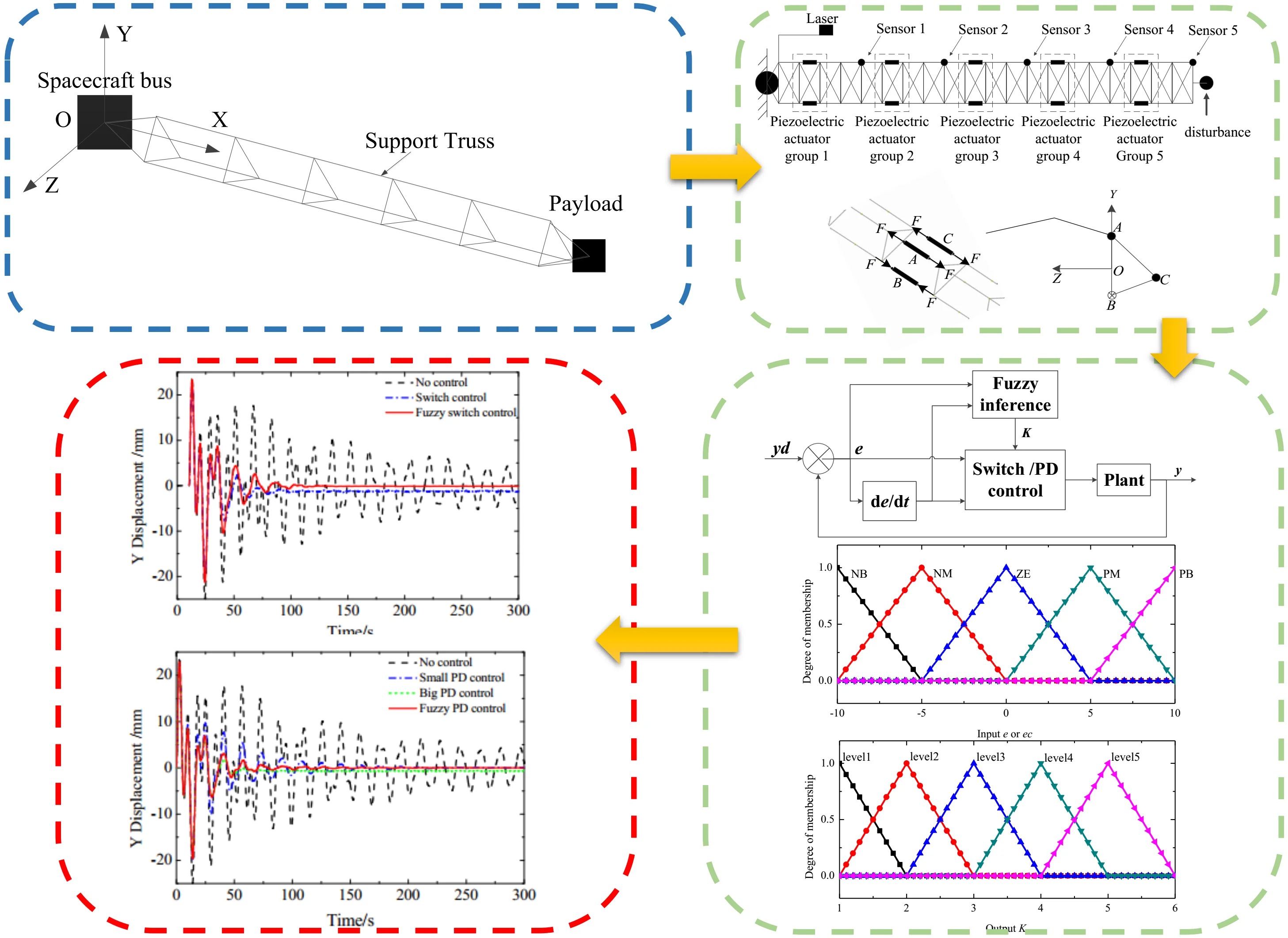
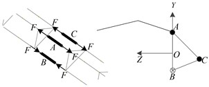
As shown in Fig. 2, it is assumed that the -direction and -direction displacements at the end of each span on the triangular support truss of antenna can be measured by sensors 1-5. The piezoelectric actuator group is arranged in the middle of each span, as is shown in Fig. 2. Each piezoelectric actuator group is composed of three actuating rods, as shown in Fig. 3. The A and B bars are loaded with opposite voltage to suppress -axis vibration. The C bar is loaded with voltage to suppress -axis vibration. According to the -direction and -direction displacement information transmitted by sensor , the actuator group executes control instructions and suppresses the vibration of each module. The disturbance excitation occurs at the end of the payload.
Fig. 2Actuators and sensors layout
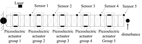
Fig. 3Working diagram of actuators
3.2. Switch control and PD control
The control system of switch control method is simple. It doesn’t need accurate dynamic model. When the velocity is positive, the maximum voltage value is set at the ends of the piezoelectric actuator to produce the force, which opposite to the velocity direction. When the velocity is negative, the voltage at the ends of the piezoelectric actuator switches to reverse rapidly, and the speed of the system tends to zero gradually. Actually, the piezoelectric actuators can only load positive voltage. The control rate is shown in Eq. (6):
where is the displacement of node at the th substructure, and is the velocity of node at the th substructure.
PD control also does not require an accurate dynamic model. The error between the original position and the measured position is . Taking as the input, proportional component can control the deviation rapidly. Differential component reflects the change rate of deviation, which introduces an early correction signal to speed up the system action and reduce the adjustment time before the deviation is too large. The control rate is shown in Eq. (7):
Since the actuators and sensors are considered as the collocated pairs, the input matrix is equal to the transposition of the output matrix . So, the Eq. (5) is rewritten by the input fore calculated by the switch control rate Eq. (6) or the PD control rate Eq. (7):
The original dynamical system is obviously asymptotic stable, as well as 0, 0, and 0. Since the > 0, > 0, > 0, and ≥ 0, the Eq. (8) and Eq. (9) are therefore asymptotic stable, as well as , and . In the actual engineering application and the following simulation tests, the sensors and the actuators cannot be collocated strictly in the same position, and the control command is discrete. Therefore, the spillover is easy to occur if the parameters are too large. Then, we proposed the improved method by fuzzy logic system.
3.3. Control method based on fuzzy logic system
Through the fuzzy logic system, a coefficient is set on the parameters of the original control rate, and the selection of is determined by the fuzzy logic system, as shown in Fig. 4. When the displacement disturbance and the rate of change are large, is taken as the large value. The control voltage calculated by the original control rate can maximize the actuating capacity of actuators. When the displacement disturbance e and the rate of change are small, is taken as the small value to ensure the stability and accuracy of the control.
Fig. 4Schematic diagram of controller structure
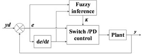
Table 2Fuzzy rule table of K
/ | NB | NM | ZE | PM | PB |
NB | level5 | level4 | level3 | level4 | level5 |
NM | level4 | level3 | level2 | level3 | level4 |
ZE | level3 | level2 | level1 | level2 | level3 |
PM | level4 | level3 | level2 | level3 | level4 |
PB | level5 | level4 | level3 | level4 | level5 |
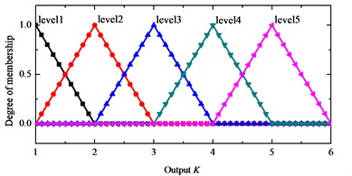
The input of fuzzy inference system are the end ( direction or direction) displacement and the change of rate which reflect the overall disturbance. The output variable is the parameter . The input value is transformed into the domain of discourse [–10, 10] and is transformed into the domain of discourse [–10, 10] by the scale change factor and . The set of 5 language description variables corresponding to and is {negative large: NB, negative medium: NM, zero equal: ZE, positive medium: PM, positive large: PB}. Output is in the domain of discourse [1, 6], and the corresponding set of 5 language description variables is {level 1, level 2, level 3, level 4, level 5}. The triangular membership function ‘trimf’ is used to construct the membership function, shown in Fig. 5 and Fig. 6. 5×5 fuzzy rules are designed, as shown in Table 2. The Mamdani fuzzy controller with the above input and output rules is designed in the Matlab fuzzy toolbox. We use the maximum-minimum fuzzy synthesis formula, and the defuzzification method of area center.
Fig. 5Input e/ec membership function
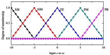
Fig. 6Output K membership function
4. Simulation
The commercial software Patran and Nastran are used for finite element analysis. After the interactive files which are imported into Adams, the positions of sensors and actuators can be set up, and the numerical simulation model interacting with MATLAB is established. The whole control simulation system is built in Simulink. The control plant is a multiple-input multiple-output systems with 16 inputs, 10 outputs, the inputs include 1 disturbance input, 5 actuator modules and 15 control inputs. The outputs include 5 sensor positions and 10 displacement outputs.
It is assumed that there is a pulse excitation at the end of the payload at the initial zero moment, and the direction is perpendicular to the axis. If the excitation is a 20 step signal lasting for 1 second, the displacement disturbance of about 25 mm in direction and direction at the sensor 5 can be caused. One second after the disturbance, we turn on the controller.
If the control is not applied, the -direction and -direction displacement response curves at sensor 5 are shown in Fig. 7. In the simulation time of 300 seconds, the displacement disturbance attenuates slowly. The response of -axis displacement is transformed by FFT, and the result is shown in Fig. 8. The first frequency is 0.058 Hz, the second frequency is 0.13 Hz, and there is a dense frequency region between 0.3 Hz and 1 Hz, which is consistent with the results of finite element modal analysis.
By using the switch control and fuzzy switch control method, the displacement response in and directions at sensor 5 are simulated as shown in Fig. 9 and Fig. 10. The results show that the vibrations of large-scale flexible space structure can be suppressed by the above methods. The switch control method improved by fuzzy logic system has better control precision and low steady-state error.
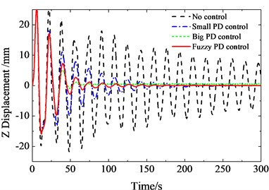
By using the PD control and fuzzy PD control method, the displacement response in and directions at sensor 5 are simulated as shown in Fig. 11 and Fig. 12. When the parameters of PD control are small, the attenuation time is longer. When the parameters of PD control are big, there is an obvious spillover at high-order mode. The results show that the method improved by fuzzy logic system has better control precision and low steady-state error.
Fig. 7Free attenuation displacement response in Y and Z directions at sensor 5
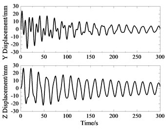
Fig. 8Spectrum of Y-direction displacement response at sensor 5
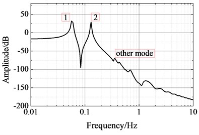
Fig. 9Displacement response in Y direction at sensor 5
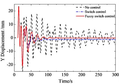
Fig. 10Displacement response in Z direction at sensor 5
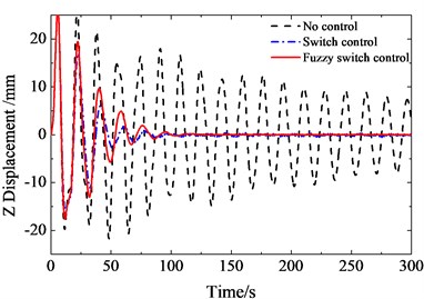
Fig. 11Displacement response in Y direction at sensor 5
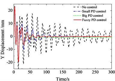
Fig. 12Displacement response in Z direction at sensor 5
5. Conclusions
In this paper, a detailed distributed control method with piezoelectric actuators on the main supporting structure is proposed. Based on fuzzy logic system, the improved method has better control precision and is intensive to the spillover problem because of the adaptive adjustment of control parameters. The simulation results show that the distributed control has good vibration suppression effect for large-scale flexible spacecraft.
References
-
Gardonio P., Bianchi E.,Elliott S. J. Smart panel with multiple decentralized units for the control of sound transmission. Part I: Theoretical predictions. Journal of Sound and Vibration, Vol. 274, Issue 1, 2004, p. 163-192.
-
Gardonio P., Bianchi E.,Elliott S. J. Smart panel with multiple decentralized units for the control of sound transmission. Part II: design of the decentralized control units. Journal of Sound and Vibration, Vol. 274, Issue 1, 2004, p. 193-213.
-
Gardonio P., Bianchi E.,Elliott S. J. Smart panel with multiple decentralized units for the control of sound transmission. Part III: control system implementation. Journal of Sound and Vibration, Vol. 274, Issue 1, 2004, p. 215-232.
-
Jiang J. P., Li D. X. Robust H-infinity vibration control for smart solar array structure. Journal of Vibration and Control, Vol. 17, Issue 4, 2011, p. 505-515.
-
Hu Q., Su L., Cao Y., et al. Decentralized simple adaptive control for large space structures. Journal of Sound and Vibration, Vol. 427, 2018, p. 95-119.
-
Rao S. S., Liu Q. Fuzzy optimal controller design with application to fuzzy modeled structures. AIAA Journal, Vol. 46, Issue 4, 2008, p. 1864-1873.
-
Xu R., Li D. X., Jiang J. P. An online learning-based fuzzy control method for vibration control of smart solar panel. Journal of Intelligent Material Systems and Structures, Vol. 26, Issue 18, 2015, p. 2547-2555.
About this article

