Abstract
On-site machining is a specific domain where damaging vibrations can be generated by the dynamic interaction between the tool and the workpiece. These vibrations are often the cause of the degradation of the machined part and the cutting tool. Therefore, it is necessary to suppress and/or control this phenomenon. For this purpose, the design of the magnetorheological damper, which can be used for the semi-active control of the on-site machining vibrations, is presented in this paper. Then, we investigate experimentally the efficiency of our conception through tests with a light milling portable machine frequently used by on-site machining. The results of the experiments show a reduction in vibrations of 20 % and 40 % at low frequency and high frequency, respectively. It is highlighted that the magnetorheological damper has good effect on on-site machining process.
Highlights
- Design of a test bench for vibration measurements of a portable milling machine used for on-site machining.
- Design and test experimentally a magneto-rheological damper that provide effective reduction at low and high frequency.
- We found at low frequency, around 5 Hz, a 20% reduction in vibration intensity.
- We found at high frequency, around 1 kHz, a forty percent reduction in vibration intensity without important drawbacks.
1. Introduction
In today’s industrial world, corrective and preventative maintenance play a key role by limiting the production losses. This is even more so if industrialists do not have the possibility to move their defective equipment to rehabilitate it. To overcome these difficulties, one activity exists: the on-site machining. It consists of carrying out all classical types of machining operations to repair and restore non-removable parts of equipment, directly on industrial plants, using portable machines.
However, due to the lightness of these portable machines, important vibrations appear. These vibrations are usually caused by the degradation of the dynamic interaction between the cutting tool and the machine sample [1-3]. It becomes necessary to control or eliminate the appearance of this phenomenon.
To achieve it, the semi-active damper based on Magneto Rheological (MR) fluid put forward a very interesting compromise between high performance and low power consumption [4, 5]. These devices have adjustable properties and damping parameters that can be controlled to optimize their behaviour over a wide range of excitation frequencies in real time [6, 7]. Under an external magnetic field, the MR fluids viscosity increases, with a response time lower than few milliseconds.
The aim of the Authors of this paper is to present the design and performance of a new MR damper. This MR damper is specially designed to damp low and high frequency. We then presented the performance on a new experimental setup applied to the on-site milling machine. This activity is a few represented in the literature. The MR damper efficiency has been evaluated through the triaxial accelerometer response. Finally, we discuss the results and provide the future development.
2. Methods
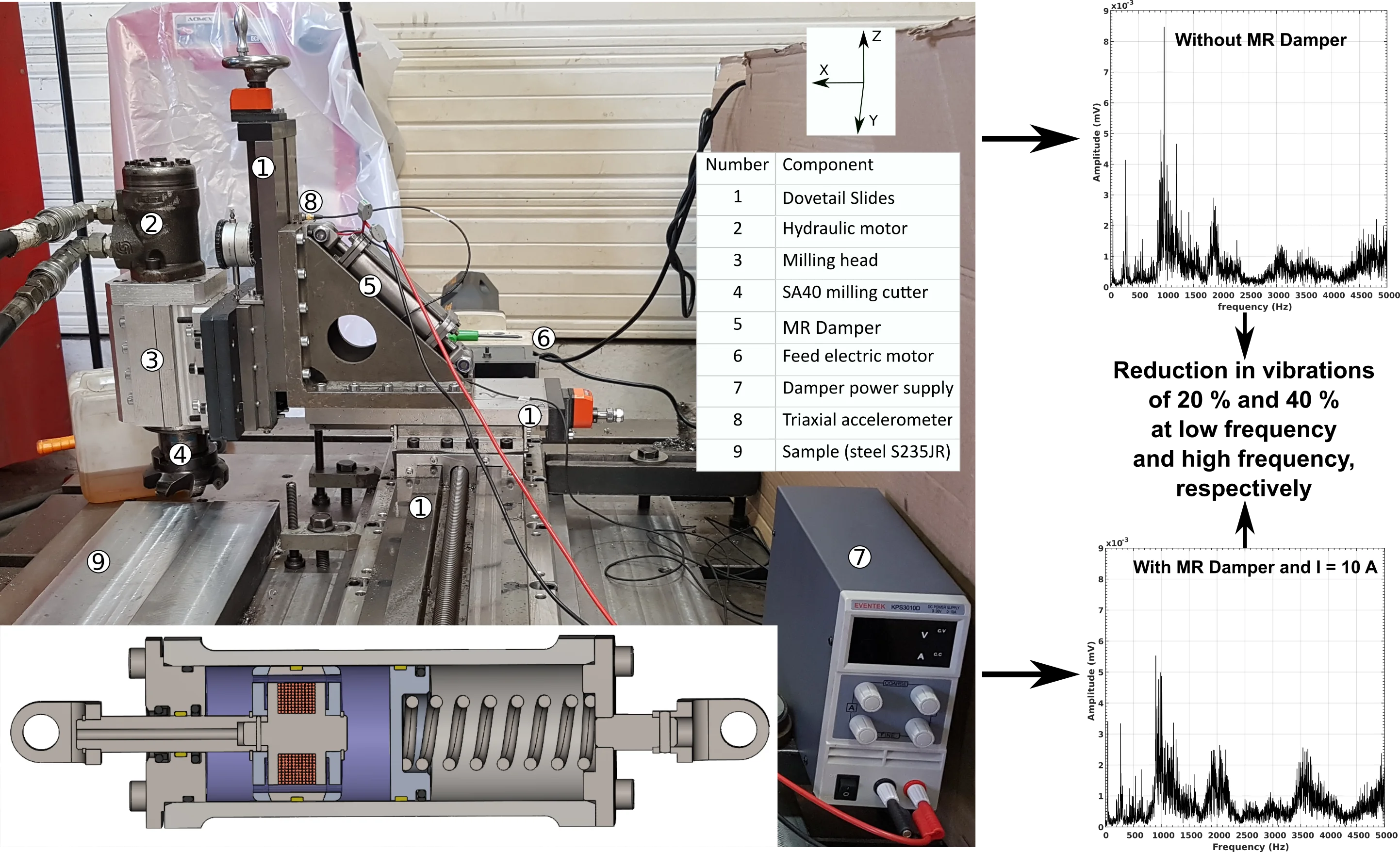
A setup to evaluate the efficiency of the Magneto Rheological (MR) damper prototype was established. A picture is shown in Fig. 1 where we have a light milling machine frequently used on on-site machining and a machined sample S235JR fixed by six welding points on a common plate. The light milling machine is equipped with three dovetail slides (, and axis) of length 1 250, 300 and 300 mm, respectively. The axis is equipped with a demountable electric power feed ALGS-AL310S. The and axis each have a manual feed. The milling head was fixed on the axis dovetail slide. This head was powered by an OMP100 hydraulic motor that drives a milling cutter SA40. The cut was made with seven Mitsubishi MP9120 machining inserts. To be sure of the cutting experimental conditions, we adjusted the position of each light milling machine component with a Faro laser tracker [8].
Fig. 1The experimental setup for the magnetorheological damper tests
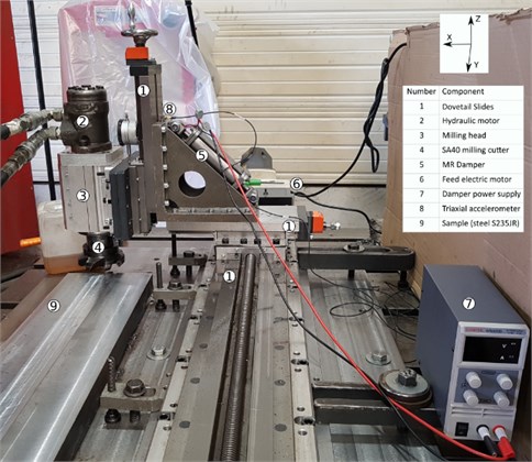
The light milling machine is mounted with our new MR damper [9] (Fig. 1(5)) between the and dovetail slides. To set the MR Damper in vibration control mode, an electrical power supply, Eventek KPS3010D, is used (Fig. 1(7)). The applied current is from 0 to 10 A. Finally, the displacement responses of the system are acquired thanks to a Brüel and Kjær triaxial accelerometer 4535B. The data acquisition and treatment are realized with a Labview compact DAQ chassis cDAQ-9174, a 9122 module and a dedicated module for sound and vibration analysis.
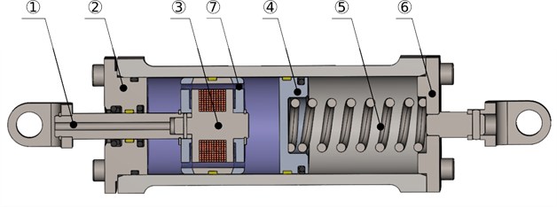
The MR damper works in flow mode as shown in Fig. 2. In the flow mode, the only external force comes in the form of pressure difference in the direction of the fluid flow. The damper is 230 mm long in its nominal position and has ± 12 mm shock absorber stroke. The main cylinder includes a floating piston, an electromagnet, a volume compensation spring, and MR fluid. MR fluid MRHCCS4-B 80 %, which was obtained from the Liquid Research firm, is used in the damper [10]. The MR fluid valve is contained within the piston and consists of an annular flow channel with 2.5 mm gap. The total axial length of the flow channel is 29 mm which exposed to the applied magnetic field. Viscosity of MR fluid in the valve will be increased by increasing the electric current through the electromagnet, thus resisting the MR fluid flow through the valve, and increasing the damping force of the MR damper. Moreover, the design of this MR damper has been also specially developed to dampen small deformation at high frequency. Indeed, the pistons as well as the rod require a good guiding system to limit friction as much as possible. We have therefore chosen PTFE guide rings which offer interesting performance and can withstand speeds of 15 m.s-1. With our design choices, it is calibrated to damp up to 1 mm of deformation at high frequencies.
Fig. 2Sectional view of the MR Damper. (1) piston rod, (2) rod mounting bracket, (3) piston heart with an electromagnet, (4) floating piston, (5) volume compensation spring, (6) flange, (7) MR fluid annular flow channel. The violet area represents the MR Fluid MRHCCS4-B 80 %
We carried out three tests, one without damper and two with damper for the experimental conditions described on Table 1. To process the data collected by the accelerometer, we used the Labview sound and vibration package. We used the Voltage versus Time representation. Then we applied a high pass filter and a Fast Fourier Transform (FFT). Finally, the results were showed in the frequency domain.
Table 1Conditions for the different experiments
Experiment | Presence of the MR damper | Current (A) | Depth of cut (mm) | Spindle speed (tr.min-1) |
#1 | No | – | 1 (± 0.02) | 350 (± 5) |
#2 | Yes | 0 | 1 (± 0.02) | 350 (± 5) |
#3 | Yes | 10 (± 0.01) | 1 (± 0.02) | 350 (± 5) |
3. Results
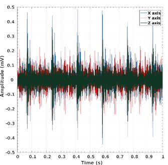
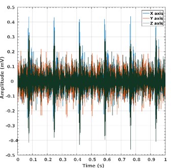
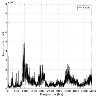
Thanks to the experimental system, we have acquired the signals corresponding to the vibrations of the system throughout the regular machining process. These data acquired by the triaxial accelerometer are presented in Fig. 3(a) with a plot of the amplitude as a function of the time. Shocks are observed every 0.184 seconds. These represent the moment when the insert enters the material and proceed to machine it. The average shock amplitudes along the and axes are approximately 0.44 and 0.29 mV, respectively. After application of the high-pass filter, the data in the frequency range are shown in Fig. 3(b). Several high amplitude peaks are present. However, we will focus on the most important one around 967 Hz, which is the maximum amplitude, around 8.47×10⁻³ mV.
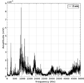
Fig. 4(a) shows the same machining process but with the addition of the MR damper. However, the MR damper is not supplied with power. The average shock amplitudes of the and axis on the time domain are around 0.42 and 0.30 mV, respectively. On the Frequency domain, the amplitude of the previous peak decreased down to 6.42×10⁻³ mV (Fig. 4(b)). In addition, two more peaks appear at 915 and 944 Hz with an amplitude of 6.93 and 6.81×10⁻³ mV, respectively.
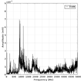
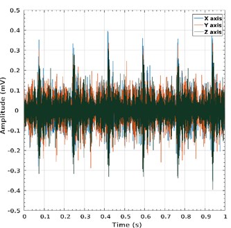
Fig. 5(a) shows the same results from machining process but with the addition of the MR damper. In this experiment, the MR damper is supplied with a current of 10 A. The average shock amplitudes of the and axis on the time domain are around 0.36 and 0.25 mV, respectively. On the Frequency domain, multiple peaks around 980 Hz appear at the average amplitude of 4,87×10⁻³ mV (Fig. 5(b)). The more important one has an amplitude of 5.52×10⁻³ mV at 901 Hz.
Fig. 3Data acquired by the triaxial accelerometer during the regular machining process. The MR damper is not installed for this experiment: a) X, Y and Z axis amplitude in relation to the time acquired for one second; b) Z-axis amplitude in the frequency domain for the same signal
a)
b)
Fig. 4Legend identical to Fig. 3, except for the MR damper which was installed on the light milling machine with a 0 A current supply
a)
b)
Fig. 5Legend identical to Fig. 3, except for the MR damper which was installed on the light milling machine with a 10 A current supply
a)
b)
4. Discussion of tests results
From the experiments, we can observe that shocks are present every 0.184 seconds. These represent the moment when the insert enters the material and proceeds to machine the S235JR material. The frequency of these shocks is 5.43 Hz. At this frequency, a 20 % reduction in vibration intensity occurs for the -axis. It is 16 % for the -axis. This is a significant gain that our shock absorber allows for these conditions.
It is also observed that the damping occurs at very high frequency. Indeed, at around 1 kHz and for the -axis, a 40 % reduction in vibration intensity happens. It is a significant benefit, which confirm our conception choices. On the other hand, however, we observe a widening of the peak which is common for the damping.
Unfortunately, there are other negative consequences. At high frequencies, especially around 2.1 and 3.6 kHz, several broad-band peaks of moderate intensity are slowly appearing. At low frequencies, the same situation appeared at around 600 Hz.
5. Conclusions
This paper presents the design of a test bench for the vibration measurement of a portable milling machine used for on-site machining. In addition, we also present a MR fluid damper specially designed to dampen low and high frequencies. It is investigated experimentally that the proposed MR damper provide effective reduction of vibration at low and high frequency bands that are 20 % and 40 %, respectively. However, we have not yet characterised its total frequency response function. This will come later by the development of a dynamic behaviour with a Bouc-Wen model. Finally, this damper will play its full role for on-site machining activity once a semi-active control system has been set up.
References
-
Budak E. Altintas Y. Analytical prediction of chatter stability in milling – part i: general formulation. Journal of Dynamic Systems, Measurement, and Control, Vol. 120, Issue 1, 1998, p. 22-30.
-
Quintana G., Ciurana J. Chatter in machining processes: A review. International Journal of Machine Tools and Manufacture, Vol. 51, Issue 5, 2011, p. 363-376.
-
Thien-Phu Le M., Gagnol V., Sabourin L. Modal identification of a machine tool structure during machining operations, International Journal of Advanced Manufacturing Technology, Vol. 102, 2019, p. 253-264.
-
Kotrane A. Design, Realisation and Dynamic Characterisation of a Magneto-Rheological Damper. Doctoral Dissertation, École De Technologie Supérieure, 2007, (in French).
-
Ulasyar A., Lazoglu I. Design and analysis of a new magneto rheological damper for washing machine. Journal of Mechanical Science and Technology, Vol. 32, Issue 4, 2018, p. 1549-1561.
-
Pour D. S., Behbahani S. Semi-active fuzzy control of machine tool chatter vibration using smart MR dampers. The International Journal of Advanced Manufacturing Technology, Vol. 83, Issues 1-4, 2016, p. 421-428.
-
Prabhu L., Satish Kumar S., Dinakaran D., Jawahar R. Improvement of chatter stability in boring operations with semi active magneto-rheological fluid damper. Materials Today: Proceedings, 2020, https://doi.org/10.1016/j.matpr.2020.04.651.
-
3D measurement, imaging and realization technology for 3D Metrology, https://www.faro.com.
-
Langrand C., Masset M. Intelligent fluid damper for a portable machine tool. FR. Provisional Patent Application Ser. No. FR 20 10575), French Patent and Trademark Office Regimbeau, 2020, (in French).
-
Liquids Research Limited, http://www.liquidsresearch.com/.
About this article

