Abstract
Control devices can be used to dissipate the energy and attenuate undesirable vibration on engineering structures. Recently, to mitigate the response of structures during the earthquakes and high intensity winds, semi active control has been widely used. MR dampers are semi active control devices that are managed by sending external voltage supply. A new adaptive fuzzy logic controller (FLC) is introduced to manage MR damper intelligently. Furthermore, a novel evolutionary algorithm of particle swarm optimization (PSO) was used to optimize the placement and the number of MR dampers and sensors in the sense of minimum resultant vibration magnitude. Numerical efforts were considered to validate the efficiency of proposed FLC. In designer’s point of view, the proposed PSO-FLC controller can find the optimal solutions during a reasonable number of iterations. Finally, results demonstrate that proposed PSO-FLC controller could find the appropriate control force and attenuates the excessive responses in several buildings.
1. Introduction
Over the past three decades, a great deal of interest has been concentrated on using of structural protective systems in order to mitigate the effects of environmental hazards such as earthquakes and high intensity winds. To enhance structural safety and serviceability in designing of structures, the dissipation of input energy and attenuation of vibration are crucial. Control systems could have been used in smart structures to mitigate the vibration [1]. Structural control methods are the most recent strategies for this purpose, which can be classified as active, semi-active, passive, and hybrid control methods [2]. Although, active control systems have been designed and installed in full-scale structures, but it needs more developing to solve the robustness problems. Passive devices have acceptable results in mitigating of the structure responses, but the lack of adaptability with vibration conditions is one of the problems in robustness of these structures. Moreover, with emergence of smart materials, the interest of applying a resistance force with semi active control has been introduced. A semi-active control system is a system with devices that cannot input energy into the system [3]. MR dampers are new semi active devices which have a major potential to improve the vibration control technology in new smart structures. The most important characteristic of MR damper is the reliability of passive control systems that can preserve the versatility and adaptability of active control systems. The first development of MR fluids and devices was done by Jacob Rabinow at the US National Bureau of Standards in the late 1940s [4, 5]. In the last few years, 200 kN MR dampers have been constructed and tested [6-10]. Spencer et al. developed a mechanical model which based on the Bouc-Wen hysteresis model that describes the dynamic behavior of MR dampers [11]. Recently, numerous full-scale structures have been equipped with supplemental damping devices to mitigate the responses [12]. The usage of MR damper in civil engineering structures is more progressive and the optimal design scheme should be proposed. Optimal damper placement should be done since by different arrangement of dampers, higher control levels may be achieved. Furthermore, it is important to reduce the costs, which are related to the set up and maintenance of the semi active systems. On the other side, the minimum vibration magnitude is a crucial criterion for the effectiveness of control systems [13]. Several studies perused the optimal placement of dampers but none of them has paid attention to find the optimal MR damper placement and sensors as two discrete subjects. PSO is a novel stochastic evolutionary algorithm, which has been proposed recently [14-17]. It is based on the sociological behavior through the movement and behavior patterns of bird flocks and fish schools. A modified binary particle swarm optimization (BPSO) is used to obtain the optimal placement of MR dampers and sensors with the minimum number of MR dampers. Classical optimal control [18] and instantaneous optimal control [19] have been applied to the structures with known structural parameters. However, they require some previous knowledge or precise information about the characteristics of a structure that its mathematical model is going to be constructed. Moreover, control schemes such as Linear Quadratic Gaussian (LQG) optimal control necessitate a solution for heavily constrained optimization problems [20]. To overcome those obstacles, many studies have focused on soft-computing techniques such as fuzzy logic [21] and neural networks [22]. Recent studies demonstrated that adaptive controllers are more reliable and effective [23-25].
The focus of this study is semi-active adaptive optimal control of 2D benchmark linear buildings under seismic excitation, based on the fuzzy logic controller (FLC). Effective fuzzy logic controller used to improve the MR damper efficiency and consuming less energy [16]. Fuzzy logic controller manages the MR damper characteristic by sending electrical input current. In the previous Fuzzy logic controller, input data are the relative velocity and displacement of MR damper piston. In this study, separate sensors were used independently to transmit the absolute displacement and the velocity of stories. To the Author’s best knowledge, there is no published research on semi active control of high-rise building with MR dampers by using separately sensor installation to manage the control forces. For this purpose, FLC calculates the magnetic field inducing current regarding to the displacement and the velocity of the floor, which were transmitted by the sensors. The inducing current should be sent to each damper. The proposed PSO-FLC controller demonstrate its efficiency with less computational burden by using particle swarm optimization to find the optimal placement and the number of dampers and sensors, simultaneously.
2. Problem statement
The main question in designing of structural control systems is which control strategy should be utilized. If control algorithm is time consuming with complexity, the time delay issues lead to reducing the reliability of control system. A feedback control strategy that minimize the computation time and do not require any adjustment during the environmental hazards will have more efficiency and reliability. FLC gathers these characteristic to the control strategy. The proposed FLC manages the MR dampers mechanical behavior by sending external voltage supply. Few studies pursued the optimal control of structures by using optimal FLC [26, 27]. None of these studies have paid attention to find the optimal MR damper and sensors as two independent subjects. In this paper, sensors placement were determined independent of dampers placement. Therefore, FLC inputs changed to absolute displacement and velocity of stories which sensors were placed. Because of dynamic behavior of MR damper, the piston velocity and acceleration affect to the external forces of damper. So, more stories were involved to determining the damper forces, with same number of sensor and damper. 3, 4 and 8 Story shear buildings were investigated to show that the proposed FLC leads to better results than traditional algorithms. In addition to reducing the structural vibration magnitudes, the control system should be enhanced simultaneously to minimize peak of control forces. Therefore, a model of a combinational optimization problem consists of three objective functions to be minimized. Search space is the placement of dampers and sensors. The number of utilized MR dampers and sensors are constraints for optimal placement problem. After some necessary modification on the main theory of particle swarm optimization (PSO). The FLC-PSO is used to deal with MR damper and sensor optimization problem.
3. The equations of motion
In the state space, the equations of motion for the n-story structure can be described as follows:
where:
where , and are displacement, velocity and acceleration vectors of the structure, respectively. , and represent the mass, stiffness and damping matrices of the structure, respectively. is external force and is output vector of the state space model. shows the damper location matrices. and are the state space and output vector, respectively. Control force is considered as a function of displacement and velocity responses of the structure in closed loop control which determined by a fuzzy logic controller. The main problem is designing a control system to determine the optimum number and position of dampers and sensors.
4. The dynamic behavior of mechanical model of MR damper
Magneto-rheological fluids are a kind of controllable fluids, which can respond to an applied field with a fast change in their rheological behavior. The essential characteristic of MR fluids is their ability to reversibly change from free flowing, linear viscous liquids to semi-solids fluids having a controllable strength when exposed to a magnetic field in a few milliseconds. MR fluid dampers have high dynamic range, large force capacity, robustness and reliability. MR dampers with a capacity of 20 tons, have been tested and designed since 1996 [28]. A recently reported model is able to predict the response of MR damper over a wide range of loading conditions and command voltages. In this study, finite number of 20-ton MR dampers were used. These devices are used as semi-active actuators in which the voltage is updated by a fuzzy logic controller. The mechanical model of MR damper which is proposed by Spencer et al. [29] was used to reproduce the force of the damper, in each time step. The governing equations of the produced are listed below:
where:
where is the internal displacement of MR damper and is the damper displacement in the direction. , and values of MR damper were experimentally obtained by Yang [30] and ‘’ is the input current, in each time window. To adjust the experimental data, the additional variables are taken constant as 0.18 m, 617.31 N/m, 37810 N/m, 2679 m-1, and 647.46 m-1, 10. To validate the dynamic behavior of this mechanical model with experimental studies, a first order filter was also used to correctly model the dynamics of MR fluid for reaching to rheological equilibrium [27]:
The time delay associated with the MR damper and closed loop response together is less than 10 ms [31]. This time delay is far from the first period of two structures. So, the effect of time delay can be ignored. In addition to the velocity and acceleration of the piston of MR damper during the each time step, the electrical input current had a significant rule to determining the damper force. Fuzzy logic controller managed the input current. The governing rules will be discussed in the section 5. Mechanical model and schematic figure of MR damper were presented in Fig. 1. Some different studies related with other control methods were employed from MR dampers [32-33].
Fig. 1Mechanical model and schematic figure of MR damper [11]
![Mechanical model and schematic figure of MR damper [11]](https://static-01.extrica.com/articles/17802/17802-img1.jpg)
![Mechanical model and schematic figure of MR damper [11]](https://static-01.extrica.com/articles/17802/17802-img2.jpg)
5. Fuzzy logic control
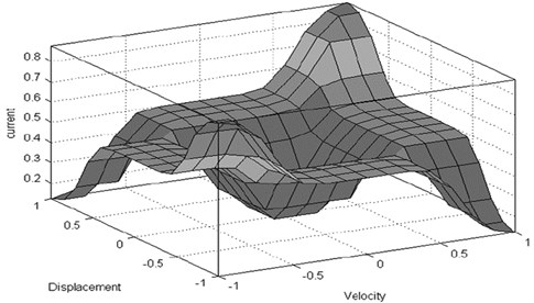
The performance of traditional controllers (e.g., linear quadratic Gaussian, , etc.) fully depends on the accuracy of system dynamics modeling. Complex structural systems have nonlinearities and uncertainties in both structural properties and the magnitude of the loading. It is difficult to identify an accurate dynamic model for designing the traditional controller. The new control algorithm can improve the modeling imprecisions and uncertainties without necessitating any heavily constrained optimization problems to solve. The FLC (Fuzzy Logic Control) is based on the fuzzy set theory [21]. FLC essentially consists of four components to simulate the logical reasoning of human beings. These components were named: fuzzification interface, rule base, decision making and defuzzification interface. In this study, to deal with the imprecision and uncertainty which was not determined in the design process, an intelligent FLC controller has been introduced. A FLC can be incorporated into a closed-loop control system similar to conventional feedback controllers. An independent sensor for each MR damper was determined. Hence, the velocity and displacement of the sensor are the input variables. The output variable of FLC is inducing current, which governs the MR damper control force. Range of Membership functions for the input variables is [–1, 1] and for the output variables is [0, 1]. When the velocity and the displacement of the damper are in the same directions, the rule-bases use a major current to generate a large control force. If they are in different directions, no significant control force needed. Gaussian curve membership function was used. The sensors signal convert into linguistic fuzzy values through the fuzzification process. The Mamdani-type fuzzy logic was considered which is well suited for control systems. The scale factor and quantification factor is very important to determine the control force. The selection of the fuzzy functions, fuzzification and de-fuzzification were chosen by trial and error to achieve the best responses. The membership functions for both input and output variables were shown in Fig.2. The details of inference rules were shown in Table 1. Resulted mechanical model of MR damper was shown in Fig.3. Each of the input and output fuzzy variables are defined in the fuzzy space, in the form of nine linguistic values namely ND (Negative Displacement), ZD (Zero Displacement), PD (Positive Displacement), NV (Negative Velocity), ZV (Zero Velocity), PV (Positive Velocity), Z (Zero), S (Small) and L (Large).
Table 1Inference rules used in the proposed FLC
NV | ZV | PV | |
ND | L | S | Z |
ZD | S | Z | S |
PD | Z | S | L |
Fig. 2Membership functions used for input and output variables of the proposed FLC
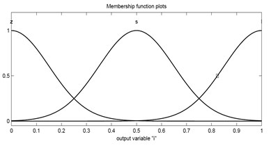
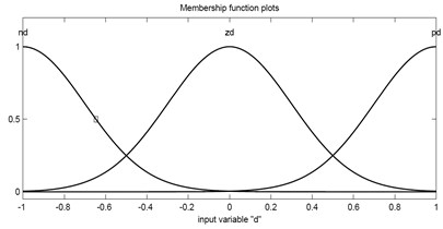
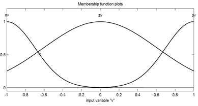
Fig. 3Fuzzy logic controller
6. Modified binary particle swarm optimization
Particle swarm optimization (PSO) is a stochastic population technique based on optimization approach [14]. PSO is an evolutionary computation algorithm through individual improvement plus population cooperation and competition, which is derived from social-psychological theory. PSO is a parallel search technique due to a group of particles exploration. Since many optimization problems were set in discrete space, a discrete binary version of particle swarm optimization was proposed by Kennedy and Eberhart [17]. PSO maintains a swarm of particles such as fish schooling and bird flocking, where each particle represents a potential solution to an optimization problem. Particles fly around in a multi-dimensional search space. PSO generates a swarm of random particles and searches for the optimal solution by updating each iteration. Based on the fitness function, the solution provides a quantitative value of the particle’s location. A particle status in the search space is characterized by two factors: position and velocity. The position and the velocity of th particle in the d-dimensional search space can be represented as:
During the movement, each particle adjusts its position according to its own experience and the experience of its neighboring particles. The personal best position, local best () is the best solution, which is found in the course of the flight. The best position of the whole flock, , is the global best solution. The modification of the velocity, , can be represented by Eq. (7):
where is the inertia weight, 1, 2,…, indicates the index of particles, 1, 2,…, indicates the current generation number, is the maximum number of generation, and represent the random numbers between [0, 1], represents the best ever position of particle i and corresponds to the global best position in the swarm up to iteration . and are trust and coefficient parameters which is assumes 2. and are two independent random numbers uniformly distributed in the range [0; 1]. is called the inertia factor which is often in the range [0.1, 0.9]. Previous studies show that if decreases linearly during the exploration process, it will improve the convergence performance greatly. is expressed as follows:
where and are called maximum and minimum weight, respectively. is the current generation number and is the maximum number of generation. In each generation, particles position change is defined by the following equation:
where is a logistic function that governs the changes in the position of particles. These changes are defined by the following rules:
where is a parameter, which can change linearly between an initial and a final value in each iteration. Then a new value of is calculated as:
where is the iteration number and is the maximum number of allowable iterations. and are 0.25 and 0, respectively. is an incremental parameter which allows the particles to move toward the search space in the initial iterations. In the next iterations, gradually increases and simultaneously the probability of changing the particle position decreases. Hence, more velocity is required to move further in the search space. In the first iteration, algorithm allows the particle to move further in the search space because the global best and the local best have their starting values and they are not reliable. When the algorithm goes further, the global best and the local best are more reliable and the probability of changing the particle positions in the search space decreases.
7. Numerical simulations and results
In numerical results, the state-space model of structures and FLC were used. The components of numerical simulations include the building models, MR dampers, controllers, sensors and the ground motion time history of acceleration. The State-space representation was used to predict the dynamic behavior of structure in numerical simulations in MATLAB [34].
7.1. The generation of the fuzzy logic controller and its effectiveness
To demonstrate the effectiveness of the proposed fuzzy logic controller, the state-space model of a structure was determined and the mechanical model of MR dampers were used. Finally, the responses of the structure during the time history of acceleration were compared with the passive-off and passive-on responses. For the current studies, three fitness functions were defined as the following equations:
where is the displacement of the each floor, is the inter-story drift, is the absolute acceleration of the floors and RMS shows the root mean square of variables. The superscript denotes the case where the MR dampers are operated in the passive-off mode and no command voltage is sent to the dampers. The final case is the fuzzy logic control which is noted by the abbreviation FLC. The operational range of each MR damper is 0 to 1 V. A three-story shear building was chosen to determine the effectiveness of fuzzy logic controller. The building properties are listed in Table 2.
Table 2Inference rules used in the proposed FLC
Floor mass | 50000 Kg |
Floor stiffness | 20000 kN/m |
Damping coefficient () | 1 % |
A near-fault forward-directivity El-Centro time-history of N-S acceleration was used to excite the benchmark structures. Fig. 4 illustrates ground acceleration for station H-E0230.
After the simulation, PSO with respect to three fitness functions shows that one MR damper and sensor should be used and installed in the third story. The dynamic analysis with El-Centro time history excitation was performed by MATLAB software. Proposed FLC manages the MR dampers mechanical behavior by sending external voltage supply. Table 3 summarizes the results for each control cases. Significant reductions were observed with respect to and that correspond to the RMS (Root Mean Square) of the story displacement, the RMS of inter-story drifts and the RMS of the absolute acceleration responses. Less favorable results are observed with respect to , which corresponds to the peak absolute acceleration response. On average, the FLC performance is superior to passive-on with respect to all cases except the peak absolute acceleration. First story acceleration in the FLC has decreased just less than the PON. In this study, the priority of the reduction of structural responses is the inter-story drifts, the displacement and the acceleration of stories, respectively.
Fig. 4N-S component of El-Centro time history of acceleration
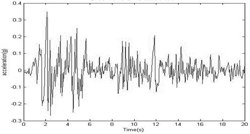
Table 3Results of numerical evaluation
Displacement (m) | Drift (m) | Acceleration (m/s2) | |||||||
Story | 1 | 2 | 3 | 1 | 2 | 3 | 1 | 2 | 3 |
POFF | 0.067 | 0.121 | 0.151 | 0.067 | 0.055 | 0.032 | 7.347 | 10.029 | 12.838 |
FLC | 0.022 | 0.038 | 0.042 | 0.022 | 0.017 | 0.014 | 5.088 | 7.343 | 7.634 |
Fitness values | |||||||||
0.296 | 0.341 | 0.658 | |||||||
PON | 0.024 | 0.039 | 0.047 | 0.027 | 0.018 | 0.016 | 4.983 | 7.453 | 7.925 |
Fitness values | |||||||||
0.318 | 0.388 | 0.670 | |||||||
Results demonstrate that damper and sensor placement can significantly improve the performance of a controlled structure. To the author’s best knowledge, there is no published research on optimal semi active control of low-rise or high-rise buildings with MR dampers by using separately sensor installation to manage the control forces more efficient. Fuzzy logic controller was considered in each floor, which the sensor was located. Regarding to the displacement and the velocity of the floor, fuzzy controller calculates the magnetic field induced current, which should be sent to each damper. PSO particles include the number and the placement of the dampers and their sensors, independently. The fitness of the population gradually improves with respect to J1, J2 and J3, with next algorithm generations. To improve the probability of finding the global optimal solution in heuristic optimization, five independent PSO algorithms were began simultaneously. Global best and local best parameters were shared in each 50 iterations. To demonstrate the efficiency of the PSO-FLC, a previously studied example was considered [35]. Two different cases are presented, in which the MR damper is utilized in a passive mode to investigate the behaviors of control structural system in semi-active and passive cases. The first passive case is denoted by ‘POFF’, in which the inducing current to the MR damper is retained at 0A and the second passive case is indicated by ‘PON’, in which the inducing current to the MR damper is kept at the maximum current (3.0 A). A previously studied clipped-optimal controller is compared to illustrate the efficiency of PSO-FLC more precisely. The simulation results for these cases are presented in Table 4.
Results demonstrate that proposed PSO-FLC reached to an advisable level of performance. The POFF controller attenuates the maximum displacement of the third story by 43 % of the uncontrolled values, the PON controller exhibits a 54 % attenuation, the clipped-optimal controller demonstrates a 46 % attenuation and the PSO-FLC decreases the responses up to 53 %. Nevertheless, the maximum control force should be taken into account to demonstrate the efficiency of a controller. Although the PON controller decreases the maximum displacement of the third story by 54 %, selecting a passive mode that employs the largest damping control forces may not be the most appropriated strategy to safeguard structural system. The PSO-FLC consumes 7 % less control forces in comparison with PON on Elcentro earthquake. Table.4 exhibits that PSO-FLC can significantly enhance the performance of the structural system.
Table 4Peak results of 3-story structural system [35] due to Elcentro earthquake
Responses | Uncontrolled structural system | Controlled structural system | |||
P-OFF | P-ON | Clipped-optimal controller | PSO-FLC | ||
1st story displacement (cm) | 0.34 | 0.16 | 0.11 | 0.12 | 0.11 |
3rd story displacement (cm) | 0.76 | 0.43 | 0.35 | 0.41 | 0.38 |
Control forces (KN) | 0 | 2.965 | 4.262 | 4.165 | 3.984 |
7.2. Case studies
Two different four and eight story shear-buildings have been considered to demonstrate the efficiency of the proposed controller. The control system and the behavior of buildings were considered linear during excitation. The excitation is the first 20 s of the N-S component of El-Centro earthquake with the peak acceleration of 0.31 g. The first structure is a four-story shear building with the following characteristics:
It is obvious that more dampers leads to more reduction in the structural response but the economical parameters should be considered to determine the number of dampers. In addition to , and , a penalty function method should be used to obtain the optimal number of dampers. For the four-story shear building, the following penalty function () is used:
where is the number of dampers, , and are three objective values, which were defined in section 7.1. By using 100 initial particles, after nine iterations algorithm reaches to the optimum solution. The optimum solution for this four-story building is:
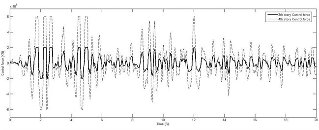
where is the damper placement vector and is the sensor placement vector. In four story shear-buildings, four 200 kN MR dampers should be used, one in the third story and three in the fourth story of structure. Only one sensor should be implemented in the fourth story. It means that one sensor is adequate for this structure. Dynamic analysis results of four-story building are shown in Table 5. Fig. 5 shows the time history of the displacement and drift responses. Fig. 6 shows the applied control forces in the third and the fourth story of building.
The placement of damper in three and four story buildings demonstrate that in low-rise buildings, the dampers and the sensors on the upper stories should be concentrated to result in more appropriated responses.
The second structure is an eight-story shear building with the following characteristics:
Table 5Four-story building numerical evaluation results
Story | 1 | 2 | 3 | 4 | |
Number of dampers | 1 | 3 | |||
Control force average | 59.97 KN | 181.16 KN | |||
Displacement (m) | Uncontrolled | 0.029 | 0.057 | 0.075 | 0.085 |
Controlled | 0.012 | 0.022 | 0.027 | 0.032 | |
Reduction Percentage | 59.9 | 61.9 | 64.1 | 62.7 | |
Drift (m) | Uncontrolled | 0.029 | 0.028 | 0.019 | 0.011 |
Controlled | 0.012 | 0.010 | 0.009 | 0.006 | |
Reduction Percentage | 59.9 | 63.9 | 52.4 | 48.7 | |
Acceleration (m/s2) | Uncontrolled | 8.270 | 12.230 | 13.190 | 16.150 |
Controlled | 5.344 | 6.029 | 6.519 | 11.069 | |
Reduction Percentage | 35.4 | 51.1 | 50.6 | 31.5 | |
Fig. 5Four-story time history of the displacement and drift responses of four-story building
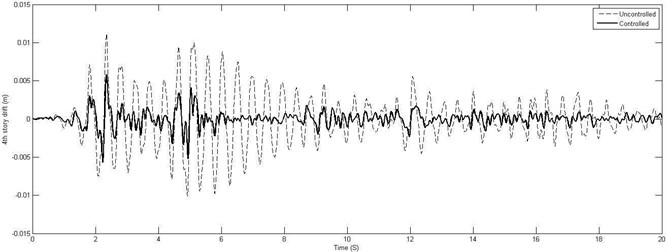
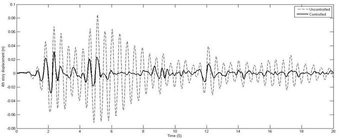
Fig. 6Applied control force in the third and the fourth story of four-story building
For the eight-story shear building the following penalty function () is used:
where is the number of dampers, , and are three objective functions, which were defined in section 7.1. Proposed PSO determines the number and the placement of the sensors and dampers by utilizing four objective functions PF, , and . The proposed algorithm uses 60 initial particles and after eleven iteration reaches to the optimum solution and in the next generation, the optimum solution remains constant. The optimum solution for this eight-story building is:
where is the damper placement vector and is the sensor placement vector. It means that the optimum number of dampers is nine. Two-200 kN MR damper should be installed in the second story, one in the third story, two in the fourth story, two in the fifth story and two in the seventh story of structure. Their sensors should be installed in the first, eighth, third, sixth and eighth story, respectively. It can be seen four sensors are adequate for this structure. Fig. 7. shows the time history of the displacement, the velocity and acceleration responses. Fig. 8 shows the third, fifth and seventh story control forces.
Fig. 7Eighth-story time history of the displacement, the velocity and the acceleration responses of eight-story building
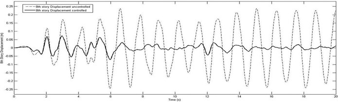
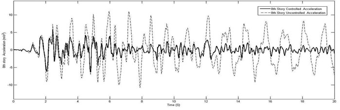
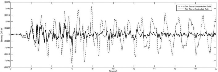
It can be seen that proposed FLC and optimum arrangement of actuators and sensors attenuated the excessive drift, displacement and acceleration responses of structure to the acceptable magnitudes. Fig. 9 shows the comparison of the maximum floor displacement in controlled and uncontrolled cases of eight-story building. In order to demonstrate the robustness and effectiveness of the proposed method, the average reduction ratios (controlled to uncontrolled displacement, drift and acceleration ratio) for the El-Centro earthquakes in all of stories in eight-story building are compared in Table 6.
Fig. 8Applied control force in the third, fifth and seventh story of eight-story building
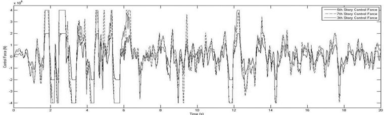
Fig. 9Comparison of the maximum floor displacement in controlled and uncontrolled cases
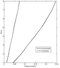
Table 6Numerical evaluation results of eight-story building
Story | 1 | 2 | 3 | 4 | 5 | 6 | 7 | 8 | |
Number of dampers | – | 2 | 1 | 2 | 2 | – | 2 | – | |
Control force average (kN) | 129.9 | 66.7 | 129.9 | 134.3 | 135.1 | ||||
Displacement (m) | Uncontrolled | 0.042 | 0.082 | 0.112 | 0.146 | 0.178 | 0.204 | 0.228 | 0.246 |
Controlled | 0.011 | 0.021 | 0.029 | 0.039 | 0.047 | 0.056 | 0.066 | 0.073 | |
Reduction Percentage | 73.0 | 73.8 | 73.8 | 73.0 | 73.7 | 72.4 | 71.2 | 70.4 | |
Drift (m) | Uncontrolled | 0.042 | 0.039 | 0.034 | 0.039 | 0.039 | 0.035 | 0.038 | 0.022 |
Controlled | 0.011 | 0.011 | 0.011 | 0.014 | 0.012 | 0.011 | 0.013 | 0.009 | |
Reduction Percentage | 73.0 | 73.0 | 68.8 | 64.4 | 68.5 | 68.5 | 67.0 | 59.5 | |
Acceleration (m/s2) | Uncontrolled | 5.022 | 6.512 | 7.968 | 9.184 | 7.734 | 7.388 | 10.070 | 11.050 |
Controlled | 4.888 | 5.741 | 5.177 | 4.807 | 4.741 | 5.698 | 5.195 | 6.317 | |
Reduction Percentage | 2.7 | 11.9 | 35.0 | 47.7 | 38.7 | 22.9 | 48.4 | 42.8 | |
Results demonstrate that proposed optimal particle swarm optimization-fuzzy logic controller (PSO-FLC) could find the optimum solution and control force. Simultaneously, PSO-FLC can optimize the number and arrangement of dampers in structural system. In 8-story shear building, PSO-FLC is capable of reducing the maximum displacement, drifts and acceleration of building to about 72.7, 67.8 and 31.3 percent of uncontrolled average responses, respectively. Thus, PSO-FLC is very effective based on the result and numerical efforts. Furthermore, the adaptability in the design of the proposed PSO-FLC to account for the variation in the excitation content in time via FLC controller makes it more robust and effective controller for seismic vibration control of structural systems.
8. Conclusions
A new modified PSO was employed to optimize the MR damper and sensor placement for the reduction of building responses subjected to a near-fault forward-directivity El-Centro time-history. An effective FLC is presented to manage inducing input current of the installed MR dampers in structural systems. Numerical efforts were undertaken to investigate the effectiveness of particle swarm optimization-fuzzy logic controller (PSO-FLCC). The results of numerical evaluation show significant performance with respect to , , and . The optimum number and the location of controllers were obtained with the least effort and in a short time. The results indicate that modified PSO algorithm is a feasible technique for determining the optimal number and the location of MR dampers. In low-rise buildings, the results demonstrate that concentrating the dampers and the sensors on the upper stories will lead to appropriated responses. Furthermore, numerical evaluations show that the location of dampers should be distributed all over the building to mitigate the responses, in high-rise buildings. The adaptability in the design of the proposed PSO-FLC to account for the variation in the excitation content in time via FLC controller makes it more robust and effective controller for seismic vibration control of structural systems.
References
-
Spencer Jr. B. F., Sain M. K. Controlling building: a new frontier in feedback control. IEEE Control System Magazine, Vol. 17, Issue 6, 1997, p. 19-35.
-
Datta T. K. Control of dynamic response of structures. Proceedings of The Indo-US Symposium on Emerging Trends in Vibration and Noise Engineering, 1996, p. 18-20.
-
Housner G. W., et al. Structural control: past, present, and future. Journal of Engineering Mechanics, Vol. 123, Issue 9, 1997, p. 897-971.
-
Rabinow J. The magnetic fluid clutch. Transactions of the American Institute of Electrical Engineers, Vol. 1948, 67, p. 1308-1315.
-
Rabinow J. Magnetic Fluid Torque and Force Transmitting Device. US Patent 2, 1951.
-
Carlson J. D., Spencer Jr B. F. Magneto-rheological fluid dampers, scalability and design issues for application to dynamic hazard mitigation. Proceedings of the 2nd International Workshop on Structural Control, Hong Kong, 1996, p. 99-109.
-
Spencer Jr B. F., Carlson J. D., Sain M. K., Yang G. On the current status of magnetorheological dampers: seismic protection of full-scale structures. Proceedings of the American Control Conference, 1997, p. 458-62.
-
Fujitani H., et al. Dynamic performance evaluation of magneto-rheological damper by experimental and analytical methods. Proceedings of the US-Japan Workshop on Smart Structures for Improved Seismic Performance in Urban Regions, Seattle, Washington, 2001, p. 237-248.
-
Sodeyama H., et al. Development of large capacity semi-active vibration control device using magnetorheological fluid. Seismic Engineering, Vol. 428, Issue 2, 2001, p. 109-114.
-
Sodeyama H., et al. A basic study on dynamic characteristics of MR dampers. Seismic Engineering, Vol. 428, Issue 2, 2001, p. 115-120.
-
Spencer B. F., et al. Phenomenological model for magnetorheological dampers. Journal of Engineering Mechanics, Vol. 3, 1997, p. 230-238.
-
Symans M. D., et al. Energy dissipation systems for seismic applications: Current practice and recent developments. Journal of Structural Engineering, Vol. 134, Issue 1, 2008, p. 3-21.
-
Takewaki I. Optimal damper placement for critical excitation. Probabilistic Engineering Mechanics, Vol. 15, 2000, p. 317-325.
-
Kennedy J., Eberhart R. C. Particle swarm optimization. Proceedings of the IEEE International Conference on Neural Networks, 1995, p. 1942-1948.
-
Shi And Eberhart Y. R. C. A modified swarm optimizer. IEEE International Conference of Evolutionary Computation, Anchorage (AK), 1998, p. 69-74.
-
Kennedy J., et al. Swarm Intelligence. San Francisco, Morgan Kaufmann, 2001.
-
Kennedy J., et al. A discrete binary version of the particle swarm algorithm. Proceedings of the IEEE Conference on Systems, Man, and Cybernetics, Piscataway, New Jersey, 1997, p. 4104-4109.
-
Yang J. N. Application of optimal control theory to civil engineering structures. Journal of Engineering Mechanics, Vol. 101, Issue 6, 1975, p. 818-38.
-
Yang J. N., Akbarpour A., Ghaemmaghami P. New optimal control algorithms for structural control. Journal of Engineering Mechanics, Vol. 113, Issue 9, 1987, p. 1369-86.
-
Yasutoshi Nomura An integrated fuzzy control system for structural vibration. Computer-Aided Civil and Infrastructure Engineering, Vol. 22, 2007, p. 306-316.
-
Zadeh L. A. Fuzzy sets. Information and Control, Vol. 8, 1965, p. 338-353.
-
Rumelhart D. E., et al. Learning representations by back-propagating errors. Nature, Vol. 323, Issue 9, 1986, p. 533-6.
-
Amini F., Zabihi Samani Masoud. A wavelet-based adaptive pole assignment method for structural control. Computer-Aided Civil and Infrastructure Engineering, Vol. 29, Issue 6, 2014, p. 464-477.
-
Zabihi Samani Masoud, Amini Fereidoun A cuckoo search controller for seismic control of a benchmark tall building. Journal of Vibroengineering, Vol. 17, Issue 3, 2015, p. 1382-1400.
-
Aghajanian S., Baghi H., Amini F., et al. Optimal control of steel structures by improved particle swarm. International Journal of Steel Structures, Vol. 14, Issue 2, 2014, p. 223-230.
-
M. Ostadali Makhmalbaf, Tutunchian M. A., Zabihi Samani Masoud Optimized fuzzy logic controller for semi-active control of buildings using particle swarm optimization. Advanced Materials Research, Vols. 255-260, 2011, p. 2505-2509.
-
Wilson C. M. D., Abdullah M. Fuzzy control of magnetorheological dampers in civil structures. Sixth European Conference on Structural Dynamics, EURODYN, Paris, France, 2005.
-
Carlson J. D., Spencer Jr B. F. Magneto-rheological fluid dampers for semi-active seismic control. Proceedings of 3rd International Conference on Motion and Vibration Control, Vol. 3, 1996, p. 35-40.
-
Spencer Jr B. F. Large-scale MR fluid dampers: modeling and dynamic performance considerations. Engineering Structures, Vol. 24, 2002, p. 309-323.
-
Yang G., et al. Dynamic model of full-scale MR dampers for civil engineering applications. US-Japan Workshop on Smart Structures for Improved Seismic Performance in Urban Region, Seattle, 2001.
-
Carrion J. E., Spencer Jr B. F. Model-Based Strategies for Real-Time Hybrid Testing. NSEL Report Series, Report No. NSEL-006, Department of Civil and Environmental Engineering, University of Illinois at Urbana-Champaign, 2007.
-
ÇETİN Ş., et al. Semi-active H∞ robust control of six degree of freedom structural system using MR damper. Turkish Journal of Electrical Engineering and Computer Sciences, Vol. 19, Issue 5, 2011, p. 797-805.
-
Tusset A., et al. On suppression of chaotic motions of a portal frame structure under non-ideal loading using a magneto-rheological damper. Journal of Theoretical and Applied Mechanics, Vol. 53, Issues 3-653, 2015, p. 2015-664.
-
MATLAB. Version 7.8.0.347, The Mathworks Inc., 2009.
-
Xiaomin Xue, et al. Semi-active control strategy using genetic algorithm for seismically excited structure combined with MR damper. Journal of Intelligent Material Systems and Structures, Vol. 22, 2011, p. 291-302.
Cited by
About this article

