Abstract
In order to extend the service life of the long-chain gear transmission system of a drum shearer, an electro-mechanical coupling model of a drum shearer cutting unit is established. The model considers the dynamic characteristics of the motor, time-varying meshing stiffness, as well as the drum load characteristics. Additionally, the dynamic characteristics and control strategy for suppressing the dynamic load of the gear transmission system under impact load are investigated based on this model. Firstly, the influence of the gear transmission system of the drum shearer cutting unit under impact load is analyzed. Then, on that basis, the active control strategy based on motor torque compensation is proposed to suppress the dynamic load of the gear transmission system caused by mutational external load. Finally, the suppression effect on the dynamic load of the gear transmission system is analyzed. Research results indicate that this control strategy has good control effects to suppress the dynamic load caused by a mutational external load, which confirms the effectiveness of the proposed control strategy.
1. Introduction
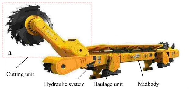
Long-wall mining is a special mining method that has high coal productivity and smooth operation. The drum shearer serves as the commonly used component in long-wall mining equipment, which is made up of the mid-body, haulage unit, hydraulic system and cutting unit as shown in Fig. 1 [1, 2]. Additionally, the drum shearer is known as the most important component in long-wall mines owing to its direct role in the cutting of coal and the production process. Meanwhile, the drum shearer cutting unit is an electro-mechanical coupling system composed of a cutting motor, gear transmission system and cutting drum, which consumes 80 %-90 % of the entire installed power of drum shearer [3], as shown in Fig. 1(a). However, a coal seam is usually non-homogenous with hard inclusion and rock intercalation, which causes the following concerns, including heavy loads, strong impacts, and large fluctuations to the drum. Thus, the cutting unit is one of the weakest parts of the drum shearer [4].
Substantial research has been conducted into the torsional vibration characteristics caused by mutational external loads within electro-mechanical coupling systems such as wind driven generators, automobiles and rolling mills. The following discussion describes the research that has been conducted into the systems that are mentioned. The dynamic torsional load of the gear train in a wind driven generator is typically caused by random wind speed; moreover, torsional vibration is one of the main reasons that lead to fatigue damage of transmission system of wind driven generators [5]. In order to reduce fatigue load of the drive-train of a wind driven generator from the perspective of the control system, a speed-based damping controller is designed to mitigate torsional oscillations in the drive-train system of a double fed induction generator (DFIG) by considering the phase lag within the torque-speed loop. The effectiveness and robustness of the damping controller with respect to various operating points are verified through damping torque coefficient analysis as well as root locus and time-domain simulations [6]. Mandic et al. [7] proposed a method that can extend the life and reliability of wind turbine gearboxes by reducing the mechanical stress on gearbox components. The reduction of mechanical stress was achieved by the generator torque control that minimizes resonant torsional vibrations within a drive-train caused by variations in wind velocity. Girsang et al. [8] proposed a novel controller for power converters to manipulate the eigenfrequency of the wind turbine drivetrain by introducing additional virtual inertia in the compensating torque. The virtual inertia controller (VIC) shifts the eigenfrequency of the system only when the drive-train passes through its inherent resonance. Rapid acceleration or deceleration as well as changing road conditions may lead to torsional vibration of an automobile transmission system, which not only has an important effect on fatigue damage of the gear transmission system, but also influences the comfort of the ride [9]. A motor control scheme consisting of a linear quadratic regulator (LQR) and state observer was proposed by Fu et al. [10] for a motor-transmission integrated drive system of an electric vehicle to suppress the torsional vibration of the system. Amann et al. [11] and Fazal et al. [12] designed an active damping wheel-torque control system to suppress oscillations to improve the drivability of a power-split hybrid electric vehicle (HEV). Their approach used the wheel speed and motor speed as the feedback signals to compensate the desired generator torque by controlling the motor to suppress torsional vibration of the HEV powertrain. Transient torsional vibrations of the powertrain of a rolling mill may be induced by impact loads that can occur during the course of biting and throwing steel. The peak torque caused by torsional vibration leads to high alternating stress of the shafting which then results in partial fatigue failure of the shaft components [13]. The dynamics equations of the main drive system of a two-mass rolling mill with nonlinear damping and nonlinear stiffness were established under the action of impact moment by Liu et al. [14]. The torsional vibration responses of system were obtained, and the influences of the nonlinear damping and nonlinear stiffness of shafting on vibration responses of the rolling mill’s drive system were discussed. Additionally, a new control concept was proposed by Zhang et al. [15] for the drive system of a rolling mill to achieve vibration suppression and disturbance rejection based on extended state observer (ESO) and linear quadratic (LQ) controllers. Its validity and superiority was verified in comparison with a conventional PI controller.
Fig. 1Drum shearer
The research discussed above is aimed at electro-mechanical coupling powertrains that are applied in different areas where the dynamic characteristics of electro-mechanical coupling powertrain under impact loads and the control methods of suppressing dynamic load have been investigated. The previous research suggests that dynamic torsional load of an electro-mechanical coupling powertrain is induced by mutational external load, which can then lead to fatigue failure of the transmission system. Because of the harsh working conditions in longwall mining, the mutational external load is transmitted to the gear transmission system by the cutting drum thereby causing damage to the gears in the transmission system. Therefore, the performance of the drum shearer cutting unit has been receiving more and more attention by scholars to improve the service performance. However, the studies are mainly centralized in the area of reliability optimization design of the transmission system, pick alignment optimization of shearer cutting drum and innovative design of transmission system itself [2-4, 16-19]. Nevertheless, related research on the influence of the dynamic load characteristics of the gear transmission system of the drum shearer under impact loads and the control strategy to suppress the dynamic load of the gear transmission system is rarely reported. As a consequence, in order to adjust to the complex and changing cutting condition and extend the service life of the gear transmission system of the drum shearer, it is essential to study the influence law of the dynamic load of the gear transmission system under impact loads as well as the control strategy for suppressing dynamic load by controlling the cutting motor. This could lay a foundation for adaptive control of the gear transmission system of a drum shearer.
In this paper, an electro-mechanical coupling model of the drum shearer cutting unit is established including a motor model, a dynamic model of gear transmission system, and a drum load model. Then, the influence of the dynamic load of a gear transmission system of the drum shearer cutting unit under impact loads is analyzed. From there, a control strategy is proposed aimed at suppressing the dynamic load of the gear transmission system on the basis of the influence law. Finally, the suppression effect on the dynamic load of the gear transmission system under impact loads is studied.
2. The electro-mechanical coupling model of the drum shearer cutting unit
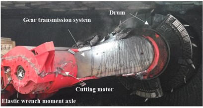
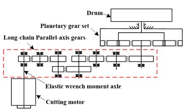
Fig. 2 shows the drum shearer cutting unit that includes the cutting motor, gear transmission system as well as the cutting drum. The gear transmission system is a long-chain with a series of parallel-axis gears and a stage of planetary gear set. Additionally, the elastic wrench moment axle connects the cutting motor with gear transmission system and also serves as an elastic buffer device for the transmission system.
2.1. Mathematical modeling of an induction motor
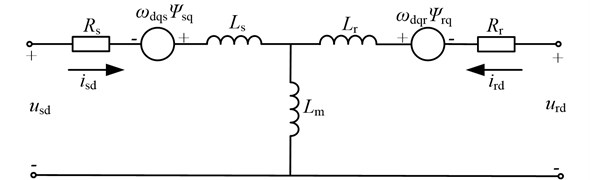
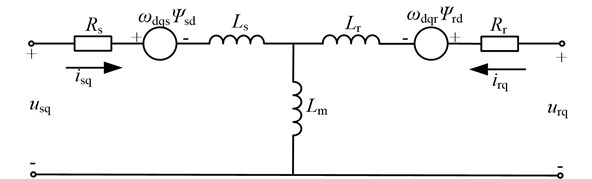
The asynchronous motor, which is a high-order, nonlinear and strong-coupling system of multi-variables, is widely adopted for the drum shearer cutting unit. In order to minimize the number of equations, the state space equations for the dynamic model of the asynchronous motor are usually obtained in the - coordinate frame. The equivalent circuit of the asynchronous motor in the - coordinate frame is shown in Fig. 3.
The mathematical equations for the asynchronous motor are derived as follows [20, 21]:
Flux-linkage equations:
The mechanical equation can be written as:
where ; , denote the stator voltage component, respectively; denotes the electromagnetic torque; denotes the load torque; denotes the motor inertia; denotes the friction coefficient; denotes the number of motor pole pairs; denotes the angular displacement of rotor; , denote the stator resistance and rotor resistance, respectively; , and denote the stator, rotor and mutual inductances, respectively; , denote the d-axis stator and rotor current, respectively; denote the -axis stator and rotor current, respectively.
Fig. 2Drum shearer cutting unit: a) factual picture, b) structure diagram
a)
b)
Fig. 3The equivalent circuit of an asynchronous motor in the d-q coordinate frame
a)-axis
b)-axis
2.2. Dynamic modeling of the gear transmission system
As the rotating speed of the electric motor is variable owing to load fluctuations, a dynamic model of the variable speed process for the gear transmission system is needed to conduct the electromechanical dynamic analysis of the drum driving system. The dynamic model of the gear transmission system is established by the lumped mass method including the multistage parallel shaft gears and the planetary gear set. Moreover, the angular displacements are chosen as the generalized coordinates for the dynamic model of the gear transmission system, thereby it is realizable to connect the motor and gear transmission system [4, 22]. As the modeling method of the parallel shaft gears is similar to the planetary gear system, this paper uses the modeling process of a planetary gear set as an example. Fig. 4 shows the dynamic model of the planetary gear set.
In Fig. 4, three types of coordinate systems are constructed: (1) the static coordinate system ; (2) the moving coordinate system oxy rotating with carrier; (3) the moving coordinate system ( 1,…, and is the number of planets) rotating with the carrier, where -axis is in the radial direction and -axis is in the tangential direction. The angular displacements (, ) are assigned to the sun and ring, respectively, which are measured in the moving coordinate system . The symbol denotes the angular displacement of the carrier that is measured in the static system . The symbol denotes the angular displacement of the nth planet that is measured in the moving coordinate system . are chosen as the generalized coordinates to construct the dynamic model of planetary gear set. The symbol denotes the position angle of the theoretical center of the th planet, where . The symbols and denote the torque acting on the sun and carrier, respectively. The symbol denotes the torque acting on the ring gear that is provided by the gearbox house, where . The symbol denotes the torsional supporting stiffness of the ring that is provided by the gearbox house as the ring is usually fixed to the gearbox house.
Fig. 4The dynamic model of the planetary gear set
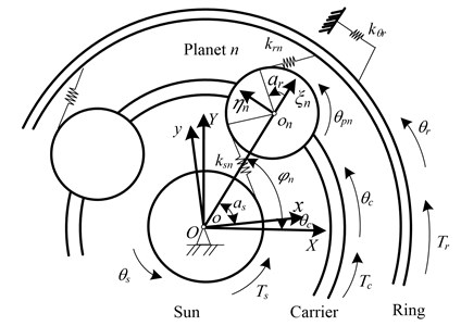
Fig. 5Transformation to parallel-axis gear pairs: a) from the sun–planet gear pair to a parallel-axis external gear pair and b) from the planet–ring gear pair to a parallel-axis internal gear pair
a)
b)
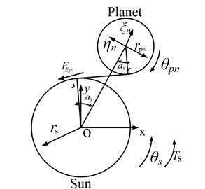
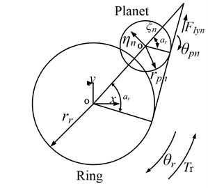
In the moving coordinate system, the planetary gear set can be transformed to parallel-axis external gear pairs (sun-planet) and internal gear pairs (planet-ring), as shown in Fig. 5.
As a result, the dynamical equations of the external gear pairs and internal gear pairs after transformation are as follows:
where , , denote radius of base circle of sun, planets, ring, respectively. , denote meshing stiffness and damping between sun and planets, respectively; , denote meshing stiffness and damping between planets and ring, respectively. The gear time-varying stiffness and can be calculated according to [22]. Upon obtaining the meshing forces of the external gear pairs and internal gear pairs, Newton’s law for a non-inertial coordinate system is utilized to obtain the equations of motion of the planetary gears, as shown in Eq. (5):
2.3. Modeling of the drum load
The drum load main considers the tangential cutting resistance, which depends on the working principle of the drum picks. The equation of the drum load is as follows:
where denotes the number of picks that cut the coal seam; denotes the drum diameter; denotes the mean cutting tangential force of each pick where can be calculated based on the follow equation:
where denotes the mean cutting resistance that depend on the physical properties of the coal seam; denotes the cutting width of picks; , , , , , denote the correlation coefficient of pick or coal seam, respectively; denotes the width of picks; denotes the deflection angle of picks relative to the advancing direction of drum shearer; denotes the mean cutting thickness of the picks where can be calculated based on the follow equation:
where denotes the surrounding angle of drum relative to the coal seam; denotes the haulage speed of the drum shearer; denotes the cutting speed of drum; denotes the number of picks that laid in one transversal of drum.
2.4. Electro-mechanical coupling modeling of the drum shearer cutting unit
Fig. 6 shows the electro-mechanical coupling model of the drum shearer cutting unit. denotes the rotational inertia of drum; denotes the drum load torque; denotes the angular displacement of drum, and denote equivalent stiffness and damping of the elastic wrench moment axle, respectively; and denote the equivalent stiffness and damping of the different gear shafts, 1, 2; and and denote equivalent stiffness and damping between the planetary gear set and drum, respectively. The electro-mechanical coupling model of the drum shearer cutting unit can be constructed based on the motor model, the gear transmission system model as well as the drum load model. The mathematical model is as shown in Eq. (9):
where denotes the dynamic meshing force between two meshing gears, ( 1, 2,…8; 2, 3…9); and denote rotational inertia of sun, carrier and multistage parallel shaft gears, respectively; and denote rotational inertia and radius of multistage parallel shaft gears, 1, 2,...9; denote the angular displacement of multistage parallel shaft gears.
Fig. 6Electro-mechanical coupling model of drum shearer cutting unit
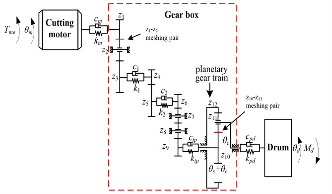
Table 1Parameters of the drum shearer cutting unit
Main parameters | |||||||||||||
Electric motor | Rated power 300 kW; Synchronous speed 1500 r/min; Rated speed 1480 r/min; Rated voltage1140 V; 10 Kg·m2; Pole pairs 2; 0.0687 Ω; 0.0743 Ω; 0.0266H; 1.41831H; 1.41831023H; the electric motor is connected in | ||||||||||||
Drum | 2000 Kg·m2; 2000 mm; 1.25; 0.9. | ||||||||||||
Gear system | No. | ||||||||||||
Teeth | 21 | 38 | 39 | 23 | 44 | 21 | 38 | 38 | 47 | 16 | 24 | 64 | |
Stiffness and damping | 5×10⁴N·m-1, 8 N·m·s·rad-1; 2×10⁷N·m-1, 140 N·m·s·rad-1; 4.6×10⁷N·m-1, 350 N·m·s·rad-1; 5.7×10⁶N·m-1, 75 N·m·s·rad-1; 1×10⁹N·m-1, 1.4×10⁴N·m·s·rad-1 | ||||||||||||
Inertia | 0.03 Kg·m2, 0.3263 Kg·m2; 0.3623 Kg·m2; J4= 0.0493 Kg·m2; 1.1243 Kg·m2; 0.1283 Kg·m2; 1.3723 Kg·m2; 1.3723 Kg·m2; 3.2123 Kg·m2; 0.0453 Kg·m2; 0.2253 Kg·m2; 9.6013 Kg·m2; 9.2373 Kg·m2 | ||||||||||||
3. Dynamic load characteristics of the gear transmission system of a drum shearer under impact loads
3.1. Effect of impact loads on the dynamic characteristics of the gear transmission system
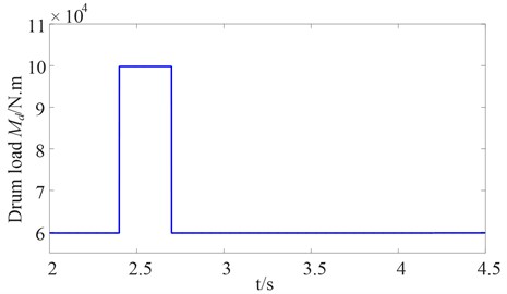
A coal seam is usually in non-homogenous with hard inclusion and rock intercalation, which induces heavy loads, strong impacts, and large fluctuations to the shear drum load. When the shearer encounters a normal coal seam, the fluctuation of the cutting force is small, the cutting force can be simulated by a constant force. When the shearer encounters a coal seam with hard inclusion and rock intercalation, the cutting force can be simulated by a pulse force [4]. The sudden change in the drum load can occur quickly, which is an obvious and dangerous characteristic of the drum load. In order to analyze the effect of an impact load on the gear transmission system of drum shearer, the pulse load is directly supplied to the drum, as shown in Fig. 7. The drum load under steady load is 60000 Nm, it then increases suddenly from 60000 Nm to 100000 Nm where the simulation time is 2.4 s and lasts for 0.3 s. The impact load is approximately 1.67 times as much as the steady load. The parameters of the drum shearer cutting unit are shown in Table 1.
Fig. 7Torque acting on the drum
As the first stage parallel shaft gears of the high-speed side and the planetary gear of the low-speed side in the gear transmission system of drum shearer are the specific parts with the highest failure rate [22, 23], this paper mainly analyzes the dynamic meshing force between the first stage gear and the idler gear at the high-speed side, as well as the dynamic meshing force between the sun gear and planet gear at the low-speed side.
Fig. 8 shows the curves for the dynamic meshing force between the first stage gear and the idler gear at the high-speed side. The maximum value of the dynamic meshing force of the -meshing pairs under steady load (before 2.4 s) is 3.81×10⁴ N. It is noteworthy that the oscillation phenomenon of dynamic meshing force of the -meshing pairs is caused instantaneously when the drum load increases suddenly. The maximum value of the dynamic meshing force is 8.24×10⁴ N, which is approximately 2.16 times the steady load, subsequently, the oscillation amplitude diminishes slowly. Additionally, the oscillation phenomenon of the dynamic meshing force of the - meshing pairs is also caused when the drum load suddenly decreases. In this case, the maximum value of the dynamic meshing force is 5.61×10⁴ N, which is approximately 1.47 times the steady load, and then the oscillation amplitude gradually diminishes. Because of the complex and changing cutting conditions, the repeated impact loads may lead to fatigue damage of the gear transmission system. This transient process caused by the impact loads receives significant attention in this study.
Fig. 9 shows the curves for the dynamic meshing force between the sun gear and planet gear at the low-speed side. However, the trend of the dynamic meshing force between the sun gear and planet gear at the low-speed side when under impact is similar to the dynamic meshing force between the first stage gear and idler gear at the high-speed side and need not be repeated here.
Fig. 8Dynamic meshing force between the first stage gear and idler gear at the high-speed side
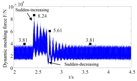
Fig. 9Dynamic meshing force between the sun gear and planet gear at the low-speed side
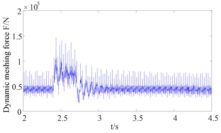
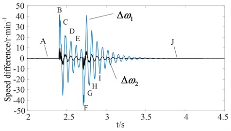
Fig. 10 shows the curve for the elastic wrench moment axle load while Fig. 11 shows the curves for the speed difference between the rotor and the first stage gear at the high-speed side. The speed difference between the first stage gear and the drum speed equivalent to the high-speed side, where, 30(-, 30(- ( denotes the total ratio of the gear transmission system). When the external load is steady, the elastic wrench moment axle load is steady at 1600 N·m and speed difference is zero under the steady load (before 2.4 s), as shown in Figs. 10 and 11 as data point A. However, the torsional vibration of the elastic wrench moment axle is induced by the pulse load, and then the torsional vibration amplitude diminishes slowly. In addition, the speed difference is also caused by the pulse load, and then the speed difference amplitude diminishes slowly and tends to zero. Therefore, an offset trend from point B to point E can be obtained, which is basically identical with the offset trend from point B to point E of the elastic axle load. Additionally, the offset trend from point F to point I of the speed difference is similar to the offset trend from point F to point I of the elastic axle load. Moreover, when the external load returns to a new stable state, the speed difference returns to zero again, as shown in Figs. 10 and 11 as data point J. Therefore, the speed difference is basically identical with the elastic axle load. Nevertheless, the speed difference between the rotor and the first stage gear at the high-speed side is far greater than the speed difference between the first stage gear at the high-speed side and the drum speed equivalent to the high-speed side, as shown in Fig. 11. This is because the elastic wrench moment axle has the function of power transfer, an elastic buffer as well as overload protection, which is designed with a lower stiffness. Additionally, as the rock and coal act on the drum directly, the drum speed and speed difference are much more difficult to obtain from an actual harsh environment, therefore, it is better to choose the speed difference as a feedback signal to reflect the torsional vibration characteristics of the elastic wrench moment axle and oscillation phenomenon of the dynamic meshing force of the gear transmission system.
Fig. 10Elastic wrench moment axle load
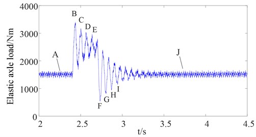
Fig. 11Speed difference
3.2. Dynamic characteristics of the gear transmission system considering the drum load characteristics
According to the drum load model from Eqs. (6)-(8), the sudden change of the cutting resistance leads to changes in the drum load. Nevertheless, when the physical parameters of a coal seam remains constant including the cutting resistance and the other physical parameters, the drum load is only dependent on the haulage speed of the drum shearer and cutting speed of the drum. The existing drum load characteristics are shown in Fig. 12 where the drum load is proportional to the haulage speed of the drum shearer and is inversely proportional to the cutting speed of the drum However, in the previous study, the impact load is directly supplied to the drum without considering the drum load characteristics, as shown in Fig. 7. Hence, it is necessary in the following analysis to study the dynamic characteristic of the gear transmission system while considering the drum load characteristics.
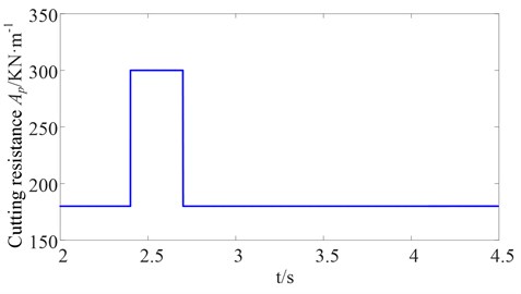
Fig. 13 shows the curve for the cutting resistance . The cutting resistance increases suddenly from 180 KN·m to 300 KN·m for a simulation time of 2.4 s and lasts for 0.3 s. The drum load is then calculated based on the drum load model and is directly supplied to the drum.
Fig. 12Characteristics surface of drum load
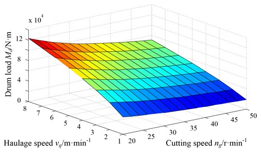
Fig. 13Cutting resistance of coal seam
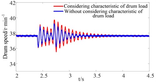
Figs. 14-15 show the curves for the dynamic meshing force between the first stage gear and idler gear at the high-speed side, and the curves for the dynamic meshing force between the sun gear and planet gear at the low-speed side, respectively. The simulation results show that the amplitude of the dynamic meshing force while considering the drum load characteristics is much greater than the case without considering the drum load characteristics. Furthermore, the elapsed time to reach steady state is much longer. This is because the sudden changes of the cutting resistance leads to sudden changes of the drum load and fluctuation of drum speed. However, according to the drum load characteristics, when the physical parameters of the coal seam and the haulage speed of the drum shearer remain constant, the drum load is only dependent on the cutting speed of the drum. The fluctuation of the drum speed, which in turn affects the drum load, is shown in Figs. 16-17. Therefore, the fluctuation of the drum load is much greater when considering the drum load characteristics, which increases the dynamic meshing force of the gear transmission system to a certain extent.
In conclusion, the fluctuation of the drum load increases the dynamic meshing force of the gear transmission system under an impact load. According to the drum load characteristics, the fluctuation of the drum load could be diminished by controlling the drum speed, thereby suppressing the dynamic meshing force of the gear transmission system to some extent.
Fig. 14Dynamic meshing force between the first stage gear and idler gear at the high-speed side
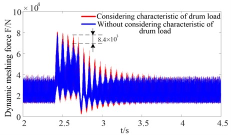
Fig. 15Dynamic meshing force between the sun gear and planet gear at the low-speed side
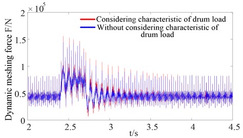
Fig. 16Drum load
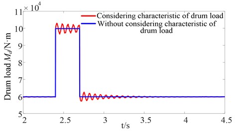
Fig. 17Drum speed
4. Active control strategy for suppressing the dynamic load of the gear transmission system based on motor torque compensation
As previous discussed above, the dynamic load characteristics of the gear transmission system of the drum shearer under an impact load are analyzed. The research results indicate that the speed difference can be used as a feedback signal to reflect the torsional vibration characteristics of the elastic wrench moment axle and oscillation phenomenon of dynamic meshing force of gear transmission system. Additionally, the fluctuation of the drum load could be diminished by controlling the drum speed, thereby suppressing the dynamic meshing force of the gear transmission system to some extent. Then, on the basis of these dynamic load characteristics of the gear transmission system, the control strategy based on motor torque compensation is proposed with an aim of suppressing the dynamic load of the transmission system. Furthermore, the suppression effect on the dynamic load of the shear cutting transmission under an impact load is analyzed.
4.1. Active control strategy for suppressing the dynamic load of the gear transmission system
4.1.1. Direct torque control model
As the cutting motor of the traditional drum shearer is an asynchronous motor without control, the cutting motor is controlled using a direct torque control (DTC) system, which has the advantages of strong robustness to parameter variations, a fast dynamic response, etc. The DTC scheme only needs two hysteresis comparators and a switching vector table for both the flux and torque control [24]. Utilizing the speed difference between the target speed and the actual speed as input variable of the PI controller, the motor target electromagnetic torque can be calculated by the PI controller in real time. The diagram of the structure and principle of the DTC as showed in Fig. 18.
Fig. 18Diagram of structure and principle of the DTC
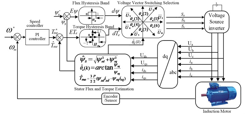
The stator flux can be estimated based on the stator voltage and stator current, which is given by:
where and .
The expressions for the estimated electromagnetic torque and angle between the stator and rotor flux are:
4.1.2. Active control strategy based on motor torque compensation
In order to suppress the dynamic load of the gear transmission system under an impact load, an active control strategy based on motor torque compensation is proposed based on several factors including the basis of the given target electromagnetic torque from the PI controller of the DTC and additional torque that is opposite of the direction of torsional vibration of the elastic wrench moment axle load. Therefore, the dynamic load of the gear transmission system can be suppressed by controlling motor electromagnetic torque. The detailed contents of the control strategy are constructed as follows: (1) using the actual motor speed as a feedback signal, generate the electromagnetic torque to decrease the fluctuation of the drum load; and (2) using the speed difference as a feedback signal, generate the electromagnetic torque to suppress the torsional vibration of the elastic wrench moment axle load. Hence, the final target electromagnetic torque is the sum of and . The equation of the final target electromagnetic torque can be written as:
where can be obtained from the PI controller of DTC, and can be obtained after performing a filtering and amplifying treatment on the speed difference of the elastic wrench moment axle based on a band-pass filter. The diagram of the active control strategy for suppressing the dynamic load of the gear transmission system is shown in Fig. 19. The main controller parameters are shown in Table 2.
Fig. 19The diagram of the active control strategy for suppressing the dynamic load of the gear transmission system
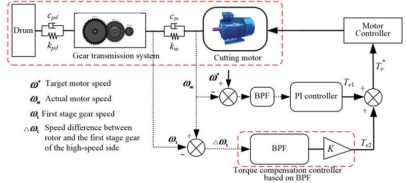
Table 2Main controller parameters
Main controller parameters | 100; 200; 1 web; 1480 r/min; Flux Hysteresis Band: 0.1web; Torque Hysteresis Band: 10 N·m; Maximum switching frequency: 20000 Hz; 40 |
4.2. Simulation results
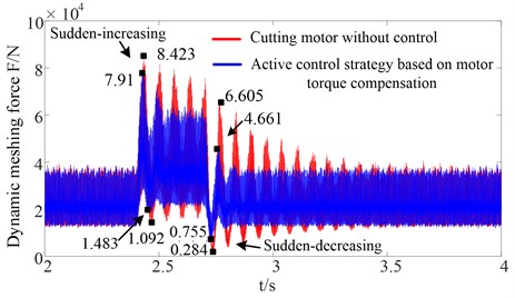
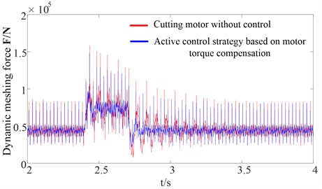
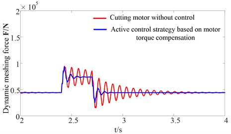
The sudden changes of the cutting resistance are the same as Fig. 13. Figs. 20-21 show the curves for the dynamic meshing force between the first stage gear and idler gear at the high-speed side, and the curves for the dynamic meshing force between the sun gear and planet gear at the low-speed side, respectively.
Fig. 20Dynamic meshing force between the first stage gear and idler gear at the high-speed side
a) Time varying mesh stiffness
b) Constant mesh stiffness
Table 3Statistic results of dynamic meshing force at the high-speed side under sudden increasing load condition
Minimum value | Maximum value | Mean value | Standard deviation | |
Motor without control | 1.092×10⁴ N | 8.423×10⁴ N | 3.663×10⁴ N | 8.177×10³ N |
The proposed control strategy | 1.483×10⁴ N | 7.91×10⁴ N | 3.642×10⁴ N | 5.083×10³ N |
Table 4Statistic results of dynamic meshing force at the high-speed side under sudden decreasing load condition
Minimum value | Maximum value | Mean value | Standard deviation | |
Motor without control | 0.284×10⁴ N | 6.605×10⁴ N | 2.167×10⁴ N | 4.677×10³ N |
The proposed control strategy | 0.755×10⁴ N | 4.661×10⁴ N | 2.169×10⁴ N | 2.430×10³ N |
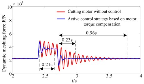
The simulation results show that the amplitude of the dynamic meshing force increases when the cutting resistance abruptly increases. Subsequently, the oscillation amplitude gradually diminishes. Compared with the traditional drum shearer whose cutting motor is not controlled, adopting the active control strategy based on motor torque compensation can rapidly suppress the dynamic load caused by a mutational external load. Furthermore, the elapsed time that is required to reach steady state is much shorter. As shown in the Fig. 20(b), the elapsed time that is required to reach steady state is 0.21 s and 0.23 s, respectively, which are much shorter than for the traditional drum shearer. Additionally, the statistic results of the dynamic meshing force based on the time varying mesh stiffness at the high-speed side under both sudden increasing load condition and sudden decreasing load condition are presented, respectively, as shown in Table 3 and Table 4. The mean values are approximately equal before and after adopting the active control strategy, however, the dynamic meshing force standard deviation of adopting the active control strategy based on motor torque compensation is reduced approximately 37.83 % and 48.04 % compared with the traditional drum shearer whose cutting motor is not controlled, respectively. This confirms the effectiveness of suppressing the dynamic load of the gear transmission system. This is because the active control strategy based on motor torque compensation using the actual motor speed as a feedback signal, and on the basis of the given torque from the PI controller of the DTC, by adding an additional torque that opposes the direction of the torsional vibration of the elastic wrench moment axle load, the fluctuation of drum load and torsional vibration of the elastic wrench moment axle could be suppressed by controlling motor electromagnetic torque, thus the dynamic load of the gear transmission system can be suppressed.
Fig. 21Dynamic meshing force between the sun gear and planet gear at the low-speed side
a) Time varying mesh stiffness
b) Constant mesh stiffness
Fig. 22Motor electromagnetic torque
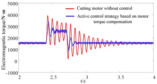
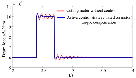
Fig. 22 shows the curves for the motor electromagnetic torque compared with the traditional drum shearer whose cutting motor is not controlled. Both the fluctuation amplitude and elapsed time required for the motor electromagnetic torque to reach steady state are decreased significantly based on the proposed active control strategy. Figs. 23-24 show the curves for the torsional vibration of the elastic wrench moment axle load and drum load, respectively. The simulation results show that the fluctuation of the drum load and torsional vibration of the elastic wrench moment axle are suppressed. Thus, the dynamic load of the gear transmission system is suppressed rapidly and effectively. The dynamic characteristics of the gear transmission system of the drum shearer when the cutting resistance decreases abruptly are similar to the dynamic characteristics of the gear transmission system of the drum shearer when the cutting resistance increases abruptly and need not be repeated here.
In conclusion, compared with the traditional drum shearer whose cutting motor is not controlled, the dynamic load of the gear transmission system caused by a mutational external load can be rapidly and effectively suppressed by adopting an active control strategy based on motor torque compensation.
Fig. 23Elastic wrench moment axle load
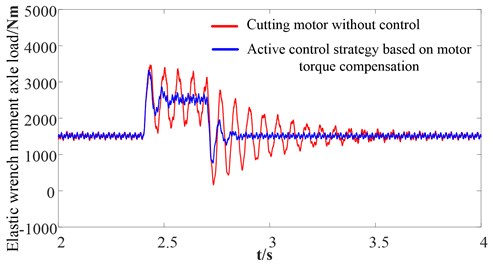
Fig. 24Drum load
5. Conclusions
In this paper, an electro-mechanical coupling model of the drum shearer cutting unit is established including the motor model, the dynamic model of the gear transmission system, as well as the drum load model. The influence law of the dynamic load of the gear transmission system of the drum shearer cutting unit under an impact load is obtained in order to extend the service life of the long-chain gear transmission system of the drum shearer cutting unit. On the basis of the influence law of the dynamic load of the gear transmission system, the active control strategy aims to suppress the dynamic load of the transmission system is proposed. Additionally, the suppression effect on the dynamic load of the gear transmission system under an impact load is analyzed. Then the main conclusions are as follows:
1) The torsional vibration of the elastic wrench moment axle load and the oscillation phenomenon of the dynamic load of the gear transmission system are caused by both sudden-increasing and sudden-decreasing drum loads. Ultimately, the repeated impact load may lead to fatigue damage of the gear transmission system and reduce the service life of the drum shearer cutting unit. The speed difference can be used as the feedback signal to reflect the torsional vibration characteristics of the elastic wrench moment axle and the oscillation phenomenon of the dynamic meshing force of the gear transmission system.
2) The fluctuation of the drum load increases the dynamic meshing force of the gear transmission system under the impact loads. According to the drum load characteristic, the fluctuation of the drum load can be diminished by controlling the drum speed. Therefore, dynamic meshing force of the gear transmission system can be suppressed to some extent.
3) Compared with the traditional drum shearer whose cutting motor is not being controlled, the dynamic load of the gear transmission system induced by the mutational external load can be rapidly and effectively suppressed by adopting the active control strategy based on motor torque compensation. This confirms the effectiveness of the proposed control strategy. This study lays a foundation for adaptive control of the gear transmission system of the drum shearer.
References
-
Seyed H. H., Mohammad A., Reza K., et al. Reliability and maintainability analysis of electrical system of drum shearers. Journal of Coal Science and Engineering, Vol. 17, Issue 2, 2011, p. 192-197.
-
Shu R., Liu Z., Liu C., et al. Load sharing characteristic analysis of short driving system in the longwall shearer. Journal of Viroengineering, Vol. 29, Issue 4, 2015, p. 3572-3585.
-
Yang Y., Zou J., Qin D., et al. High reliability electromechanical-hydraulic short-range cutting transmission system of shearer. Journal of Mechanical Engineering, Vol. 52, Issue 4, 2016, p. 111-119.
-
Liu C., Qin D., Liao Y. Electromechanical dynamic analysis for the drum driving system of the long-wall shearer. Advances in Mechanical Engineering, Vol. 7, Issue 10, 2015, p. 1-14.
-
Molinas M., Suul J. A., Undeland T. Extending the life of gear box in wind generators by smoothing transient torque with STATCOM. IEEE Transactions on Industrial Electronics, Vol. 57, Issue 2, 2010, p. 476-484.
-
Wang L., Cheng L., Sun Y., et al. Damping control of drive-train system of DFIG to compensate phase lag characteristics of electromagnetic torque-generator speed closed loop. Power System Technology, Vol. 12, 2014, p. 3333-3340.
-
Mandic G., Nasiri A., Muljadi E., et al. Active torque control for gearbox load reduction in a variable-speed wind turbine. IEEE Transactions on Industry Applications, Vol. 48, Issue 6, 2012, p. 2424-2432.
-
Girsang I. P., Dhupia J. S., Muljadi E., et al. Modeling and control to mitigate resonant load in variable-speed wind turbine drivetrain. IEEE Journal of Emerging and Selected Topics in Power Electronics, Vol. 1, Issue 4, 2013, p. 277-286.
-
Ebrahimi M., Farshidianfar A., Bartlett H. Hybrid modelling and simulation of the torsional vibration of vehicle driveline systems. Proceedings of the Institution of Mechanical Engineers Part D Journal of Automobile Engineering, Vol. 215, Issue 2, 2003, p. 217-229.
-
Hong F., Tian G., Chen H., et al. A study on the torsional vibration control of motor-transmission integrated drive system. Automotive Engineering, Vol. 7, 2010, p. 596-600.
-
Amann N., Bocker J., Prenner F. Active damping of drive train oscillations for an electrically driven vehicle. IEEE/ASME Transactions on Mechatronics, Vol. 9, Issue 4, 2005, p. 697-700.
-
Fazal Syed U., Kuang M. L., Ying H. Active damping wheel-torque control system to reduce driveline oscillations in a power-split hybrid electric vehicle. IEEE Transactions on Vehicular Technology, Vol. 58, Issue 9, 2009, p. 4769-4785.
-
Amer Y. A., El-Sayed A. T., El-Bahrawy F. T. Torsional vibration reduction for rolling mill’s main drive system via negative velocity feedback under parametric excitation. Journal of Mechanical Science and Technology, Vol. 29, Issue 4, 2015, p. 1581-1589.
-
Liu H., Zhang Y., Li X., et al. Investigation and restraining of impact torsional vibration of rolling mill’s nonlinear drive system. Journal of Vibration and Shock, Vol. 29, Issue 7, 2010, p. 179-183.
-
Zhang R., Tong C. Torsional vibration control of the main drive system of a rolling mill based on an extended state observer and linear quadratic control. Journal of Vibration and Control, Vol. 12, Issue 3, 2006, p. 313-327.
-
Song-Yong L., Chang-Long D., Xin-Xia C., et al. Experiment research on a new shearer drum. Procedia Earth and Planetary Science, Vol. 1, Issue 1, 2009, p. 1393-1397.
-
Du C. L., Liu S. Y., Cui X. X., et al. Study on pick arrangement of shearer drum based on load fluctuation. Journal of China University of Mining and Technology, Vol. 18, Issue 2, 2008, p. 305-310.
-
Zhang Y., Huang J., Zhu L., et al. Reliability-based robust optimization design of the transmission system of a shearer ranging arm. Journal of China Coal Society, Vol. 40, Issue 11, 2015, p. 2540-2545.
-
Jing W., Shu R., Qin D. Study of synchronization characteristics of a multi-source driving transmission system under an impact load. International Journal of Precision Engineering and Manufacturing, Vol. 17, Issue 9, 2016, p. 1157-1174.
-
Zaky M. S. High performance DTC of induction motor drives over a wide speed range. Electrical Engineering, Vol. 97, Issue 2, 2015, p. 139-154.
-
Ramesh T., Kumar Panda A., Shiva Kumar S. Type-2 fuzzy logic control based MRAS speed estimator for speed sensorless direct torque and flux control of an induction motor drive. ISA Transactions, Vol. 57, 2015, p. 262-275.
-
Liu C., Qin D., Lim T. C., et al. Dynamic characteristics of the herringbone planetary gear set during the variable speed process. Journal of Sound and Vibration, Vol. 333, Issue 24, 2014, p. 6498-6515.
-
Ge S., Qin D., Hu M. Research on drum shearer speed control strategies under impact conditions. Journal of China Coal Society, Vol. 40, Issue 11, 2015, p. 2569-2578.
-
Uddin M., Hafeez M. FLC-based DTC scheme to improve the dynamic performance of an IM drive. IEEE Transactions on Industry Applications, Vol. 48, Issue 2, 2012, p. 823-831.
Cited by
About this article

The authors would like to acknowledge the support and contribution from the State Key Lab of Mechanical Transmission, Chongqing University, China. This research was funded by the National Major Basic Research Program of China (973 Program, Grant No. 2014CB046304).
