Abstract
Vibration control of rotating composite blade beam with piezoelectric patch embedded is investigated. Stall flutter of piezo-composite blade driven by nonlinear aerodynamic forces is analyzed based on anisotropic circumferentially uniform stiffness (CUS) configuration. The blade is modeled as single-cell thin-walled beam structure, exhibiting the couplings among three displacements of vertical bending, lateral bending and transverse shear deformation, with structural tailoring implemented. The transversely piezoelectric actuating element is embedded in a manner such that its surface is parallel to the mid-surface of the blade beam. Piezoelectric damping ratios of rotating piezo-composite blade are described, with influences of different ply angles and rotating speeds illustrated. The flutter suppression for stall aeroelastic behavior based on an optimal LQG controller (OLC) with a dynamic regulator is highlighted with obvious effects demonstrated. In contrast with conventional LQG controller, the superiority of OLC controller is apparently demonstrated by time response and piezoelectric feedback voltage. Analytical proof of the structural modeling and feasibility analysis of the physical realization of the OLC algorithm are also investigated by comparisons of different modeling theories, and demonstrated by experimental platform.
1. Introduction
Thin-walled composite beam is widely used in the construction of rotating rotor blade. Vibration characteristics and aeroelastic control of such blade beams have become important issues which should be investigated during analysis of stall-induced flutter suppression for turbines or helicopters. For the active control of blade aeroelasticity based on actuators and load reduction, the researchers at Technical University of Denmark, Deltf University, Chinese Academy of Sciences and other academic institutions have conducted a lot of work in the last few years. Andersen et al. investigated the potential for fatigue load reduction applying trailing-edge flaps on wind turbine blade [1]. Cooperman and Martinez investigated the control requirements of load monitoring sensors, sensing technologies and applications for load control [2]. Mingming et al. presented a numerical study on the parametric effect of deformable trailing-edge flap on the fatigue load of a large-scale wind turbine blade [3]. Ng et al. presented an aeroservoelastic modeling approach to investigate dynamic load alleviation in large wind turbines with composite blades and trailing-edge aerodynamic surfaces [4]. Li et al. provided a method to develop an aeroelastic model of a smart blade section equipped with tab [5], with the effectiveness investigated by the scenarios of different output controllers and actuation deployments.
In the past ten years, a number of issues related to the nonlinear aeroelastic modeling and active vibration control based on piezoelectric actuation are investigated. Vibration control of rotating composite thin-walled box beam integrated with piezoelectric fiber composites, and modeling and nonlinear vibration analysis of anisotropic laminated cylindrical shells or plates with piezoelectric fiber rein forced composite actuators, were analyzed [6-14]. Rotating box-beam with transverse shear flexibility and restrained warping was investigated by Chandiramani et al. [6]. It comprised an orthotropic host structure with surface embedded and spanwise distributed transversely isotropic sensors and actuators. Mira et al. [7] presented a theoretical and experimental investigation of vibration control of composite box beams using distributed, surface mounted piezoelectric patches as actuators. Vibration suppression of rotating composite thin-walled beams using MFC actuators and PVDF sensors was analyzed by Choi et al. [8, 9]. The aerothermoelastic characteristics of the supersonic laminated cylindrical shell and the active flutter control of the aeroelastic structure using the piezoelectric material were analyzed by Song and Li [10]. Huishen and Deqing [11] dealt with the small and large amplitude flexural vibrations of anisotropic shear deformable laminated cylindrical shells with piezoelectric fiber reinforced composite actuators in thermal environments. Lucy and Haim [12] described a comprehensive investigation performed to study the effects of piezoceramic materials on the augmented damping of vibrating piezo-composite plates. The active vibration suppression of hybrid composite and fiber metal laminate plates integrated with piezoelectric fiber reinforced composite sensors and actuators was studied by Kapuria and Yasin [13]. Phung et al. [14] presented an effective formulation based on isogeometric analysis and higher order shear deformation theory to investigate free vibration and dynamic control of piezoelectric composite plates integrated with sensors and actuators.
However, all these beam structures are not of the blade sectional shapes, and are not integrated with stall nonlinear aerodynamic model. Although some earlier studies (Song et al. [15]; Chandiramani et al. [16]) involved the blade airfoil behavior, the actual analyzed structure of blade was still the box beam structure. Aeroelastic performances of smart composite plates under aerodynamic loads in hygrothermal environment have been investigated by Mahato and Maiti [17]. The active aeroelastic flutter analysis and vibration control at the flutter bounds of the supersonic composite laminated plates by using the piezoelectric material have been studied by Song and Li [18, 19]. Qiao et al. [20] provided a way for modeling the adaptive wind turbine blade modeled as the box beam structure, and analyzed its ability for vibration suppression using piezoelectric material with numerical analysis performed by finite element method.
Dipali and Ranjan [21] adopted mechanism, which was based on the induced shear, to attain active twist in a soft-inplane hingeless rotor with a two-cell thin-walled airfoil section. The advanced active twist rotor blade incorporating single crystal macro fiber composite actuators and its aeroelastic analysis were designed and performed by Park and Kim [22]. Nonlinear limit cycle oscillations of an aeroelastic energy harvester were exploited by Dunnmon et al. [23] to enhance piezoelectric power generation from aerodynamic flows. Although in these works, the rotor blade properties dynamically represented the real rotor blades, the analytical objects were the torsional behavior of helicopter blades or the vibration behavior of an airfoil in which deep stall nonlinear flutter from nonlinear aerodynamic action had not been mentioned.
In present work, vibration characteristics and aeroelastic control of wind turbine blade are investigated for composite single-cell thin-walled structure embedded with piezoelectric patches. A refined model for piezo-composite rotating blade is considered with spanwise distributed PZT-4 sensor/actuator pair embedded into the orthotropic host. The net voltage output from sensor is used for displacement measurement, and used as driving signal. The analysis is applied to a laminated construction of the circumferentially uniform stiffness (CUS) that produces couplings among vertical bending, lateral bending and transverse shear deformation. The unsteady aerodynamic is the reduced nonlinear ONERA aerodynamic model originally proposed by Taehyoun [24, 25]. The optimal LQG controller (OLC) is carried out with the output voltage of piezoelectric layer displayed through a feedback control scheme [15, 26].
In addition, although ordinary PZT patch is not flexible, Yumeng et al. [27] found a kind of excellent piezoelectric properties of ferroelectric materials. This new type of molecular material inherits the advantages of flexible molecular material, with its piezoelectric performance reaching the level of traditional piezoelectric ceramics. Therefore, it is no longer difficult to embed the PZT patch into the curved structures such as rotor blades in the future. Limited to the very little relevant literature of using PZT to detect aeroelastic response, present study is only a theoretical analysis by numerical simulation.
Since these sensitive structures experience time-varying loads, their safe and effective design requires accurate stability prediction. Qian et al. [28] investigated active flutter suppression based on LQG controller. However, the aerodynamics of a turbine system, during catastrophic aeroelastic phenomena, may involve highly separated flows. The difficulty of stall nonlinear aeroelastic theory and control strategies for rotating systems has far surpassed what the conventional linear quadratic control described in reference [28]. Hence stall nonlinear flutter suppression and an OLC control for piezo-composite blade beam are analyzed here by analysis of vibration characteristics and time responses.
It should be stated that the CUS configuration used here will produce bending-bending coupling instead of bending-twist coupling from configuration of circumferentially asymmetric stiffness (CAS) [24], so the twisted displacement will be ignored. This will greatly simplify the aerodynamic analysis, which can be directly introduced into the linear control strategy. Another point to be clarified is that the piezoelectric structure introduced here is not used as the active controller [20], but a detection structure to approximately reflect vertical transverse shear deformation. The superiority of the OLC control performance can be reflected by examining the changes of piezoelectric feedback voltages before and after applying the control strategies, in addition to the validation by comparison of performance of LQG algorithm. Also, the change of piezoelectric feedback voltage is used here to drive active pitch controller to improve the aeroelastic behavior, which is also a new variable pitch excitation method proposed in present study. In addition, analytical proof of the structural modeling and feasibility analysis of the physical realization of the OLC control algorithm are also discussed at the end of the study.
2. Theoretical modeling
2.1. Equations of motions
Consider the cross-section of slender single-cell thin-walled composite host structure in which piezoelectric patch is embedded (see Fig. 1). The blade middle-line expression adopted is an integration-line equation of a kind of type S809Ⅱ airfoil [29]. The length of the blade is 0.2 m in direction and it has the constant rotating speed , normal to the plane of rotation. The origin of the rotating axis system (, , ) is located at the rigid root. The characteristic cross-sectional dimension, chord length is . The thickness of blade section is denoted by ; the radius of curvature of the middle surface is denoted by . The wind velocity is denoted by . Nonlinear aerodynamic lift is denoted by , with drag by . The body forces are denoted by , , and . Consider rotating vibration and ignore lateral transverse shear motion, the displacements , , and ( denotes vertical transverse shear motion about axe ) are given in Fig. 1.
Fig. 1Illustration of structural and coordinate system and nonlinear aerodynamic forces for cross-section with CUS configuration
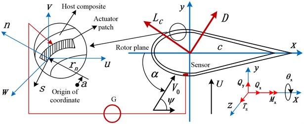
The model of the structure considered is characterized by a number of features: a) the host structure consists of 6 layers CUS configuration and the actuator of 1 piezoelectric layer (the center of the piezoelectric layer width is on the longitudinal coordinate axis, with the sectional height 1.9×10⁻⁴ m and width /6 m) along the circumferential , spanwize and transverse n directions, with sensor distributed symmetrically; the CUS configuration used here consists of in both top side and the bottom; b) the two piezoelectric strip elements may be employed concurrently for sensing and actuation, and related by the voltage produced by the piezoelectric layer to the strain in the host structure; actuator layer and sensor layer are placed symmetrically and integrated as full layers as the CUS configuration in the direction; c) the feedback control mechanism is achieved through the action of piezoelectrically induced vertical transverse shear at the blade tip, considered in conjunction with the implementation of velocity feedback control law; d) the composite properties of blade are: the maximum exterior width of section is 24.21×10⁻³ m; the maximum exterior height is 2.643×10⁻³m; ply thickness is 127×10-6 m; blade length is 0.2 m; blade density is 1672 kg/m3; and other elastic parameters are calibrated as: 3.5 GPa, 0.34, 25.8 GPa, 8.7 GPa, , , .
It should be stated that the two-dimensional constitutive equations, referred to shell-constitutive equations, are applied here, postulating that the hoop stress resultant is negligibly small when compared with the remaining ones in the three-dimensional constitutive equations considering the thickness of the master structure and actuators. In addition, it is assumed that the electric field vector is represented in terms of its component in the direction, coinciding with the direction of thickness polarization. Hence a corresponding boundary moment control strategy [26] is applied here.
Due to the influence of CUS configuration and arrangement of the piezoactuator assumed to be distributed over the entire blade span, a structural tailoring technology can be used according to references [15, 26], with elastic twist and span extension along direction ignored. At the same time, it is firstly assumed that the external pitch angle of the blade is zero, and the relative wind speed is a constant value, which exhibit a weak rigidity in horizontal transverse shear with rotation about direction discarded. Toward the goal of deriving the equations of motion, Hamilton variational principle [15] integrated with the kinetic energy expression and the strain energy function is used.
The expressions of the kinetic energy and the strain energy function can be computed as:
Herein, denotes the Kinetic energy; and are the stress and strain column vectors, respectively; denotes the differential volume elements; denotes the variation operator; the related equation coefficients are computed in Appendix; the equations expressed in terms of one-dimensional stress resultants , and , and stress couples can be expressed as:
where the bending stress and , the transverse shear stress resultant and the stress couple can be written as:
where , are the axial strain components associated with the primary and secondary warping, respectively, while , are the membrane shear strain and transverse shear strain, respectively.
In order to derive the equations of motion and the associated boundary conditions (BCs), consider in conjunction with Eqs. (1a)-(1b)), Hamilton's variational principle is used as follows:
where denotes the prescribed components of the stress vector on a surface element of the undeformed body characterized by the outward normal components ; denotes the components of the body forces including , , , and mentioned above; denotes the external area of the body over which the stresses arc prescribed; denotes the mass density.
In view of the fact that the blade is much stiffer in the longitudinal direction than in the flapping and lagging ones, the effect of the axial inenia term is much smaller as compared to the other ones and can also be discarded. Consider implementing CUS ply-angle scheme and structural tailoring technology, the corresponding equations of motions and BCs can be obtained. The governing equations of motions in vertical bending, lateral bending and transverse shear directions, under the action of aerodynamics, can be directly expressed as:
Vertical bending:
Lateral bending:
Vertical transverse shear deformation:
From variational principle, assuming the blade to be clamped at 0 and free at , the BCs satisfy the reduced equations of motions expressed as:
where:
and the related equation coefficients are computed in Appendix. is the piezoelectrically induced term, the calculation of which is hidden in the calculation of . According to Ref. [15], it can be approximately expressed as:
Herein, and denote local stretching and stretching-bending coupling rigidity quantities, respectively described in Appendix; is a spatial function expressed by Heaviside distribution; is piezoelectric coefficient. is the applied electric field to which the piezoelectrically induced terms are proportional, and depends on the piezoelectric sensor output voltage in proportional control law according to boundary moment control strategy [15]. The voltage across the sensor can be obtained by dividing the charge developed in the sensor by the sensor’s capacitance [15], which is stated as:
where is the piezoelectric patch area. In addition, the other piezoelectric parameters are: Piezoelectric coefficient –2.05×10²Pa V, Piezoelectric density 7.65×10² kg s2/m4, Electrical permittivity 1.2×10⁻⁸F/m, Elastic coefficient 1.39×10¹¹Pa, Elastic coefficient 7.778×10¹⁰Pa.
2.2. Piezoelectric feedback scheme and reduced aerodynamic model
For the problem of piezoelectric feedback control, is different from zero only if external voltage of opposite sign is applied in the upper and bottom piezoactuator layer. For feedback control, the applied electric field on which the piezoelectrically induced moment depends, may be expressed through a prescribed linear functional relationship with the kinematical response quantities characterizing the blade’s response [26]. In the previously displayed equations, due to the special distribution of piezoactuators, the piezoelectrically induced bending moment intervenes solely in the boundary conditions prescribed at the blade tip, hence it plays the role of a boundary moment velocity control [15]. In order to increase the control authority used for displacement measurement, a feedback control scheme is implemented according to velocity control law, with the piezoelectrically induced bending moment at the blade tip expressed as:
where is velocity feedback gain; is a constant dependent upon the mechanical and geometrical properties of piezo-composite structure.
In order to simplify the calculation of the piezoelectric parameters, the width of piezoelectric layer is relatively small, generally less than or equal to 1/6 chord length here. In addition, the feedback gain cannot be changed infinitely because the applied voltage must be limited for the sake of breakdown voltage of actuators. Furthermore, although the improper feedback gains have little effect on the stall flutter in present study, it will cause system crash and bring the singularity failure during numerical simulation. According to the requirements of blade structure and actual control hardware here, the fixed feedback gain of 1 is applied.
For the present stall modeling research, an nonlinear aerodynamic tool is necessary to adequately describe nonlinear stalled aerodynamic loads. The ONERA model has recently become popular in flutter research of wind turbine blade [24]. The original nonlinear ONERA aerodynamic model expressed in lift and moment coefficients has been used along with harmonic balance method for the nonlinear response analysis of fixed wing surfaces [25]. A set of reduced equations can be extracted appropriate for rotary motion without the elastic twist. Aerodynamic expressions of lift and drag are presented as:
where the nonlinear aerodynamic variables are:
Herein, nonlinear parts in aerodynamic variables can be found in reference [24, 25].
3. OLC control
3.1. Discretization and strip decomposition
Approximate processing is applied to deal with the aerodynamics at the right-hand-side terms in Eqs. (2a)-(2c) and realize discretization. The following steps will be implemented [24]. The first step consists of representation of displacement functions in the forms:
where , , are 1× ( 5 is the number of reserved modes) vectors of suitable shape functions.
Applying Galerkin method [24], and substituting Eq. (7) into Eqs. (2) give 3 matrix equations:
A strip theory assumption [24] is used to solve the nonlinear integral expressions at the right-hand-side terms in Eq. (8). The blade is divided into 5 spanwise aerodynamic sections so as to replace the integral operation with summation. Inserting Eq. (6a) into Eqs. (2a)-(2c)) and considering in conjunction with strip forms of the aerodynamic variables in aerodynamic formula of Eqs. (6b)-(6c)), and assuming:
Result in the nonlinear equations governing the motion of the stall aeroelastic system, with 32 sub-equation structures as follows:
In order to carry on subsequent analysis, Eq. (10) needs to be transformed into the state space expression, with 232 50 sub-equation structures as follows:
3.2. Control principle
The optimal theory is often used to analyze vibration control of rotating composite beam. Active damping effect of rotating composite thin-walled beams using MFC actuators and PVDF sensors has been investigated through a velocity feedback control algorithm [8, 9]. It was actually a single feedback gain control, with the electric force directly regarded as a feedback force. In reference [30], an orthotropic host and transversely isotropic sensor-actuator pairs embedded along the span have been considered. The total output from sensors was fed to a controller and then two types of linear quadratic regulator (LQR) methods were used. However, it is a box beam structure. In addition, flutter suppression based on linear quadratic Gaussian (LQG) controller has been investigated in reference [28]. However, the LQG algorithm in present study sometimes causes the system to diverge, and is often accompanied by a large response range.
In order to suppress the too large initial vibration amplitudes in LQR and LQG processes, and decrease the influences of measurement noise (might be produced by unsteady aerodynamics) and disturbance signals (process noise), which are stochastic with known statistical properties and are hidden in system equation, an optimal LQG controller (OLC) is analyzed here by analysis of vibration characteristics and time responses.
It is important to note that the blade does not undergo pitch motion (external pitch angle is equal to zero); the magnitudes and fluctuations of the three displacements of vertical bending (), lateral bending (), and transverse shear () motions are very different, whether they are shown in uncontrolled cases or controlled cases below. This is the characteristics of rigid system. Hence conventional LQG controller [31] is likely to lose its utility, which is another reason for this design using OLC controller.
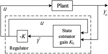
Based on OLC control, full state feedback for all state variables must be executed. The OLC forms a dynamic regulator or compensator and gives a state-space model of the plant, a state-feedback gain matrix , and an estimator gain matrix . The regulator is obtained by connecting the state feedback law and the state estimator with gain matrix . For the plant of Eq. (11), it will yield the regulator:
The regulator should be connected to the plant using positive feedback as Fig. 2. The optimal gain matrix is deduced by LQR controller; is from a Kalman state estimator given a state-space model of the plant and noise covariance data of the process and measurement, which is decided by 1 and unitary matrix . The Kalman estimator provides the optimal solution to the continuous estimation problems of Eq. (11). The state-feedback law minimizes the quadratic cost function:
where satisfies the following Riccati algebraic equations:
where is positive semidefinite matrix. 0.001×eye (); (1, 1) = 10000; 1×10⁻².
In addition, the structural vertical transverse shear deformation can be reflected by the feedback voltage by means of a constant gain. Voltage is expressed by the piezoelectrically induced term by the feedback control scheme in Eq. (5) as:
Fig. 2The regulator of OLC control
4. Numerical simulation and discussions
4.1. Damping ratio and stability
It should be stated that the structural viscoelastic damping of thin-walled composite blade is not considered. The damping item in Eq. (8) is only piezoelectric feedback part of Eq. (5), which is a very small value. Also, aerodynamic damping derived from nonlinear aerodynamics is embodied in Eq. (10), which cannot always completely resist the influences of stall flutter in the cases. So the whole system with piezoelectric actuation always appears divergent. In general, stability analysis for stall nonlinear flutter behavior can be investigated by eigenvalue analysis of the dynamic system in Eq. (10). The solution of the algebraic eigenvalue problem yields the closed-loop eigenvalues of Eq. (10) as:
where , are th damping and frequency of damped oscillation, which depend on the feedback gains , the ply angles and the rotating speeds. If the wind speed is equal to zero, the piezoelectric damping ratio of the th mode can be obtained as:
Fig. 3(a) shows the variation of piezoelectric damping ratios versus ply angles from 0°-90° at interval of 10°, and Fig. 3(b) rotational speeds from 0 r/m-360 r/m at interval of 10 r/m. Note that the wind speed is equal to zero, and the rotating speeds are given artificially in these cases. It can be seen that both the 1st order damping ratio and the 2nd order damping ratio are affected by ply angles, but less influenced by rotating speeds. In subsequent flutter analysis, we can take the cases of ply angle 20° and rotating speed 40 r/m, which produce the larger fluctuations in the 1st order damping ratio curves, as the basic parameters. The cases intended to highlight the effects of OLC control on stall flutter are presented, with apparent changes of piezoelectric feedback voltages demonstrated.
Fig. 4 demonstrates the responses of free vibration of vertical bending (), lateral bending (), and transverse shear () motions, respectively, under the conditions of the basic parameters without wind load. With the change of time, the system is gradually convergent. Especially for displacement of lateral bending (), the magnitude of the vibration amplitude is very small, so the vibration of lateral bending can be approximately ignored under this CUS condition.
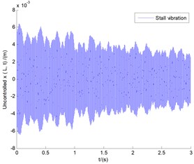
In order to analyze stall flutter, and at the same time for the purpose of comparison with results of Fig. 4, still take the previous case with ply angle 20° for example, meanwhile let blade tip speed ratio 0.1 and wind speed 8.37758 m/s, so still rotating speed is 40 r/m. Fig. 5 demonstrates the time responses of stall vibration of vertical bending (), lateral bending (), and transverse shear () motions, respectively, under the conditions of the basic parameters with wind speed 8.37758 m/s. It can be seen that the displacement of vertical bending () presents the flutter state of equal amplitude vibration, with the vibration amplitude exceeding the length of the blade 0.2 m. This is only the result of the numerical simulation, which in fact depicts a rapid divergence of the unstable state of the displacement [24]. Compared with the lateral bending () in Fig. 4, the lateral displacement in Fig. 5 shows almost the same magnitude and trend, except for some additional high frequency noise hidden in it. This also means that stall flutter will bring about high frequency noise, which is one of the reasons for the subsequent use of OLC controller. In addition, the response of transverse shear () in Fig. 5 shows the flutter state of equal amplitude vibration with greater amplitude in contrast with the former in Fig. 4, which is an obvious state of flutter instability [24].
Fig. 3Piezoelectric damping ratios versus: a) ply angles, b) rotational speeds, respectively
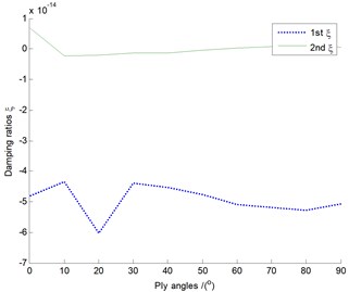
a) Damping ratios versus ply angles
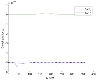
b) Damping ratios versus rotational speeds
Fig. 4The responses of vertical bending (y), lateral bending (x), and transverse shear (θx) motions under the conditions of the basic parameters without wind load
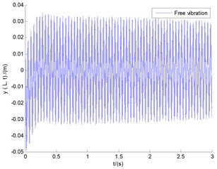
a) Vertical bending
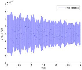
b) Lateral bending
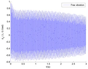
c) Transverse shear
4.2. Effects of conventional LQG controller and OLC control under stall situation
Fig. 6(a) shows the three displacements using conventional LQG controller under the conditions of the basic parameters in Fig. 5. The vibration amplitudes of vertical bending () and transverse shear () exceed far beyond the length limit of the blade 0.2 m, which also demonstrates a state of divergent instability within a very short time, although the LQG control effect is convergent in a long time range. Figs. 6(b)-(d) show the comparisions of displacement responses between LQG controller and OLC cotroller, respectively. The values of the left side of longitudinal coordinates in all the three images show the simulation results of LOG controller, while the right side shows the values of OLC control process. It can be seen that compared with LQG control, the controlled vibration amplitudes of vertical bending () and transverse shear () motions under OLC control are very small and decrease rapidly with the change of time, and tend to be steady in a very short period of time with small displacement deflection. It demonstrates apparent flutter control effects of OLC algorithm on divergent instability. In addition, given that the lateral displacements in Figs. 4-6 are small and of little difference, lateral displacement will be omitted in subsequent studies.
Fig. 5The responses of vertical bending (y), lateral bending (x), and transverse shear (θx) motions under the conditions of the basic parameters with wind speed U= 8.37758 m/s
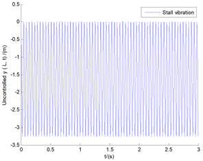
a) Vertical bending
b) Lateral bending
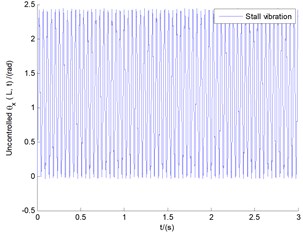
c) Transverse shear
Fig. 7 demonstrates the feedback voltage signals in state of stall flutter corresponding to both LQG control and OLC control, which can in turn theoretically and accurately express the numerical values of vertical transverse shear deformation according to Eq. (15). It is obviously demonstrated that the applied voltages show big differences in LQG control and OLC control. The amplitude from OLC controller decreases rapidly with the change of time, and stabilizes at some smaller value. In contrast with OLC control, the voltage response in LQG control passes through a process of big fluctuation, and gradually decreases, and finally stabilizes at a larger value. This kind of big fluctuation can bring about the collapse of the piezoelectric actuator, so that it cannot reach the purpose of testing displacement.
It should be stated that the application of voltage and feedback law in Eq. (5), is not the fundamental reason of active control for stall flutter. The fundamental reason is the OLC control algorithm itself. Application of voltage and the feedback law here is mainly used as the sensor, and reflects the vertical transverse shear deformation, which can directly reflect the magnitude of the vibration and provide signal to drive external pitch motion in succedent pitch control.
Fig. 6The controlled time responses of vertical bending (y), lateral bending (x), and transverse shear (θx) motions with the tip speed ratio λ= 0.1
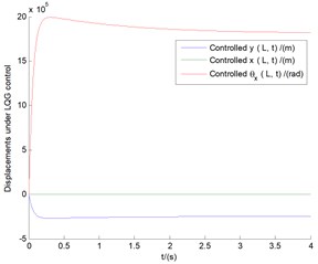
a) Displacements under conventional LQG control
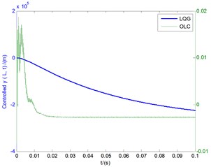
b) Controlled vertical bending
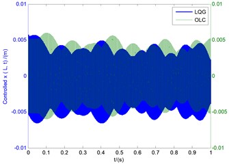
c) Controlled lateral bending
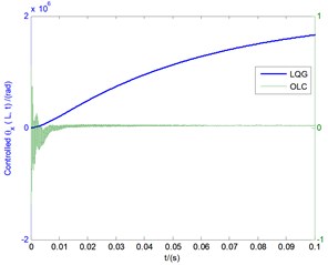
d) Controlled transverse shear deformation
Fig. 7The voltage signals G corresponding to both LQG control and OLC control with the tip speed ratio λ= 0.1
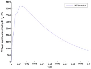
a)
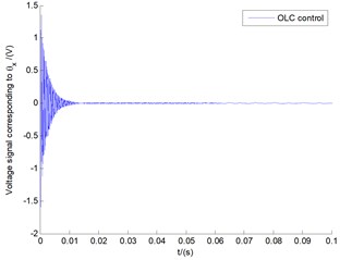
b)
4.3. Fluter suppression under condition of different tip speed ratio
In order to test such OLC control it can be commonly used at that given internal structural parameters and external parameters. Another case of different tip speed ratio 1 is investigated. Fig. 8(a) shows the uncontrolled displacement responses of vertical bending () motion and transverse shear () deformation with equal amplitude oscillations and Fig. 8(b) their limit cycle vibrations with some of the high frequency noise hidden in it.
Due to the fact that the lateral bending displacement itself is relatively too small to be neglected in this case, hence next study mainly focuses on the flutter suppression of vertical bending motion and transverse shear deformation.
Fig. 9 demonstrates the controlled time responses of the two displacements (LQG item is still denoted by the left side of longitudinal coordinates), and phase planes for both LQG controller and OLC control process. It can be found that the effect of LQG controller is very bad, showing a state of divergent instability. Its time response is divergent, with its phase plane unstable. Fine tuning of the , parameters in conventional LQG controller, or directly using of LQG servo controller might improve LQG control performance, but this is a complex process. On the contrary, the response of OLC control presents a state of convergent stability under the same controller parameters. Its phase plane converges throughout the whole time range around point (0, 0). In contrast with conventional LQG controller, the OLC control process is of more advantages in respect of the stability control.
Fig. 8The uncontrolled displacement responses of: a) vertical bending (y) motion and transverse shear (θx) deformation, b) their limit cycles under λ= 1
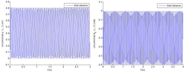
a) Uncontrolled displacement responses of vertical bending () motion and transverse shear () deformation
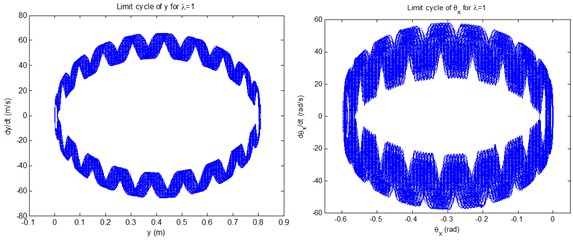
b) Limit cycle vibrations of uncontrolled displacements
4.4. The influence of OLC control on external pitch motion
Reduction in cost of wind energy requires most efficient control technology which can extract optimum power from the wind. In wind energy conversion systems, one of the operational problems is the changeability and discontinuity of wind. Hence, quality of produced energy becomes an important problem in wind energy conversion plants. Pitch control is the most efficient and popular power control method, and has been applied to improve the quality of power generated from wind turbines [32-33]. The most efficient power control and aeroelastic stability are always two contradictory aspects, so the determination of pitch angle requires a compromise selection. The change of piezoelectric feedback voltage (when the value exceeds a certain set point) is used here to drive active pitch controller to improve the aeroelastic stability. Variable pitch system with variable pitch angles is usually a two-order system, with motion law of variable pitch angle implemented usually through fuzzy PID control, neural network control and other intelligent control methods, which are complex processes of dynamic regulation and dynamic change [33, 34]. To simplify analysis, a refined deflection theory (RDT) was developed for predicting the effective elastic stiffness’s under constant pitch angle in the preliminary study of our group members [35].
In present study, considering CUS blade beam with constant pitch angle and carrying out the same RDT analysis, result in the equations governing the system motions of blade tip as follows:
Vertical bending:
Lateral bending:
Vertical transverse shear deformation:
where is the external constant pitch angle.
Fig. 9The controlled time responses and phase planes of: a) vertical bending motion, b) transverse shear deformation, based on both LQG controller and OLC control process under λ= 1
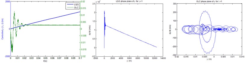
a) The controlled time responses and phase planes of vertical bending () motion based on both LQG controller and OLC control process
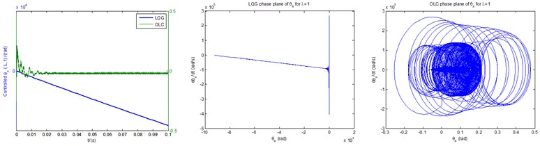
b) The controlled time responses and phase planes of transverse shear deformation () based on both LQG controller and OLC control process
A similar solution procedure above mentioned is applied to Eq. (18) based on the structural parameters and external parameters in section 4.3. The uncontrolled time responses still exhibit equal amplitudes and high frequencies, in view of similarity, which are not shown here.
The controlled time responses of the three motions based on both LQG controller and OLC control process under pitch angles of 30° (a), 40° (b) and 60° (c), can be obtained in Fig. 10, respectively. It is noted that the lateral bending displacements are no longer negligible due to the presence of constant pitch angles. It can be seen from Figs. 10(a), (b) that the vibration amplitudes of both LQG control and OLC control quickly exceeds the length of the blade 0.2 m, which in fact represent rapid divergences of the unstable states of the displacements as depicted in Fig. 5. However, in contrast with the controlled cases of LQG, the displacements controlled by OLC controller are of more advantages from the viewpoint of convergent processes and steady-state values. In particular for OLC controller, the overall trend is convergent and can always be stabilized near zero. Fig. 10(c) demonstrates that in terms of magnitudes or response trends, all displacements of both LQG control and OLC control are convergent and stable. Meantime, more advantages of OLC controllers are demonstrated as well. In addition, it can be seen from Fig. 10 that the influences of pitch angles on stability are significant. The case of Fig. 10(c) 60° shows greater advantages in amplitudes, but in any case, the superiority of OLC control is remarkable.
Fig. 10The controlled time responses of the three motions based on both LQG controller and OLC control process under pitch angles of: a) β= 30°, b) β= 40°, c) β= 60°, respectively
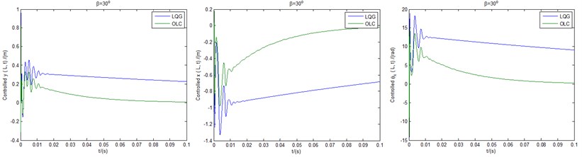
a) Controlled displacements under pitch angle of 30°
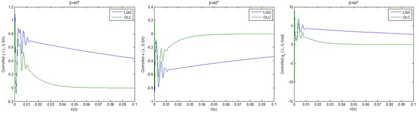
b) Controlled displacements under pitch angle of 40°
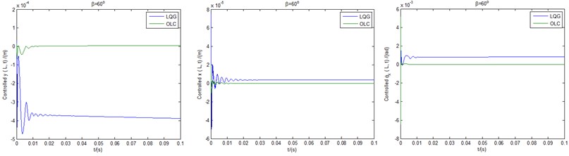
c) Controlled displacements under pitch angle of 60°
In general, the maximum available power is not linearly related to the change of pitch angle. However, the simulation results show that the aeroelastic stability and controllability are increased with the increase of pitch angle in the range of 30°-75°. Therefore, within this range, the maximum power gain is set, and when the voltage exceeds the allowable value, the pitch angle can be increased to improve the aeroelastic stability. In addition, it is noticed that the system is no longer a rigid system due to the existence of external pitch actuator, and the amplitudes and the trends of the three displacements controlled by both LQG and OLC show the same order of magnitude. Therefore, the LQG controller can also play a certain role, although its control effect is inferior to OLC controller.
5. Analytical proof of the structural modeling and feasibility analysis of physical realization of the OLC algorithm
5.1. Validation of modeling
This ply-angle distribution referred to as CUS configuration is achieved by skewing angle plies with respect to the blade axis according to the law in the top (above the chord) and bottom flanges. With structural tailoring implemented, the structural couplings of bending-twist and extention-twist vibrations are neglected. Also discarded is lateral transverse shear deformation. The governing equation of Eq. (2) without pitch motion is obtained from variational principle. The equation of Eq. (18) with constant pitch angle is obtained from RDT theory, which is actually an ideal theory of linear deformation.
However, there is an inevitable connection between these two theories. Let 0°, Eq. (18a) and Eq. 18(c) are completely reduced to Eq. (2a) and Eq. (2c), respectively. As for Eq. (18b), a redundant item of is retained, which corresponds exactly to the redundant item of in Eq. (2b). This might be due to the higher order warping effect that is not included in the STD theory itself. However, they can approximately agree with each other.
5.2. Real-time OLC process
Based on OLC controller, full state feedback for all state variables must be executed. Meanwhile the feedback of as many as 2 nonlinear aerodynamic variables and 3 structural variables is difficult in practice, i.e. in the real-time OLC process. Especially for aerodynamic variables, it is difficult to have ready-made instruments to measure them. However, for this reduced stall aerodynamic model, the error between full state feedback and physically achievable structural feedback is relatively small, which can be verified by simulation.
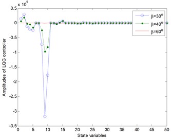
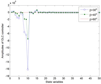
Take the basic structural parameters and external parameters in Section 4.4 for example, Fig. 11 illustrates controller amplitudes vs. 50 state variables of both LQG controller and OLC controller. The controller amplitude here is referred to the maximum value of the time domain fluctuation of the control signal corresponding to each controlled variable. Notice that the values of horizontal coordinate are denoted in turn by 50 state variables, which are 5 vertical bending variables, 5 lateral bending variables, 5 vertical transverse shear variables, 10 aerodynamic variables, and derivatives of all these 25 variables. Not only are the controller amplitudes of the 10 aerodynamic variables very small, but also the amplitudes of the derivatives of all variables are very small. Therefore, in real time control, only sensing, measurement and feedback control for the first 15 structural variables are needed.
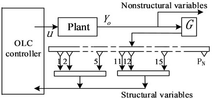
Furthermore, in the cases of previous analysis without external pitch motion, the amplitudes of lateral bending vibrations are very small (the corresponding controller magnitudes are bound to be smaller, which are not involved here) and can be neglected. Hence in these cases, only 5 vertical bending variables and 5 vertical transverse shear variables need to be controlled. Real-time implementation of control algorithm is completely feasible. Hence the control process of real-time OLC control (without pitch motion) can be described in Fig. 12. In this real-time design, the state feedback of output variables includes only feedback of two types of structural variables: vertical bending variables (output ports 1-5) and vertical transverse shear variables (output ports 11-15).
Based on the basic parameters in Section 4.3, Fig. 13 demonstrates the real-time effects of controlled displacements of vertical bending () with its real-time phase plane (a), and vertical transverse shear deformation () with its real-time phase plane (b). Compared with Fig. 9(a), the amplitude of vertical bending () of real-time control in Fig. 13(a) looks a bit larger, which reflects a slight lack of control performance. However, the overall trend is consistent and convergent, which indicates consistency for stability control. The phase plane of vertical bending () in Fig. 13(a) still converges around point (0,0) with smaller frequency fluctuations. The same analysis and conclusions are appropriate to Fig. 9(b) and Fig. 13(b).
Fig. 11The response amplitudes of the controller itself of both LQG control and OLC control
a)
b)
Fig. 12The scheme of real-time OLC process (without pitch motion)
5.3. Experimental platform
Validation of modeling of blade body and real-time process of OLC algorithm have been discussed and proved in Sections 5.2-5.3. The large wind turbine is mostly controlled by PLC system, some intelligent control algorithms cannot be implemented in PLC hardware because of their complexity. Therefore, it is necessary to further discuss the feasibility analysis of the hardware implementation of OLC process.
In present study, an experimental platform is built by PLC system and MATLAB-OPC server [36] to test the feasibility of hardware implementation. OPC is a series of seven specifications defined by the OPC Foundation for supporting open connectivity in industrial automation and uses Microsoft DCOM technology to provide a communication link between OPC servers and OPC clients. OPC technology allows data, drawn from live servers and data historians that conform to the OPC Data Access standard, the OPC Historical Data Access standard, and the OPC Unified Architecture standard, to be shared [36]. Fig. 14(a) shows the hardware of experimental platform that consists of PLC controller cabinet (integrated with CPU224XP module and relay group), touch screen hardware and MATLAB simulation environment. The CPU module runs the entire OLC algorithm, sends output signal to MATLAB simulation environment to drive the aeroelastic system and accepts the signal which is exactly the output of aeroelastic system in simulation environment. The entire aeroelastic system model is run in computer. The signals of the control process can be displayed by touch screen hardware which is connected to CPU module.
Fig. 13Responses and phase planes of displacements controlled by real-time OLC control
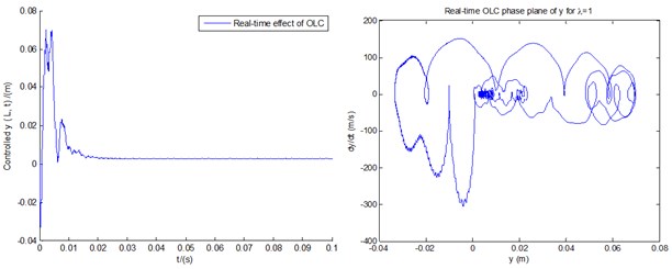
a) Response and phase plane of vertical bending controlled by real-time OLC control
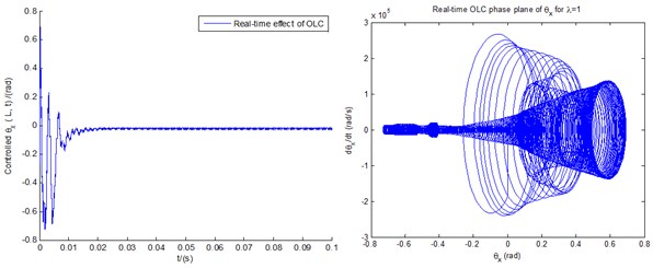
b) Response and phase plane of transverse shear controlled by real-time OLC control
Fig. 14The experimental platform
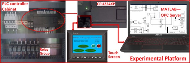
a) The hardware of experimental platform
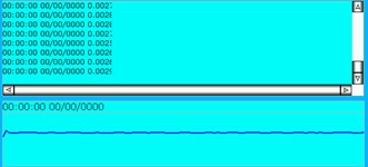
b) Response of vertical bending ()
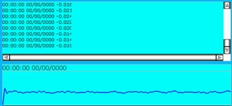
c) Response of vertical transverse shear deformation ()
Based on the basic parameters in Section 5.2, Figs. 14(b)-(c) reproduce the real-time effects of the controlled displacements of vertical bending () and vertical transverse shear deformation (), respectively. Compared with Fig. 13(a), the amplitude of vertical bending () of real-time control in Fig. 14(b) cannot show initial fluctuations within the time range of [0 0.01 s] as displayed in Fig. 13(a), which is due to the minimum sampling time of the touch screen being 0.1 s. However, the overall trend and fluctuation amplitudes in the time range of [0.01 s, ] in Fig. 14(b) are still consistent with those in Fig. 13(a). Furthermore, the displacement response in Fig. 14(b) fluctuates at a steady value of 0.02, which coincides with the conclusion shown in Fig. 13(a). What's more, Fig. 14(b) can show specific values of output fluctuations and make the response results more visualized. Compared with Fig. 14(b), Fig. 14(c) shows a wider range of fluctuation amplitudes (within the scope of [–0.02 rad, –0.01 rad]) of steady-state value, which is also consistent with the response scope of vertical transverse shear deformation () in Fig. 13(b). Similarly, the fluctuations in the time range [0, 0.01 s] in Fig. 13(b) are not shown in Fig. 14(c), because of the minimum sampling time of the touch screen being 0.1 s.
The experimental platform not only proves the feasibility of physical realization of the OLC algorithm based on hardware implementation, but also verifies the validation of simulation of OLC algorithm. The experimental platform can directly output and display the specific values of displacement signals by touch screen.
6. Conclusions
In this study, stall nonlinear flutter behavior and flutter suppression by conventional LQG controller and OLC control process for piezo-composite rotor blade are investigated by numerical simulation. Some concluding remarks can be drawn from the results:
1) Structure and motion of piezo-composite blade with couplings among vertical bending, lateral bending and vertical transverse shear deformation are investigated and discussed based on CUS configuration. Galerkin method and strip theory are applied to realize discretization and aerodynamic decomposition.
2) The piezoelectric feedback itself is used as a sensor to accurately express the displacement signal, rather than as the conventional active actuator depicted in reference [20]. In other words, piezoelectric actuation itself is not of much significance in stall flutter suppression. However, the change of piezoelectric feedback voltage is used here to drive the pitch controller to make reduction in cost of wind energy and improve the aeroelastic behavior.
3) Aeroelastic control is realized by both LQG controller and OLC control process. For OLC control, flutter suppression effect on vibration amplitude is obvious, especially for rigid system. In the cases with relatively larger tip speed ratio, LQG control might not change the system divergent instability, even bring about counterproductive effects. Repeated simulation results show that the OLC control effect is not sensitive to tip speed ratio, even to the variations of internal structural parameters and external parameters in a certain range, which means greater advantage in aeroelastic control.
4) In view of extracting optimum power from the wind, the constant pitch angle is set here to improve quality of produced energy and aeroelastic stability. In the course of pitch motion, OLC control also demonstrates positive advantages. In addition, real-time effect of OLC control is discussed, with its experiment platform built. It can provide a physically feasible approach for similar linear quadratic control strategies in the implementation of other engineering problems.
References
-
Andersen P. B., Henriksen L., Gauna M., et al. Deformable trailing edge flaps for modern megawatt wind turbine controllers using strain gauge sensors. Wind Energy, Vol. 13, 2010, p. 193-206.
-
Cooperman A., Martinez M. Load monitoring for active control of wind turbines. Journal of Renewable and Sustainable Energy, Vol. 41, 2015, p. 189-201.
-
Mingming Z., Bin T., Jianzhong X. Parameter study of sizing and placement of deformable trailing edge flap on blade fatigue load reduction. Renewable Energy, Vol. 77, 2015, p. 217-226.
-
Ng B. F., Palacios R., Kerrigan E. C., et al. Aerodynamic load control in HAWT with combined aeroelastic tailoring and trailing-edge flaps. Wind Energy, Vol. 19, Issue 2, 2016, p. 243-263.
-
Li N., Mark J. B., Yang H., et al. Numerical investigation of flapwise-torsional vibration model of a smart section blade with tab. Shock and Vibration, 2015, p. 136026, https://doi.org/10.1155/2015/136026.
-
Chandiramani N. K., Librescu L., Saxena V., et al. Optimal vibration control of a rotating composite beam with distributed piezoelectric sensing and actuation. Smart Materials and Structures, Vol. 13, 2014, p. 433-442.
-
Mira M., Gopalakrishnan S., Bhat M. S. Vibration control in a composite box beam with piezoelectric actuators. Smart Materials and Structures, Vol. 13, 2004, p. 676-690.
-
Choi S. C., Park J. S., Kim J. H. Active damping of rotating composite thin-walled beams using MFC actuators and PVDF sensors. Composite Structures, Vol. 76, 2006, p. 362-374.
-
Choi S. C., Park J. S., Kim J. H. Vibration control of pre-twisted rotating composite thin-walled beams with piezoelectric fiber. Composite Structures, Vol. 300, 2007, p. 176-196.
-
Song Z. G., Li F. M. Aerothermoelastic analysis and active flutter control of supersonic composite laminated cylindrical shells. Composite Structures, Vol. 106, 2013, p. 653-660.
-
Huishen S., Deqing Y. Nonlinear vibration of anisotropic laminated cylindrical shells with piezoelectric fiber reinforced composite actuators. Ocean Engineering, Vol. 80, 2014, p. 36-49.
-
Lucy E. A., Haim A. Augmented damping of a piezo-composite beam using extension and shear piezoceramic transducers. Acta Mechanica, Vol. 191, 2007, p. 37-58.
-
Kapuria S., Yasin M. Y. Active vibration suppression of multilayered plates integrated with piezoelectric fiber reinforced composites using an efficient finite element mode. Journal of Sound and Vibration, Vol. 329, 2010, p. 3247-3265.
-
Phung P. V., Lorenzis L. D., Chien H. T., et al. Analysis of laminated composite plates integrated with piezoelectric sensors and actuators using higher-order shear deformation theory and isogeometric finite elements. Computational Materials Science, Vol. 96, 2015, p. 495-505.
-
Song O., Librescu L., Oh S. Y. Vibration of pretwisted adaptive rotating blades modeled as anisotropic thin-walled beams. AIAA Journal, Vol. 39, Issue 2, 2001, p. 285-295.
-
Chandiramani N. K., Chandrashekhar D. S., Librescu L. Vibration of higher-order-shearable pretwisted rotating composite blades. International Journal of Mechanical Sciences, Vol. 45, 2003, p. 2017-2041.
-
Mahato P. K., Maiti D. K. Aeroelastic analysis of smart composite structures in hygro-thermal environment. Composite Structures, Vol. 92, 2010, p. 1027-1038.
-
Song Z. G., Li M. F. Active aeroelastic flutter analysis and vibration control of supersonic composite laminated plate. Composite Structures, Vol. 94, 2012, p. 702-713.
-
Li M. F. Active aeroelastic flutter suppression of a supersonic plate with piezoelectric material. International Journal of Mechanical Sciences, Vol. 51, 2012, p. 190-203.
-
Qiao Y. H., Han J., Zhang C. Y., et al. Active vibration control of wind turbine blades by piezoelectric materials. Chinese Journal of Applied Mechanics, Vol. 30, Issue 4, 2013, p. 587-592.
-
Dipali T., Ranjan G. Induced shear actuation of helicopter rotor blade for active twist control. Thin-Walled Structures, Vol. 45, 2007, p. 111-121.
-
Park J. S., Kim J. H. Design and aeroelastic analysis of active twist rotor blades incorporating single crystal macro fiber composite actuators. Composite Part B, Vol. 39, 2008, p. 1011-1125.
-
Dunnmon J. A., Stanton S. C., Mann B. P., et al. Power extraction from aeroelastic limit cycle oscillations. Journal of Fluids and Structures, Vol. 27, 2011, p. 1182-1198.
-
Liu T., Ren Y., Yang X. Nonlinear aeroelastic stability analysis of wind turbine blade with bending-bending-twist coupling. Journal of Fluids and Structures, Vol. 43, 2013, p. 488-502.
-
Taehyoun K. Nonlinear Large Amplitude Structural and Aeroelastic Behavior of Composite Rotor Blades at Large Static Deflection. Ph.D. Thesis, Massachusetts Institute of Technology, Cambridge, Massachusetts, 1992.
-
Sungsoo N. Control of Dynamic Response of Thin-Walled Composite Beams Using Structural Tailoring and Piezoelectric Actuation. Ph.D. Thesis, Virginia Polytechnic Institute and State University, 1997.
-
Yumeng Y., Weiqiang L., Dewei Z., et al. An organic-inorganic perovskite ferroelectric with large piezoelectric response. Science, Vol. 357, Issue 6348, 2017, p. 306-309.
-
Qian W., Huang R., Hu H., Yonghui Z. Active flutter suppression of a multiple-actuated-wing wind tunnel model. Chinese Journal of Aeronautics, Vol. 27, Issue 6, 2014, p. 1451-1460.
-
Wu X., Jin C., Wenzhong S., et al. Integration study on airfoil profile for wind turbines. China Mechanical Engineering, Vol. 20, Issue 2, 2010, p. 211-213.
-
Shete C. D., Thiruvananthapuram, Chandiramani et al. N. K. Optimal control of a pretwisted shearable smart composite rotating beam. Acta Mechanica, Vol. 191, 2007, p. 37-58.
-
Linear-Quadratic-Gaussian (LQG) design. Mathworks, https://www.mathorks.com/help/control/ ref/lqg.html?searchHighlight=lqg&s_tid=doc_srchtitle.
-
Saravanakumar R., Jena D. Validation of an integral sliding mode control for optimal control of a three blade variable speed variable pitch wind turbine. Electrical Power and Energy Systems, Vol. 69, 2015, p. 421-429.
-
Yilmaz A. S., Özer Z. Pitch angle control in wind turbines above the rated wind speed by multi-layer perceptron and radial basis function neural networks. Expert Systems with Applications, Vol. 36, 2009, p. 9767-9775.
-
Liu T. The limit cycle oscillation of divergent instability control based on classical flutter of blade section. Journal of Vibroengineering, Vol. 19, Issue 7, 2017, p. 5114‑5136.
-
Liu T., Wei X. Flap/Lag stall flutter control of large-scale wind turbine blade based on robust H2 controller. Shock and Vibration, 2016, p. 8378161.
-
OPC Toolbox. Mathworks, http://cn.mathworks.com/help/opc/index.html.
Cited by
About this article

This work is supported by the National Natural Science Foundation of China (Grant No. 51675315), and the Natural Science Foundation of Shandong Province of China (Grant No. ZR2013AM016).
