Abstract
Segmental tunnel is common in subway tunnel engineering, which is at risk of being attacked by terrorists’ bombing and accidental explosions. Due to the discreteness of segmental tunnel lining, it’s difficult to model its dynamic response to internal blast loading. In this paper, a simplified equivalent model was proposed to model the segmental tunnel lining’s vibration response to axisymmetric internal blast loading. This model can account for joints’ reduction of lining’s sectional rigidity, and concentrations of stress and strain on joints can be calculated. This research may aid in protective design and hardening measures for critical part of subway tunnels of segmental lining structure.
1. Introduction
Past 20 years witnessed a drastic increase in terrorist bombing attacks on subway systems in many big cities worldwide [1]. Besides purposed attacks, accidental explosions may be another potential hazard for subway tunnel structures.
In soft soil areas, shield tunneling technique is commonly used due to its advantage of minor influence on surface ground. For these tunnels, the lining is jointed with discrete precast reinforced concrete segments by steel bolts. In the designing codes of segmental tunnel lining, natural hazards including seismic events and man-made disturbances like fires, etc., are generally accounted for in the designing procedure, whereas blast loading was seldom considered for civilian tunnels [2]. Therefore, safety of municipal tunnels under explosions needs more attentions.
By far segmental tunnel linings’ response to internal explosions are seldom explored. It behaves different from monolithic linings due to the fact that the stiffness of the joints is much lower than that of RC segments. Because of this characteristic, Janβen [3] proposed to model radial joints with rotational spring hinges, while the segments can be treated as rigid body. Another similar and improved beam-spring model of segmental lining which can also account for the deformation of the segments attained wide use, especially in Japan [4]. These models are generally for designing procedure of segmental tunnel under static loads from surrounding soil. However, the dynamic responses of segmental tunnels in soil is not fully explored. Y. S. Karinski et al. [5] modelled the joints as elasto-plastic hinges to investigate dynamic responses of lining under seismic loading, which showed that joints render the lining ring more flexible, thus reducing stress in the lining. Jianfei Lu et al. [6] modelled segmental tunnel lining under seismic loads with piecewise curved beams, concluding with similar remarks to that of Y. S. Karinski et al. Recently, on the basis of matrix mechanics method, Ngoc Anh Do et al. [7, 8] studied the behaviour of segmental linings under pseudo-static seismic loading. However, most of these researches are for loads from outside, i.e. static loads from rock or soil strata weights and water pressure, or seismic loading which can be treated as equivalent static loading. Those cases are quite different from the problem of internal explosion for two reasons. First, the explosive loading, with extremely high magnitude and loading rate, can hardly be treated as static forces, and the inertia forces involved are not negligible in the transient process. The second reason attributes to the difference of deformation mechanism between that under loads from outside and internal pressure loads. Under external static loads, the lining is roughly under compression, while under internal blast loading the cylindrical structure tend to expand radially, thus incurring a tensile stress in circumferential direction [9]. Concrete materials generally have high compressive strengths but very low tensile strengths, if the loading is within the capacity of the structure’s strength, then it should behave like “breathe”, otherwise it shall be breached or torn apart. In the process of the vibration of lining wall, on the section of lining thickness, it’s generally under tension and contraction. When it expands radially, the tension on the lining’s hoop direction is dominated by the joint steel bolts, while in contraction the compression is fully assumed by the concrete segment.
Matteo Colombo et al. [9, 10] studied internal blast effects on segmental tunnel with equivalent beam elements modelling ring joints and linear elastic springs to simulate ground-lining interaction, which showed that under internal blast pressure the lining is subjected to tensile force in circumferential direction. Cheng et al. [11] carried out full scale tests on staggered segmental tunnel’s response to internal point-source explosion, concluding that damage mainly concentrate in radial joint areas due to strain concentration.
In this paper, a statistically equivalent continuous model was proposed for segmental tunnel under uniform internal explosive loading, which is an axisymmetric plane problem. The soil’s effect was modelled with unidirectional linear elastic Winkler soil spring which only has compressive strength, together with a wave impedance. The explosive loading was described by a classical simplified model. The problem was solved with Forward Euler explicit method. Some results of numerical calculation and parameter study were also given and discussed. This research may aid in explosion hazard assessment and protective design of some critical subway tunnels.
2. Description of axisymmetric internal blast loading
Considering a centre line charge of explosive [12], cylindrical blast wave will be produced by the explosion and blast loading acts uniformly on the inner wall. However, due to the confinement of the tunnel wall, after the initial reflection of incident blast wave front on the wall, the reflected wave will move inwards, causing an implosion in the centre, then reflected wave move radially and outwards, which will be reflected on tunnel wall again. During propagation, blast wave attenuates, and due to the loss of heat, blast wave dies out gradually.
For blast loads, overpressure and duration of positive phase are two key parameters, and the effective loads acts on a structure is the reflected overpressure. The characteristics of a typical normal incidence and reflection of a blast wave are depicted in Fig. 1, where incident overpressure could be estimated with empirical equation given by Henrych [13]:
where is scaled distance, with and denoting stand-off distance (m) to the centre of explosive charge and weight of the charge (kg). The positive duration of blast wave overpressure can be estimated with [13]:
Concerning effective blast loading working on the inner wall of the structure, which is due to the reflection of incident blast wave on the wall. For a centre line charge detonation, the axisymmetry renders normal reflections on all locations of the inner wall, thus allowing to calculate the reflected overpressure with following empirical formula [13]:
where is incident overpressure, is ambient atmospheric pressure.
Due to multiple reflection [12, 14] in the confined space, the loading enhancement could be accounted for with simplified method proposed by W. E. Baker [14] as shown in Fig. 2, three reflections are considered. The initial reflection could be calculated with aforementioned empirical formula, while the second and third one has the same positive duration like the initial reflection but also a lag one after another, with amplitude halved sequentially. Therefore, with this model, the reflected impulse acting on the structure is enhanced by a factor of 1.75.
Fig. 1Blast wave and its reflection
Fig. 2Baker’s model for internal blast loading in a close-end cylindrical containment
3. Equivalent model for a segmental tunnel
In simplified analyses, when the ratio of thickness to radius of the tunnel it can be modelled with thin shell. In this section, starting from isotropic elastic thin shell model, a statistically equivalent continuous shell model for segmental tunnel lining was derived.
3.1. Continuous cylindrical thin shell
For a continuous cylindrical thin shell, for axisymmetric problem the governing equation of its motion has the following form:
where is mass density of the shell, is radial displacement, and is its radial acceleration, is the blast loading, is resistance pressure from surrounding soil, and is circumferential stress in shell, is Young’s modulus of shell material. Knowing , we have:
For very small Poisson ratio, some researchers [15] also proposed it as:
where , , is the natural frequency of the shell.
3.2. Equivalent for segmental tunnel
In a segment lining with segments and thus joints, as shown in Fig. 3, due to the existence of joints, the ring of lining can be divided into two zones, i.e., joint zones and concrete segment zones, assuming that each joint zone has an equal length of and each concrete segment zone .
Fig. 3Diagram of a segmental tunnel under axisymmetric explosive loading
Given following relationships:
where , are thicknesses, , are Young’s moduli, is the radii of the tunnel, the subscript refers to joint bolt, while refers to concrete segment, , , , are dimensionless ratio coefficients.
According to the geometrical condition:
Neglecting the distortion due to the discreteness incurred by the joint, giving an axial radial expansion displacement, then the circumferential strain:
where is the elongation in circumferential direction, and it can be divided into two parts as:
which , are the strains of each steel bolt-effective zone and concrete segment zone, respectively. Substituting Eq. (8) into Eq. (10) we arrive at:
Considering the force equilibrium on section of thickness:
Substituting Eq. (12) into Eq. (11):
From Eq. (13) we have.
For the radial displacement, we also have:
where is the equivalent modulus of the shell during radial expansion. With given conditions, we can get:
These equations are only valid for expansion movement. When the shell vibrates inwards, i.e. , the compression is assumed by the concrete segment, i.e. . Unifying expansion and rebounding we have:
where denotes Heaviside function.
4. General motion equation in soil
In this paper, the shell-soil interaction is modelled with a unidirectional linear elastic Winkler spring together with a wave impedance. The viscous resistance part due to wave impedance could be written as [12]:
where , , are density of soil, shell radial velocity, dilatational wave speed in soil, respectively.
During the expansion of the shell, the soil is under compression, a rigid shell-soil contact was assumed [12]. Similar to that of monolithic thin shell, the motion equation of segmental lining should have the following form:
where is dilatational stiffness of soil spring, which can be calculated according to Penzien [16] as:
where and are Young’s modulus and Poisson’s ratio of elastic soil. The hoop stress for , thus Eq. (18) could be further written as:
Notice that the inertia term of steel bolts was neglected due to their lightness compared to the massive concrete segments.
If we consider the initial stress due to soil pressure, then , where is the initial soil pressure due to its weight, which can be estimated with , where is weight of unit-depth soil, is the burial depth of the tunnel centre axis.
However, during the rebounding of the shell, the hoop stress become compression, neglecting the influence of discreteness, the joints are in close contact like a monolithic thin shell. In addition, in the process of rebounding, the soil provides no tensile resistance, hence the motion equation takes the following form:
Unifying the aforementioned two equations for radial expansion and contraction results at:
where , thus the complete form of Eq. (22) is as follows:
where is Heaviside function, being introduced to model the soil behavior more precisely.
If we substitute the relationships Eq. (7) between those parameters, we have:
5. Numerical procedure for solution
From Eq. (24) we have:
Simply denoted with:
where with radial outwards from the initial location as positive, stress with tension as positive.
With Eq. (25), and explicit scheme of Forward Euler method can be adopted to solve this system.
At initial time, the system has the initial conditions as , because it needs some time to accelerate to have a velocity to move. It’s easy to find:
Assuming a linear constant acceleration then , . Similarly, we can find results for , , at all time steps.
6. Numerical results and analyses
Consider a segmental tunnel with each ring consisted of 6 segments, all the parameters for calculation are listed in Table 1.
Table 1Parameters for calculation
(m) | (GPa) | (kg/m3) | (GPa) | (MPa) | (kg/m3) | (MPa) | (ms) | |||||
3.0 | 0.01 | 0.94 | 0.1 | 30 | 2700 | 0.2 | 210 | 30 | 1900 | 0.3 | 2.0 | 3 |
In order to study the effect of impulse enhancement due to confined explosion on structural responses, the blast loading with only initial reflection and three-reflections model proposed by W. Baker [14] were adopted for comparison.
Structural responses including radial displacement and velocity are plotted in Fig. 4, and Fig. 5, respectively. It can be seen that the amplitude of the expansion reaches nearly 0.5 cm, while the maximum radial velocity values about 2.5 m/s. With Baker’s simplified model of internal blast loading, the initial amplitude of displacement and velocity are almost the same. However, in latter vibration period, the impulse enhancement has an effect on the amplitude of vibration, which could be observed both in time histories of displacement and velocity. Due to the impedance of the soil, the movement stops gradually, which becomes negligible after 25 ms.
Fig. 4Radial displacement of the lining with different loading model (Baker’s simplified model for internal explosion and single reflection model for explosion in free field)
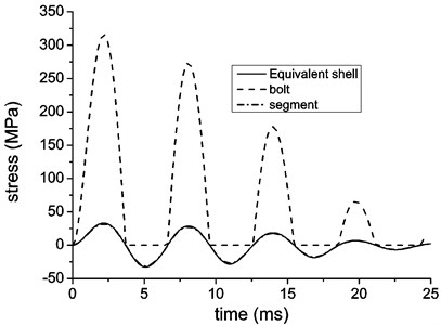
The hoop stress of equivalent shell and structural components with different loading model accounted for are plotted and compared in Fig. 6, and Fig. 7, respectively. The stress concentration on joint bolts are evident to find, which is almost 10 times larger than the stress in reinforced concrete segment. However, it should be noted that the bolts only undergo positive hoop stress, which is the results of the deformation mechanism elaborated in first section, i.e., the bolts can only assume tensile hoop stress during the expansion of the lining ring, while during the contraction all the compressive stress is assumed by the reinforced concrete segment. Like displacement and velocity responses, the impulse enhancement with Baker’s model magnified the amplitude of stress after initial peak, with the initial crest of the waveform curve almost the same.
Fig. 5Radial velocity of the lining with different loading model (Baker’s model considers three reflections, another is single reflection in free field)
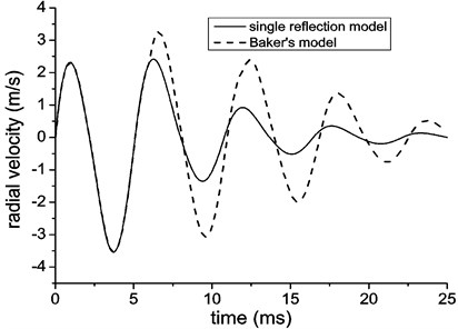
Fig. 6Hoop stress of equivalent shell and structural components with a single reflection loading model in free field
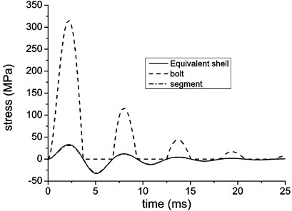
Fig. 7Hoop stress of equivalent shell and structural components with loading of Baker’s simplified model
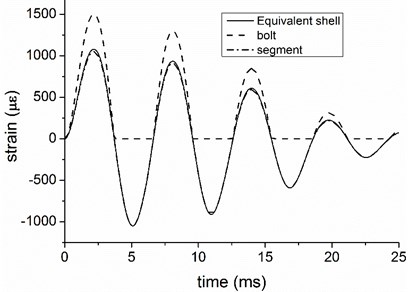
The comparison of strain results is displayed in Fig. 8 and Fig. 9, which generally convey similar information like that by the stress curves, i.e., Baker’s simplified model for internal blast loading mainly take effects after the initial period. However, the strain value on bolts does not contrast that on segment so much like stress results. This is because the stress results are the results of multiplication of strain and elastic modulus, and there is a big gap between these two materials’ modulus. Anyhow the concentration of hoop strain on joint bolt is objective and was observed in authors’ full-scale tests, this may help to explain the damages concentrated in joint areas after an internal explosion [11].
Fig. 8Hoop strain of equivalent shell and structural components with a single reflection loading model in free field
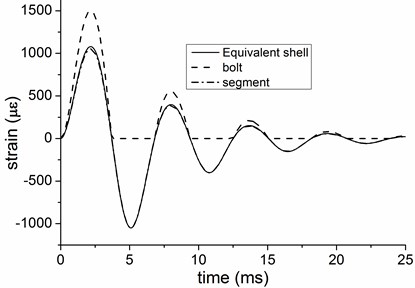
Fig. 9Hoop strain of equivalent shell and structural components with loading of Baker’s simplified model
7. Conclusions
In this paper, a statistically equivalent continuous thin shell model was developed for a segmental tunnel lining under axisymmetric internal blast loading, which accounted for the effect of joint area in the process of circumferential deformation. The soil’s effects were modelled with a unidirectional linear elastic Winkler spring and a wave impedance. The internal blast loading of both Baker’s model with three reflections for cylindrical confinement and single reflection in free field were adopted and compared. The system was solved with a Forward Euler explicit method and numerical results were analysed. Some concluding remarks are given as follows:
1) Assuming an axisymmetric condition, this model was developed on a basis of statistical equivalence, which consider the effects from main structural components including concrete segments and joint bolts;
2) Axisymmetric expansion and contraction has different mechanism. During the deformation process of expansion, the joint bolt’s stiffness play a pivotal role, while in contraction phase, only the concrete segments take effect to assume all the compression;
3) The results show evident concentration of stress and strain on joint bolts, which can explain some test results reported by the authors before;
4) Baker’s simplified model for internal blast loading of cylindrical containment enhances the impulse, thus magnifying structural responses. However, it needs more study to determine whether it only influence the responses after the first period.
References
-
Security for Railways and Metros. Ansaldo STS SpA, Genoa, Italy.
-
Takano Y. Guidelines for the design of shield tunnel lining. Tunnelling and Underground Space Technology, Vol. 15, 2000, p. 303-331.
-
Janβen P. Load Capacity of Segment Joints. Ph.D. Thesis, Braunschweig University of Technology, 1983.
-
Koyama Y. Present status and technology of shield tunneling method in Japan. Tunnelling and Underground Space Technology, Vol. 18, 2003, p. 145-159.
-
Karinski Y., Yankelevsky D. Dynamic analysis of an elastic–plastic multisegment lining buried in soil. Engineering Structures, Vol. 29, 2007, p. 317-328.
-
Lu J., Jeng D., Lee T. L. Dynamic response of a piecewise circular tunnel embedded in a poroelastic medium. Soil Dynamics and Earthquake Engineering, Vol. 27, 2007, p. 875-891.
-
Do N.-A., Dias D., Oreste P., Djeran Maigre I. 2D numerical investigation of segmental tunnel lining under seismic loading. Soil Dynamics and Earthquake Engineering, Vol. 72, 2015, p. 66-76.
-
Do N. A. Numerical Analyses of Segmental Tunnel Lining under Static and Dynamic Loads. Lyon, INSA, 2014.
-
Colombo M., Martinelli P., Di Prisco M. A design approach for tunnels exposed to blast and fire. Structural Concrete, Vol. 16, Issue 2, 2015, p. 262-272.
-
Colombo M., Martinelli P., Huaping R. Pressure-impulse diagrams for SFRC underground tunnels, Computational Modelling of Concrete Structures, 2014, p. 1023-1030.
-
Zhao Y., Chu C., Yi Y. Study on an engineering measure to improve internal explosion resistance capacity of segmental tunnel lining structures. Journal of Vibroengineering, Vol. 18, 2016, p. 2997-3009.
-
Feldgun V., Kochetkov A., Karinski Y., Yankelevsky D. Internal blast loading in a buried lined tunnel. International Journal of Impact Engineering, Vol. 35, 2008, p. 172-183.
-
Henrych J., Abrahamson G. The dynamics of explosion and its use. Journal of Applied Mechanics, Vol. 47, 1980, p. 218-218.
-
Baker P. C. W., Westine P., Kulesz J., Strehlow R. Explosions Hazards and Evaluation. Elsevier, 1983.
-
Gao M. Investigation on Transient Problem of Soil-Lining Structure Dynamic Interaction. Civile Engineering, Tongji University, Shanghai, 2009.
-
Penzien J., Wu C. L. Stresses in linings of bored tunnels. Earthquake Engineering and Structural Dynamics, Vol. 27, 1998, p. 283-300.
Cited by
About this article

This research is supported by Natural Science Foundation of China (Project No. 51478469 and No. 51021001), the support from CSC Scholarship (No. 201503170208) is also acknowledged by the authors.
