Abstract
In this study, experiments were conducted on five specimens of stiffened and unstiffened steel plate shear walls under cyclic loading. First, the specimens and frame design, material properties, and test setup were described. The behaviors of the unstiffened aluminum and steel infill plates were compared with three configurations of stiffened steel plate, i.e., cross-stiffened, circular-stiffened, and diagonally stiffened. The cross-sectional areas of the stiffeners were the same for all stiffened specimens. The results showed that the aluminum infill plate exhibited less ductility. By contrast, the unstiffened steel plate was very ductile, exhibiting a stable hysteresis curve and no tearing. The energy-absorption capacity of the steel plate shear walls increased for all stiffening configurations. Among all configurations, the cross-shaped stiffeners showed considerable increase in shear stiffness, ductility, and energy-dissipation capacity. The plate frame interaction method could predict the ultimate shear strengths of the unstiffened and cross-stiffened panels with good precision. The circular-stiffened steel shear wall seems to behave more desirably in high-amplitude displacements.
1. Introduction
Owing to the excellent seismic performance of steel plate shear walls, they are considered a desirable choice for lateral load resisting systems. Steel shear walls possess the advantages of both moment-resisting frames (ductility) and braced frames (high initial stiffness) [1, 2]. Through a good design process and configuration optimization, a designer can expect the best performance from either new structures or retrofitted existing buildings [1, 3-5]. Owing to the wide approval for steel shear walls, the focus of researchers on behavior characterization are shifting toward new aspects of steel plate shear walls (SPSWs) [6-12].
The lateral shear forces on steel shear walls can be resisted by two mechanisms, i.e., pure shear and diagonal tension field. Owing to extensive shear yielding in SPSWs, the pure shear mechanism leads to a stable plastic cyclic behavior. Generally, in this case, pinching effects (S-shaped hysteresis loops) do not appear in the hysteresis curves. The pure shear mechanism is expected in a thick infill plate; thus, this mechanism is uneconomical because it requires strong boundary members in SPSWs.
In the diagonal tension field mechanism, elastic shear buckling occurs before the infill plate yields, and lateral shear force is resisted by the tension stresses in the diagonal direction of the thin steel shear plate. Although the absorbed energy in this case is lower than that in the pure shear mechanism, the diagonal tension field mechanism seems to be more economical. The shear buckling of steel plates at low levels of loading is the major characteristic of steel shear walls. Numerous researches on steel shear walls have been conducted to enhance the buckling behavior and performance of the SPSWs and using full yield strength. Arabzadeh et.al [13], Zhao [14, 15] concluded that the concrete layers of composite steel shear walls can improve the load-carrying capacity of SPSWs by permitting the utilization of the full yield strength of the infill plate. A single horizontal and vertical stiffener was installed on a low-yield-point (LYP) steel and the effect of the slenderness of SPSWs was studied [16]. With the aid of numerical studies, Alinia et al. [17] investigated the optimum amount of stiffeners in steel shear walls. They concluded that stiffeners could increase the shear buckling strength of a plate higher than their ultimate strength. Furthermore, its strength can be increased by horizontal stiffeners rather than by the same amount of transverse stiffeners. The Same author and his colleagues [18] conducted a parametric study to determine the optimal stiffener dimension and proposed empirical equations for different combinations of horizontal and/or vertical stiffeners. Sabouri-Ghomi et al. [19] experimentally investigated the effect of transverse (or cross) stiffeners on the behavior of LYP steel shear walls and concluded that the installation of stiffeners had a minor effect on the shear strength of steel plate, but it affected the shear stiffness, shear yield displacement, and energy-dissipation capacity. To investigate the effect of arbitrarily located single rectangle opening in the stiffened and unstiffened steel shear walls, Sabouri-Ghomi et al. [20] conducted non-linear finite-element study, in which the infill plates were strengthened by transverse vertical and horizontal plates. Their results show that, for a specific opening size, the strength and stiffness of the stiffened panels are independent of the location of opening.
Experimental studies on SPSWs have also been conducted. The effect of a special combination of diagonal X-shaped stiffeners with and without a central perforation on mild steel shear walls was investigated by Alavi et al. [21-22]. They observed that, by the proposed stiffening method, the shear strength of the perforated shear walls was approximate to that of an unstiffened wall with a solid panel, and the seismic behavior of the system was considerably improved. Nie et al. [23] conducted an experimental research on stiffened SPSWs with and without openings. The openings were big rectangular holes adjacent to the vertical boundary element, and the infill plate was strengthened by U-shaped vertical stiffeners on both sides. They reached the following conclusions: (1) stiffened SPSWs possessed high strength, good ductility, and satisfactory energy-dissipation capacity; (2) the strength and stiffness were obviously reduced by the openings; (3) the stiffeners improved the stability and stiffness of the SPSWs with openings. To obtain systematic and comprehensive comparison of steel plate shear wall structures with different construction detail, Meng et al. [24] conducted numerical research. The finite element models included eight typical SPSW with different structural construction. Two stiffened models included cross and diagonal models strengthened by two rectangular section stiffener plate and, third one was stiffened with T rib section with cross configurations which modeled on both side of the low yield point (LYP) steel infill plate. Meng et al. [24] concluded that the FE method provided strong tool for assessment the performance of SPSWs and, the seismic performance of SPSW can be improved by appropriate construction details. In addition, the proposed T type rib stiffened low yield point steel plate shear wall can effectively improve the ductility and energy dissipation of SPSWs.
There are numerous researches on the low yield point stiffened SPSW and, the favorable performance of the LYP steel material has been proved. In most researches [21-22], the stiffeners extended up to the boundary frames that causes the stresses associated with panel deformation to be transferred via brace-like action of the stiffeners. The main objective of this study is to examine through experiments the influence of different stiffener configurations on mild steel shear walls under cyclic loading to achieve a rational seismic resistant structural design of a mild steel shear wall. To investigate the effect of the material type of infill plate on the overall performance of the unstiffened SPSWs, two different material infill plate were included in the research. To study the pure impact of the stiffeners on the formation of the tension filed action and post buckling behavior of the panels, the stiffeners were designed to just transmit the stresses of the tension fields action. In addition, the applicability of the plate frame interaction method for different type of the stiffeners configuration was evaluated. Five specimens either unstiffened or stiffened using different stiffening configurations were tested. The behaviors of the specimens are reported in terms of the post-buckling behavior, failure mode, energy-dissipation capacity, ductility and stiffness.
2. Specimen description
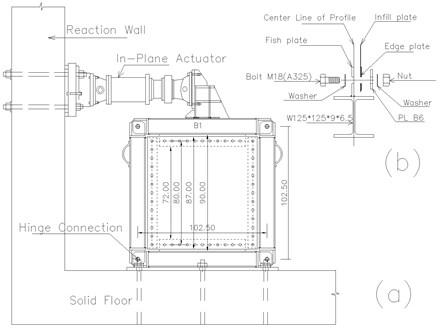
Five quarter-scale specimens were fabricated and prepared for a cyclic loading test (Fig. 1). Two of the specimens were unstiffened and fabricated from an aluminum sheet plate and a mild steel sheet plate. These specimens were named AL-SPSW and US-SPSW respectively. AL-SPSW is aimed to study the effect of different mechanical properties of infill plate. The three other specimens were stiffened steel plates of different stiffening configurations, i.e., cross-stiffened (CS-SPSW), circular-stiffened (CRS-SPSW), and diagonally stiffened (DS-SPSW). All the specimens had the same aspect ratio, which is equal to one. Each infill plate was connected to the boundary frame by 48 M18 A325 bolts. Its overall dimension was 87 cm with 80 cm center-to-center of connecting bolt holes (Fig. 2). All four edges were strengthened by 70 mm wide and 2.50 mm thick plate to prevent tearing at the edge of the walls due to bolt holes (Fig. 1). The cross-sectional area of all the stiffeners was 2.5×30 mm. The other specifications of specimens are given in Table 1.
Table 1Specification of test specimens
Specimens | Infill thickness (mm) | Stiffener thickness (mm) | Stiffeners pattern | Total weight (kg) | Infill plate dimension (mm) | Boundary frames |
AL-SPSW | 1.5 | – | – | 4.75 | 870×870 | W125×125×9×6.5 |
US-SPSW | 1.25 | – | – | 11.75 | ||
CS-SPSW | 1.25 | 2.5 | Cross | 14.0 | ||
CRS-SPSW | 1.25 | 2.5 | Circular | 13.85 | ||
DS-SPSW | 1.25 | 2.5 | Diagonal | 13.80 |
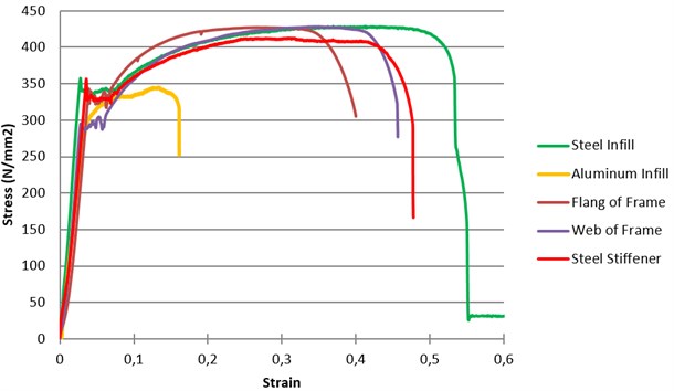
The thickness of each infill plate was based on the minimum available thickness at the test location for the steel and aluminum infill plates. For comparison, all the stiffened steel plates had the same thickness as the unstiffened infill plates. The three stiffened specimens (CS-SPSW, CRS-SPSW, and DS-SPSW) had the same total area of stiffeners. The stiffeners were connected to the infill plate with a fillet weld. The mechanical properties of the specimens were obtained by standard coupon tensile tests (Fig. 3), and these properties are summarized in Table 2. As can be seen in Fig. 3, the mechanical properties of the steel infill plate and stiffeners are in close range which is in different trend of the previous research. In most of the research the low yield point steel infill plate was strengthened by steel stiffeners. The rapture of the aluminum infill plate in the low strains is another notable behavior in the Fig. 3. One of the goals of the present research is to study the precision of the PFI method for low rapture materials.
Table 2Summary of tensile coupon test
Coupon | Member | Thickness (mm) | Elastic modulus (MPa) | Yield stress (2) (MPa) | Ultimate stress (3) (MPa) | Yield strength ratio = (2)/(3) (%) | Rapture strain (%) |
AL_Inf | Aluminum infill plate | 1.5 | 69 | 275.67 | 350 | 79 | 16 |
St_Inf | Steel infill plate | 1.2 | 200 | 350 | 430 | 81 | 53 |
St_FlangF | Flange of boundary frame | 9.0 | 200 | 320 | 427 | 75 | 40 |
St_WebF | Web of boundary frame | 6.0 | 200 | 288 | 427.9 | 67 | 45 |
St_Stiff | Stiffeners | 2.5 | 200 | 335 | 412.2 | 81 | 48 |
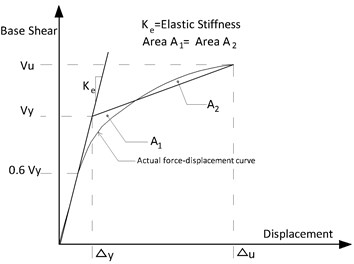
In the plane-frame integration method which is known as PFI method, neglecting the effect of flexural behavior (global bending stress), the shear load-displacement relation of SPSW is characterized [25]. The shear dominant behavior of SPSW is expected in the ductile SPSW with low number of stories. In such SPSWs, the shear load and displacement relation can be obtained separately and, by superimposing that results, the shear load-displacement diagram of the steel plate shear walls can be defined. In the case of the tested specimens, the hinged boundary frame does not contribute in tolerating of the applied lateral displacement therefore, the shear load-displacement relation of the infill plate defines the characterized behavior of the specimens. The typical characterized behavior of the infill plate based on the PFI method is shown in Fig. 4. In this figure the points C and D defines the buckling and yielding limits respectively and, the ultimate strength of the infill plate is equal to the yielding load. As shown in Fig. 4, for a infill plate of width b, height of d and thickness of , the buckling and yielding points are determined by equation 1 to 8:
where , , , , , are infill plate thickness, modules of elasticity, Poisson’s ratio, uniaxial yield stress, shear modules of material of infill plate and angle of inclination of tension filed respectively. , is the aspect ratio of the panel or subpanel, is the greater value between and . The critical shear stress, critical shear load, critical shear displacemet, shear strength, shear yielding displacement and shear stiffness are shown by , , , , symbols respectively. The symbol of denotes the yielding tension field and determined by Eq. (9):
The and are modification factor and the values of 0.8 1 and 1 1.7 proposed. Sabouri-Ghomi et. al. [25] for ductile steel plate walls with moment connection of beam-column, enough column rigidity and welded steel plate to boundary frame proposed the values of 1.0 and 1.2 for and respectively. Sabouri-Ghomi et. al. [25] concluded for specimen with SPSW with pin joints at the end of the beams 0.8 and 1.7 showed best fits of the results of PFI method with the test results of the Timler [26]. In the case of present research with hinged boundary frame, different material classification and bolted connection of infill plate to frame, the definition of proper values of and is the aim of the research.
A properly designed stiffener with adequate rigidity induces nodal lines in the stiffened plate. In such a plate, the overall buckling mode changes to subpanel local buckling, which is restricted by stiffeners. Thus, the elastic buckling strength of such a stiffened plate can be computed by considering an individual subpanel between the stiffeners, and the stiffened plate can be treated as a simply supported plate [18]. The optimum stiffener arrangement can prevent overall buckling; thus, the critical stress of the stiffened plate is equal to the critical stress of an individual simply supported subpanel. Meanwhile, for proper stiffened SPSW, steel plate should buckled after the infill plate yielding, therefore based on the PFI method the maximum critical stress of the (/) could be used for the calculation of the shear strength and yielding displacement of the infill plate by equation 4 and 5. This method was used for rectangular subpanels and the precision of such converting of the stiffened SPSW to the subpanels and its applicability for other pattern is a part of the present research. Drawn from AISC-820 [27] and the study of Alinia et al. [18], Eq. (10) was used to arrange the symmetrical stiffeners:
where is the thickness of the stiffeners, is the height of the stiffeners and x is the number of horizontal or vertical stiffeners. Eq. (11) and (12) were employed to comply with AISC-820 [27] and AISC-360 [28] and reduce the slenderness of the plate:
Fig. 1All infill plates: a) AL-SPSW, b) US-SPSW, c) CS-SPSW, d) CRS-SPSW and e) DS-SPSW
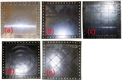
Fig. 2a) Specimen dimensions, b) connection of infill panel to the boundary frame
The stiffeners were designed to be shorter than the plate to prevent the direct transmission of the applied load. The cross-sectional areas of the stiffeners of the other stiffened specimens (CRS-SPSW, DS-SPSW) were the same as that of the CS-SPSWs, and only the configuration and pattern of the stiffeners were changed (Fig. 1).
3. Test description
A hinged boundary frame was used to reduce the complexity of the cyclic behavior of the SPSWs and the interaction of the infill plates with the frame. Furthermore, using such a frame is more economical than using a rigid connection frame. Each SPSW infill plate could be connected to the fish plate of the boundary frame by only a set of bolts; thus, new specimens could be replaced conveniently after each test. The frame consisted of four I-shaped profiles of 125×125×9×6.5 and high tensile plate, and these profiles were connected with M30 A325 bolts. The frame had a center-to-center distance of 102.5 cm, and the inner frame clear distance was 90 cm (Fig. 2). The fish plates with thickness of 6 millimeter were welded to the boundary frames. The fish plates beside to providing the connection of the infill plate, increase the rigidity of the boundary frame members.
Fig. 3Results of tensile test of coupons
A lateral support system was provided (Fig. 5) to ensure that all the specimens work ideally under cyclic displacement, without out-of-plane displacement. This system allows only for in-plane displacement of the specimens.
Lateral cyclic displacement was applied to the specimens with an actuator mounted between the frame and the reaction wall. A primary evaluation of the maximum available displacement was necessary because of the limitation of the actuator stroke. The yield displacement corresponding to the US-SPSW specimens was measured using the plate frame interaction (PFI) method [25], finite-element modeling, and the material properties obtained from the tensile testing of coupons (Fig. 2). The displacement history was calculated based on FEMA 461 [29], which is consistent with the ATC-24 protocol to a certain extent [30]. According to FEMA 461, at least six cycles must be executed at the lowest damage state. The displacement history is shown in Fig. 6. The specimens were loaded until the failure mode appeared or the actuator stroke reached its limitation.
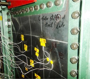
For data collection, the actuator displacements were recorded. In addition, two linear variable differential transformers (LVDTs) were employed to measure the exact displacement at the top of the specimens, in accordance with FEMA 461 [29]. To control slippage of the frame, a LVDT horizontally installed on the base plate. Several strain gauges were attached to the infill plates and frame members at various positions to record the strain and its changes during the test.
Fig. 4a) shear load-displacement of infill plate only according to b) PFI method and c) schematic of unstiffened and stiffened SPSW [25]
![a) shear load-displacement of infill plate only according to b) PFI method and c) schematic of unstiffened and stiffened SPSW [25]](https://static-01.extrica.com/articles/18472/18472-img4.jpg)
Fig. 5a) test setup and lateral support system, b) lateral support detail
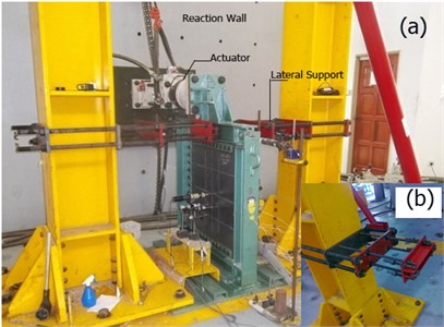
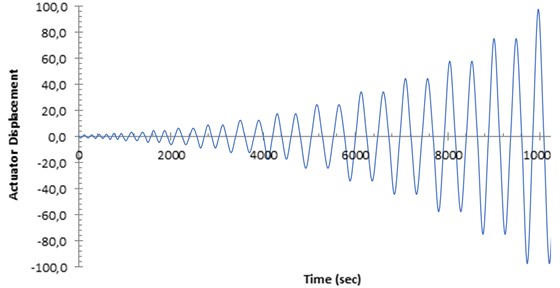
Fig. 6Displacement history of actuator
4. Results and discussion
4.1. Cyclic behavior and hysteretic response
Lateral shear displacement was applied to the top of specimens with a hydraulic actuator. The shear load and shear displacement were recorded during the tests. To trace the required data, several LDVTs and uniaxial strain gauges were installed at the proper positions. The values of 1.0and 1.7 were used for all specimens to draw the load-displacement according to the PFI method.
4.1.1. AL-SPSW specimen
Based on the data from the LVDTs and strain gauges, the buckling of the AL-SPSW infill plate started during cycle 5 at a displacement of 0.6 mm (0.069 % drift). Subsequently, several buckling sounds were heard, and they continued throughout the remainder of the test. The first tension field appeared during cycle 12 at a displacement of 4.47 mm (0.51 % drift). Furthermore, a very clear tension field action was observed during cycle 19 with a displacement of 16.9 mm (1.94 % drift). During cycle 23 at a displacement of 22.73 mm (2.61 % drift), the infill plate was torn in the top right corner of the infill plate, and tearing incidents in the bottom left and the top left followed. During cycle 25 at a displacement of 43.3 mm (4.69 % drift), the top left tearing was extended. Due to the joining of the abovementioned tearing during cycle 26, a sudden failure in the infill plate occurred, and loading was stopped.
By comparing the yielding displacement of the SPSWs obtained from the test and PFI method, the precision of the PFI method in the prediction of the yielding displacement of the specimens can be evaluated. The yielding displacement in the test can be acquired from strain gage data and idealized bilinear load-displacement curve of the tested specimens. The load-displacement curves of the test specimens were obtained (Fig. 8) by tracing the key points of hysteresis curves. The idealization method of the actual load-displacement curve is shown in Fig. 9.
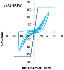
The strain-gauge readings showed that yielding occurred during cycle 23 at a displacement of 16.65 mm (1.92 % drift). The yielding displacement of the AL-SPSW according to PFI method was 10.8 millimeters. While based on the ideal bilinear load-displacement curve (Fig. 9), yielding displacement of AL-SPSW was occurred in displacement equal to 23.4 millimeters. As can be seen the strain-gauges and PFI data for yielding displacement are close together. The maximum load-carrying capacity of the specimen was 134.18 kN, which was reached at a displacement of 41.5 mm (4.78 % drift). The shear strength of the specimen predicted by PFI method was 166.5 kN. The hysteresis curve of the aluminum infill plate, AL-SPSW is shown in Fig. 7(a).
Table 3Comparison of test results and PFI method
Specimens | Buckling displacement (mm) | Buckling load (kN) | Yielding displacement (mm) | Yielding load (KN) | Ultimate load (kN) | Test maximum drift (%) | ||||||||||
PFI | Test | PFI | Test | PFI | Test | PFI | Test | PFI | Test | + | – | |||||
S.G. | + | – | + | – | + | – | ||||||||||
AL-SPSW | 0.1 | 0.60 | 3.9 | 0.89 | 10.8 | 16.65 | 27.5 | 23.4 | 166.5 | 104.1 | 97.1 | 166.54 | 134.18 | 125.46 | 5 | 5.2 |
US-SPSW | 0.067 | 2.26 | 6.6 | 4.57 | 4.60 | 12 | 30.4 | 29.6 | 174.9 | 137.1 | 121.4 | 174.9 | 185.23 | 171.9 | 9 | 8.8 |
CS-SPSW | A.Y. | 2.87 | A.Y. | 39 | 2.0 | 6.48 | 12.17 | 12.6 | 200.1 | 134.58 | 144.9 | 200.1 | 179 | 177 | 4.85 | 6.47 |
CRS-SPSW | × | 5.40 | × | 42.2 | × | 7.8 | 15.27 | 9.86 | × | 145.35 | 139.2 | × | 185 | 190 | 5.78 | 5.78 |
DS-SPSW | × | 12 | × | 69 | × | 7.3 | 14.2 | 13.45 | × | 134.2 | 137.1 | × | 167 | 165 | 5.59 | 6.47 |
+: Positive loading, -: Negative loading, A. Y.: After yielding, S.G. strain gauge data. | ||||||||||||||||
In Table 3, a comparison of the theoretical (PFI method) and experimental results is provided. In this table the test data for yielding displacement, yielding load and ultimate load were calculated based on the idealization of the load-displacement curve to the bilinear curve.
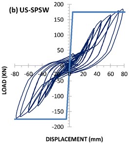
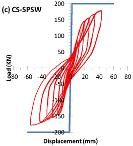
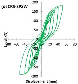
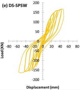
Fig. 7Hysteresis curve of specimens
4.1.2. US-SPSW specimen
In the US-SPSW specimen, buckling started during cycles 9 and 15 in the bottom half and at the center of the infill plate, respectively. The buckling during cycle 9 corresponded to displacement 2.26 mm (0.26 % drift). The first sound of pop-up buckling was heard during cycle 9 at a displacement of 2.5 mm (0.29 % drift). The first buckling wave of the tension field was observed during cycle 16 at a displacement of 6.66 mm (0.76 % drift). During cycle 19, with 17 mm displacement (1.95 % drift), a buckling line appeared in the top left corner and then in the top right corner.
The strain-gauge data showed that the first sign of infill-plate yielding occurred during cycle 15 at a displacement of 12 mm (1.38 % drift). The yielding displacement of the US-SPSW according to PFI method was 4.6 millimeters. Based on the ideal bilinear load-displacement curve (Fig. 9), yielding displacement of US-SPSW was occurred in displacement equal to 29.6 millimeters. The maximum load-carrying capacity of the specimen was 185.23 kN, which was reached at a displacement of 77.82 mm (8.94 % drift). The maximum displacement of the specimens was 78.16 mm. The hysteresis curve of the specimen for cyclic loading is shown in Fig. 7(b). A good agreement between the results of the test and the PFI method exists, as shown in Table 3. Furthermore, considerable variation found between the yielding displacement obtained based on the bilinear idealization of test data located and PFI data.
Fig. 8Load-Displacements curves of all specimens
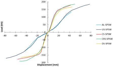
Fig. 9Idealization of load-displacement curve by bilinear
4.1.3. Specimen CS-SPSW
To prevent the buckling of the base plate at the free edges, two additional strong supports were installed on both sides of the base plate in the testing frame. The primary buckling occurred during the installation process in the top right corner developed during cycle 18 at a displacement of 4.875 mm (0.56 % drift). The subpanel below the first top right panel buckled during cycle 21. As shown in Fig. 10, the overall tension-field buckling of the infill plate was turned into the local buckling of the subpanels. The top left vertical stiffener buckled and yielded during cycle 20 at a displacement of 2.87 mm (0.32 % drift). The strain gauges reported that first sign of yielding of the infill plate appeared during cycle 11 at a displacement of 6.48 mm (0.74 % drift) whereas, by ideal bilinear load-displacement curve, the yielding displacement of 12.17 mm obtained.
The hysteresis curve of the specimen is shown in Fig. 7(c). The maximum load-carrying capacity of the CS-SPSW specimen was 179 kN, which was reached at a displacement of 42.2 mm (4.85 % drift). The maximum displacement of the specimen was 56.3 mm (6.47 % drift). A comparison of the PFI method and test results is shown in Table 3. The stiffeners situation could be one of the main reasons of the considerable difference between the PFI and test results. In the PFI method, it was assumed that all subpanel was stiffened at all four edges and they reached their ultimate yielding strength while, in the case of CS-SPSW, there are several subpanels that were stiffened in the three side. As a result, these three side stiffened subpanels couldn’t reach their yielding strength.
4.1.4. CRS-SPSW specimen
The welding of the stiffeners created a distortion in the infill plate. During the installation process of the infill plate on the boundary test frame, three primary buckling lines in the corners of the infill plate appeared. During cycle 17, the buckled lines located in the right half of the specimen (reaction wall on the right side) were slightly developed.
The LVDT installed at the center of infill plate showed a sudden increase in out-of-plane displacement during cycle 13 at the displacement of 5.4 mm (0.63 % drift). The higher strain and out-of-plane displacement were observed in the infill plate farthest from the center. The outer stiffeners were also subjected to a higher strain, especially along the diagonal direction.
The tension-field action is clearly very vital for dissipating more energy in the SPSWs. In the case of the CRS-SPSW specimen, the tension-field buckling waves appeared as a set of parallel rings between the stiffeners (Fig. 11). As shown in Fig. 7(d), which shows the hysteresis curve of CRS-SPSW, the hysteresis loop expanded and the capacity of the system to absorb more lateral displacement increased considerably because of this special kind of buckled rings during the last cycle (cycle 27). The maximum load-carrying capacity was 190 kN at a displacement of 51.4 mm (5.9 % drift), and the maximum displacement of the specimen was equal to 53 mm (6.1 % drift).
Fig. 10Local buckling of infill plate between the stiffeners for CS-SPSW
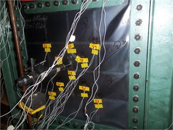
Fig. 11Buckling rings between the stiffeners for specimen CRS-SPSW
4.1.5. DS-SPSW specimen
Similar to the buckling in other specimens, the buckling in the DS-SPSW specimen started in the corners of infill plate. The first buckling line inside the subpanel developed during cycle 17 at a displacement of 12 mm (1.38 % drift). According to the LVDT data, all four central subpanels buckled during cycle 26 at 41.18 mm displacement (4.74 % drift). The installed strain gauges on the stiffeners showed that the stiffeners that do not pass across the center of the infill plate were suffering more strain. This behavior was even clearer after cycle 24 at a displacement of 41.2 mm (4.74 % drift). The buckling of these stiffeners also occurred during the same cycle.
During cycle 26, with a displacement of 48.5 mm (5.53 % drift), the yielding of the column as a singularity phenomenon occurred. Subsequently, the strain remained below the yielding strain. The specimens lasted 26 cycles (Fig. 7(e)), and the maximum load-carrying capacity was 165 kN at the 47.37 mm displacement (5.44 % drift). The maximum displacement of the specimen was 56.19 mm (6.47 % drift). The notable characteristic of the DS-SPSW specimen is the occurrence of nodal buckling, but the configuration of the stiffeners prevented the complete formation of tension fields between the stiffeners (Fig. 12).
Fig. 12Nodal buckling lines for DS-SPSW
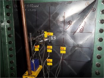
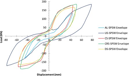
Fig. 13Envelope of hysteresis curves of all specimens
4.2. Comparison of cyclic behaviors
The envelopes of the hysteresis curves of all the specimens are shown in Fig. 13. Importantly, owing to the use of a hinged connection, the boundary frame did not contribute to the resistance of the applied lateral load, and only the infill plates suffered from the applied displacements. For two unstiffened infill plates (US-SPSW and AL-SPSW), the slopes of the hysteresis curves are smaller during the early loading cycles. In other words, the lateral stiffness of the system is negligible compared with the other parts of hysteresis curve. This behavior was reported in previous studies in which a hinged boundary frame or thin infill plates were used [31-34]. Pinched hysteresis loops are characteristic of thin SPSWs. In such panels, buckling occurs before yielding, and once the tension-field action is formed, their performances will be improved at high-amplitude displacements.
Compared with the unstiffened infill plates, all the stiffened specimens exhibited improved buckling behaviors, and the effect of this behavior were reflected in their hysteresis curves, which had larger initial slopes. Owing to their considerably enclosed areas, the stiffened panels displayed superior and wider hysteresis curves and absorbed more energy. Compared with the un-stiffened panels, the hysteresis loops of stiffened panels at the same time that are stable, had less displacement and no degradation. These advantages distinguished the cyclic behavior of the stiffened panels. No considerable differences found between the envelope of the stiffened specimens. As shown in Table 3, installation of stiffeners had a negligible impact on the ultimate strength of the specimens while, it influenced the buckling load and shear yielding displacements. Such effect of the stiffeners also confirmed by Alinia et al. [17] and Sabouri-Ghomi et al. [19].
4.3. Stiffness
The load–displacement curves of the test specimens were obtained (Fig. 8) by tracing the key points of their hysteresis curves. The elastic stiffness results are summarized in Table 4. The methodology for extracting the elastic linear stiffness is shown in Fig. 9. This method combines the ATC-40 [35] and FEMA440 [36] standards, and it is established based on equal energy definition. According to the equal energy curve definition, the enclosed areas under the load-displacement curve and the ideal bilinear curve should be equal. A comparison of the stiffness of the unstiffened steel plate with those of the other specimens indicated that the stiffeners significantly changed the shear stiffness, especially for the cross-stiffened specimen (CS-SPSW), whose stiffness increased up to 240 %.
Table 4Stiffness and ductility of the specimens
Specimens | Elastic Stiffness (kN/mm) | Ductility | ||||||
Relative to US-SPSW | Relative to US-SPSW | |||||||
+ | – | + | – | + | – | + | – | |
AL-SPSW | 3.79 | 4.16 | 0.84 | 1.01 | 1.41 | 1.34 | 0.62 | 0.58 |
US-SPSW | 4.5 | 4.1 | 1 | 1 | 2.29 | 2.32 | 1 | 1 |
CS-SPSW | 11.05 | 11.5 | 2.46 | 2.80 | 3.36 | 4.34 | 1.47 | 1.87 |
CRS-SPSW | 9.52 | 14.12 | 2.12 | 3.44 | 3.22 | 4.81 | 1.41 | 2.07 |
DS-SPSW | 9.45 | 10.2 | 2.10 | 2.48 | 2.99 | 3.69 | 1.30 | 1.59 |
+: Positive loading, -: Negative loading | ||||||||
Fig. 14 illustrates the stiffness performances of all the panels. Owing to their imperfections, the unstiffened panels (AL-SPSW and US-SPSW) exhibited early buckling after a few primary cycles, and this early buckling influenced their performances. This effect appeared as a decrease in stiffness up to a certain drift, and once the tension-field action initiated, the stiffness increased. The uncommon variation of the stiffness of AL-SPSW and US-SPSW in Fig. 14 could be related to the used hinged boundary frame that did not provide any lateral stiffness for the specimens. In the case of AL-SPSW and US-SPSW, the infill plate buckled at the beginning of the loading and the stiffness degradation started and it was continued until the tension field action started. After the emerging of the tension field, the stiffness of those specimens increased. The curves in Fig. 14 were drawn based on the real slope of the tangent line to the load–displacement curves in the key points.
Fig. 14Stiffness vs. Drift
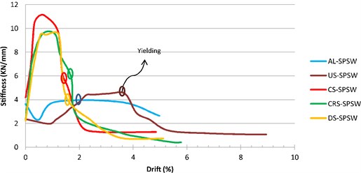
In Fig. 14, the horizontal parts correspond to the stiffness of the panels in the linear part of load-displacement curves. The effect of material type is clear from the stiffness of the unstiffened specimens. As shown in Fig. 14, AL-SPSW and US-SPSW obtained almost similar stiffness performances, but their corresponding yielding drifts were different. Referring to the Fig. 14, the stiffness variation of the CRS-SPSW and DS-SPSW were similar. The highest stiffness was obtained by CS-SPSW, but its stiffness degradation was unfavorable. The gradually decrease in the stiffness is considered as the favorable trend of stiffness degradation. For structures with stiffness degradation, the required ductility need to be considered in the design process. In addition, due to stiffness depredation, the stability of a structure need to be evaluated. The structures with gradual stiffness degradation, are able to redistribute the plastic deformation and provide a larger inelastic deformation. From this aspect, after yielding, the stiffness of DS-SPSW exhibits a better degradation trend, indicating that the panel with diagonal stiffeners performed better.
To cover any potential aspect of stiffness of the specimens, the hysteric stiffness degradation also can be diagnosed from the hysteresis loops. According to the FEMA [37] the hysteric stiffness degradation occurred when the slope of the hysteresis curve decreases during subsequent loops (Fig. 15(a)). Such behavior when accompanied by pinching in hysteresis curve will results a dramatic decrease of hysteric stiffness. Pinching behavior is characterized by large reduction in stiffness during reloading after unloading, along with stiffness recovery when displacement is imposed in the opposite direction (Fig. 15(b)).
Fig. 15a) hysteric stiffness degredation, b) pinching behavior in the reloading process [37]
![a) hysteric stiffness degredation, b) pinching behavior in the reloading process [37]](https://static-01.extrica.com/articles/18472/18472-img19.jpg)
![a) hysteric stiffness degredation, b) pinching behavior in the reloading process [37]](https://static-01.extrica.com/articles/18472/18472-img20.jpg)
As can be seen in Fig. 7(a) and 7(b), such behavior exactly can be distinguished for AL-SPSW and US-SPSW. In these unstiffened specimens, the hysteresis curves appeared as the sloped loops with a pinched curves due to the stiffness recovery in the reloading process. Considering the Figs. 7(c) to 7(e), the stiffness has improved the hysteric stiffness degredation meanwhile, the pinching effect has decreased. Among stiffened specimens, no fundamental differences found in the hysteric stiffness degredation but, CRS-SPSW appeared in superior level.
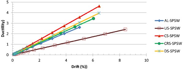
4.4. Ductility
The capacity of a structure to sustain deformations after its initial yielding, without any significant reduction in ultimate strength or occurrence of breakage, is defined as ductility. This factor indicates the capacity of a structure to absorb seismic energy through plastic deformation. Furthermore, ductility is one of the most important factors for predicting of the behavior of structures and their ultimate capacity under a lateral load. In terms of quantity and referring Fig. 9, displacement ductility is defined as the maximum displacement () divided by the first yield displacement Eq. (13). The overall ductility values of the panels are calculated based on the definition of the ideal bilinear load–displacement curves of the panels and summarized in Table 4:
The ductility gains at different levels of drift are shown in Fig. 16. All the stiffened specimens showed increased ductility, and CS-SPSW showed superior behavior over other stiffened panels. For stiffened specimens, it was found that stiffeners configuration has little effect on the ductility variation. In addition, circular stiffeners exhibited the lowest amount of the ductility increase among stiffened specimens. As stated earlier in clause 4.3, in the case of stiffness degredation of the structure, the required ductility increases. Specimen CS-SPSW showed a considerable stiffness degredation but its ductility could justify its superiority among another stiffeners configuration. Despite the failure of the aluminum panel during the early cycle of loading, its ductility was better than that of the unstiffened steel plate because of the lower yield stress of the former.
Fig. 16Ductility at different levels of drift
4.5. Energy dissipation
The area under the hysteresis curve is defined as the energy-dissipation capacity (Fig. 17). The formation of tension fields (Fig. 18), plastic buckling, and stable hysteresis loops were the key factors leading to the absorption of more energy in the SPSWs. The dissipated energy per cycle is plotted in Fig. 19. Notably, energy dissipation continued to increase with every cycle, except for AL-SPSW during the last cycles. In every subsequent pair of cycles with equal target displacements, the unstiffened panels (AL-SPSW and US-SPSW) absorbed less energy during their subsequent running cycles. By contrast, such a behavior is improved for stiffened panels, especially for DS-SPSW, which absorbed equal energy at the same running cycle amplitude. The relatively wide hysteresis loops enclosing considerably more area for stiffened panels indicated the relatively large energy-absorption capacity of the stiffened panels. As shown in Fig. 19, the performance of CRS-SPSW during the last cycle is distinct, as it dissipated a larger amount of energy compared with other panels.
Fig. 17Dissipated energy methodology of every hysteresis loop
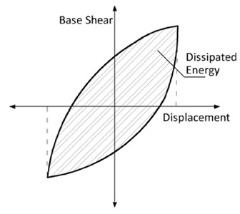
Fig. 18Different buckling mode for: a) AL-SPSW, b) US-SPSW, c) CS-SPSW and d) CRS-SPSW
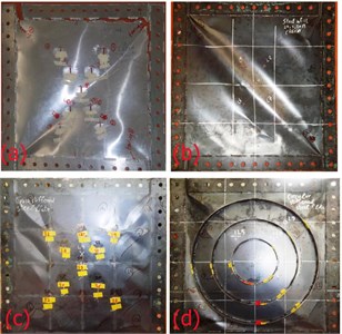
Fig. 19Dissipated energy per every cycle of all panels
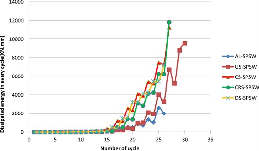
Fig. 20Dissipated energy by all specimens
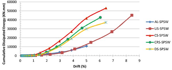
The cumulative dissipated energy is plotted against the drift in Fig. 20. As shown in the graph, among the stiffened panels, CS-SPSW absorbed the greatest amount of energy. Owing to the long cyclic life of the unstiffened steel panel (US-SPSW), its energy absorption seems to be satisfactory. Although the failure of the aluminum infill plate (AL-SPSW) occurred during the early cycles, its energy-dissipation capacity was similar to that of unstiffened steel infill plate.
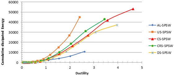
Fig. 21 shows another view of energy dissipation behavior. As shown in the figure, US-SPSW up to a ductility level of 2 seemed more effective in terms of energy dissipation than other panels. The aforementioned characteristic behavior of the unstiffened steel panel is advantageous when the gained ductility level is limited by design considerations. Up to a ductility level of 3.5, CRS-SPSW showed better performance in absorbing energy. The performance of AL-SPSW was not remarkable. Fig. 21 also shows the considerable differences between AL-SPSW and the other panels.
Fig. 21Ductility versus cumulative dissipated energy
5. Conclusions
The cyclic behavior of stiffened and unstiffened SPSWs was examined in this paper. Among the five test specimens, two were unstiffened plates (aluminum and steel), whereas the other three specimens were stiffened using cross, circular, and diagonal stiffeners on one side of the steel infill plate. The cross-sectional area of the stiffeners remained constant.
The tests showed that before yielding, the aluminum plate (AL-SPSW) exhibited good cyclic performance. However, owing to the material-hardening effect, it was unable to suffer more cycles, and brittle failure occurred. The PFI method for low elongation material (like Aluminum in the present research) found to owe estimate the shear strength of panel.
The unstiffened steel plate (US-SPSW) was very ductile, and exhibited a stable hysteresis curve. No tearing was observed in the specimen. The PFI method underestimated only 4.5 % of the shear capacity of this specimen, and its results exhibited a good agreement with the test results. The unstiffened steel plate possessed an excellent deformation capacity and it reached 9 % drift without any tearing. Owing to its excellent deformation capacity, its energy-dissipation performance was better after a 6.47 % drift.
The results of the stiffened specimens showed that the installation of stiffeners remarkably increased shear strength. The buckling mode was controlled by the stiffener configuration. The cross-stiffened specimen (CS-SPSW) showed the validity of the suggested equations applied in this study, with the overall buckling of the infill plate changed to the buckling of the subpanels with no major sign of the stiffeners buckling. The PFI method demonstrated an acceptable precision in predicting the ultimate strength of the cross-stiffened panels and overestimated the shear strength of CS-SPSW by only 10 %. The ultimate shear strengths of all the stiffened specimens were approximate; thus, by converting the circular-stiffened and diagonally stiffened panels to the ideal cross-stiffened pattern, their shear strengths can be estimated by the PFI method.
Compared with the unstiffened infill plates, all the stiffened specimens exhibited improved buckling behaviors. Owing to their significantly enclosed areas, the stiffened panels displayed a superior and wider hysteresis curve and absorbed more energy. The hysteresis loops of the stiffened panels, being simultaneously stable, had less displacement compared with the unstiffened panels, and no degradation was observed.
The stiffeners increased shear stiffness, energy dissipation, and ductility considerably, especially for the cross-stiffened specimen (CS-SPSW). The highest stiffness, dissipated energy, and ductility belonged to CS-SPSW, although its stiffness degradation was undesirable. After yielding, the stiffness of DS-SPSW exhibited a better degradation trend, indicating that the panel with diagonal stiffeners performed better. The stiffness of an unstiffened specimen was influenced by its material.
References
-
Berman J. W., Celik O. C., Bruneau M. Comparing hysteretic behavior of light-gauge steel plate shear walls and braced frames. Engineering Structures, Vol. 27, 2005, p. 475-485.
-
Berman J. W., Bruneau M. Experimental investigation of light-gauge steel plate shear walls. Journal of Structural Engineering, 2005, p. 259-267.
-
Guendel M., Hoffmeister B., Feldmann M. Experimental and numerical investigations on Steel Shear Walls for seismic retrofitting. Proceedings of the 8th International Conference on Structural Dynamics, 2011, Belgium, p. 474-481.
-
Vian D., Bruneau M. Steel Plate Shear Walls for Seismic Design and Retrofit of Building Structures. Ph.D. Dissertation in Civil, Structural, and Environmental Engineering, New York, 2005, p. 346.
-
Guneyisi E. M., Gulay A. A study on the seismic behavior of a retrofitted building based on nonlinear static and dynamic analyses. Earthquake Engineering and Engineering Vibration, Vol. 4, Issue 1, 2005, p. 173-180.
-
Vian D., et al. Special perforated steel plate shear walls with reduced beam section anchor beams. I: experimental investigation. Journal of Structural Engineering, 2009, p. 211-220.
-
Warn G. P., Bruneau M. Blast Resistance of Steel Plate Shear Walls Designed for Seismic Loading. Journal of Structural Engineering, 2009, p. 1222-1230.
-
Kharazi M. H. K., Ventura C. E., Prion H. G. L. Analysis and design of steel plate walls: experimental evaluation. Canadian Journal of Civil Engineering, Vol. 38, 2011, p. 60-70.
-
Kharrazi M. H. K., Ventura C. E., Prion H. Analysis and design of steel plate walls: analytical model. Canadian Journal of Civil Engineering, Vol. 38, 2011, p. 49-59.
-
Lanhui G., et al. Behavior of steel plate shear wall connected to frame beams only. International Journal of Steel Structures, Vol. 11, Issue 4, 2011, p. 467-479.
-
Khazaei Poul M., Nateghi Alahi F. Theoretical and numerical study on the strengthened steel plate shear walls by FRP laminates. IJE Transactions C: Aspects, Vol. 25, Issues 37-1, 2012, p. 25-37.
-
Clayton P. M. Pseudo-dynamic Testing of the Self-Centering Steel Plate Shear Wall. Steer, Civil and Environmental Engineering University of Washington, 2013.
-
Arabzadeh A., Soltani M., Ayazi A. Experimental investigation of composite shear walls under shear loadings. Thin-Walled Structures, Vol. 49, 2011, p. 842-854.
-
Zhao Q., Astaneh Asl A. Seismic behavior of composite shear wall systems and application of smart structures technology. Steel Structures, Vol. 7, 2007, p. 69-75.
-
Zhao Q., Astaneh Asl A. Cyclic behavior of traditional and innovative composite shear walls. Journal of Structural Engineering, 2004, p. 271-284.
-
Chen S. J., Jhang C. Cyclic behavior of low yield point steel shear walls. Thin-Walled Structures, Vol. 44, 2006, p. 730-738.
-
Alinia M. M., Dastfan M. Cyclic behaviour, deformability and rigidity of stiffened steel shear panels. Journal of Constructional Steel Research, Vol. 63, 2007, p. 554-563.
-
Alinia M. M., Sarraf Shirazi R. On the design of stiffeners in steel plate shear walls. Journal of Constructional Steel Research, Vol. 65, 2009, p. 2069-2077.
-
Sabouri Ghomi S., Sajjadi R. A. Experimental and theoretical studies of steel shear walls with and without stiffeners. Journal of Constructional Steel Research, Vol. 75, 2012, p. 152-159.
-
Sabouri Ghomi S., et al. Stiffness and strength degradation of steel shear walls having an arbitrarily-located opening. Journal of Constructional Steel Research, Vol. 79, 2012, p. 91-100.
-
Alavi E., Nateghi F. Experimental study of diagonally stiffened steel plate shear walls. Journal of Structural Engineering, Vol. 139, Issue 11, 2012.
-
Alavi E., Nateghi F. Experimental study on diagonally stiffened steel plate shear walls with central perforation. Journal of Constructional Steel Research, Vol. 89, 2013, p. 9-20.
-
Nie J. G., et al. Lateral resistance capacity of stiffened steel plate shear walls. Thin-Walled Structures, Vol. 67, 2013, p. 155-167.
-
Meng W., et al. Seismic behaviors of steel plate shear wall structures with construction details and materials. Journal of Constructional Steel Research, Vol. 107, 2015, p. 194-210.
-
Sabouri Ghomi S., Ventura C. E., Kharrazi M. H. K. Shear analysis and design of ductile steel plate walls. Journal of Structural Engineering, Vol. 131, Issue 6, 2005, p. 878-889.
-
Timler P. A. Experimental Study of Steel Plate Shear Walls (Structural Report No.114). Civil Engineering, Alberta, 1983, p. 112.
-
Sabelli R., Bruneau M. (AISC 820-06) Steel Design Guide- Steel Plate Shear Walls. A.I.S.C., American Institute of Steel Construction, 2007.
-
Specification for Structural Steel Buildings. ANSI/AISC 360-10, Chicago, Illinois, 2010.
-
Interim Testing Protocols for Determining the Seismic Performance Characteristics of Structural and Nonstructural Component in FEMA 461. Applied Technology Council, California, 2007.
-
Guidline for Cyclic Seismic Testing of components of steel Structures (ATC 24). Applied Technology Council, CA, 1992.
-
Tromposch E. W. Cyclic and Static Behaviour of Thin Panel Steel Plate Shear Walls. Master Thesis, in Civil Engineering, Alberta, 1987, p. 161.
-
Roberts T. M., Sabouri Ghomi S. Hysteretic characteristics of unstiffened perforated steel plate shear panels. Thin-Walled Structures, Vol. 14, Issue 2, 1992, p. 139-151.
-
Veladi H., Armaghani A., Davaran A. Experimental investigation on cyclic behavior of steel shear walls. Asian Journal of Civil Engineering, Vol. 8, Issue 1, 2007, p. 63-75.
-
Valizadeh H., Sheidaii M., Showkati H. Experimental investigation on cyclic behavior of perforated steel plate shear walls. Journal of Constructional Steel Research, Vol. 70, 2012, p. 308-316.
-
Seismic Evaluation and Retrifit of Concrete Buildings. Volume 1, ATC-40, Seismic Safety Commision, California, 1996, p. 346.
-
Improvement of Nonlinear Static Seismic Analysis Procedures. FEMA 440, Applied Technology Council (ATC-55 Project), California, 2005.
-
Effects of Strength and Stiffness Degradation on Seismic Response. FEMA P440A, Applied Technology Council, California, 2009.
Cited by
About this article

