Abstract
To realize the high efficiency mirror surface grinding of hard brittle materials (such as nano-ceramic material), this work firstly constructs an experimental platform for workpiece ultrasonic vibration and ELID combined plane grinding according to the processing mechanism of ultrasonic vibration assisted grinding and ELID grinding; then, based on the removal mechanism of hard brittle material, this work analyzes the kinematics of single abrasive grit with workpiece ultrasonic vibration plane grinding, and studies the effect of ELID plane grinding on the grinding depth; finally, based on the above work, this work proposes the mathematical model of material removal rate for the workpiece ultrasonic vibration and ELID combined plane grinding. Experimental results show that the material removal rate of combined plane grinding increases with the increase of the cutting depth and workpiece speed, the material removal rate of ultrasonic vibration and ELID combined grinding is higher than that of ELID grinding under the same conditions.
1. Introduction
Nano-ceramic materials have many advantages, such as high hardness, high strength, high temperature resistance, strong wear resistance, strong corrosion resistance, good insulation, and good chemical stability and so on, and have been applied in many fields such as aerospace, materials engineering, electronic engineering, chemical engineering and mechanical engineering. Nano-ceramic materials are hard and brittle, what also makes many disadvantages, such as high brittleness, low toughness and poor machinability. Although nano-ceramic materials can be processed by the ultra-precision machining technology, the theoretical basis of research on ultra-precision machining of the hard and brittle material technology in China is relatively weak. It is still a long process from industrialization [1-3].
At present, the ultrasonic vibration precision grinding and ELID (electrolytic in-process dressing) mirror grinding technologies are relatively mature technologies to high precision mirror grinding for the hard and brittle materials because of its high processing efficiency and wide application range. Ultrasonic vibration precision grinding combines ultrasonic vibration with ordinary grinding. The application of ultrasonic vibration can get a high precision surface and high removal of materials [4-6]. The ELID mirror grinding technology can be used to realize the combination of the electrolytic dressing and polishing of the grinding wheel. By using fine and micro abrasive particles, the micro machined surface with low roughness can be obtained and be applied for the continuous processing of the super mirror [7-9]. Two kinds of grinding methods have their own shortcomings, but they can be complementary in both advantages and disadvantages. Therefore, the combination of ELID grinding and ultrasonic grinding has become one of the important trends in the future [10].
Currently, to the best our knowledge, there are few reports on the combination of ultrasonic vibration grinding and ELID grinding technologies. You et al. [11] have adopted ultrasonic vibration and ELID composite grinding of carbon steel, and concluded that the surface roughness in a certain range is almost not affected by the influence of the grinding depth; however, they do not carry out a further research on the material conditions of the composite grinding removal mechanism. In our work, we combine the ultrasonic vibration grinding with ELID grinding and form a more efficient process of composite grinding technology. We also apply the ELID electrolysis principle and ultrasonic vibration grinding principle into the grinding removal process of nano-ceramic materials, and try to establish a mathematical model of material removal rate in composite grinding and test. This research work has obtained better research results.
This paper is structured as follows: Section 2 introduces the processing method of ultrasonic vibration and ELID composite plane grinding; Section 3 presents the material removal model of ultrasonic vibration and ELID composite plane grinding; Section 4 presents the experimental results; finally, the conclusion of this work is presented.
2. Processing method of ultrasonic vibration and ELID composite plane grinding
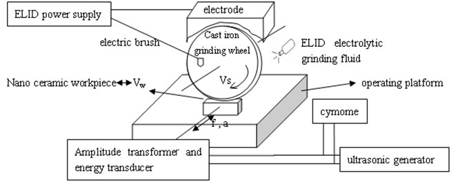
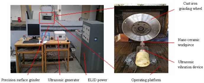
Ultrasonic vibration and ELID composite plane grinding based on the ultrasonic vibration of a nano-ceramic workpiece is shown in Fig. 1. On the precision surface grinder, the experimental platform of the one-dimensional ultrasonic vibration grinding system has been completed, and the plane ELID grinding device has been added [12]. The processing method of the ultrasonic vibration and ELID composite grinding imposes ultrasonic vibration on the workpiece materials along the axis of the grinding wheel, and the accomplishment of the electrolytic in-process dressing of cast iron grinding wheel can both give full play to the high removal of ultrasonic vibration grinding, and can show the advantages of the electrolytic wheel in-process dressing during the process of ELID ultra precision grinding, so as to realize the efficient mirror grinding of the workpiece material.
Fig. 1System diagram of ultrasonic vibration and ELID composite plane grinding
3. Material removal model of ultrasonic vibration and ELID composite plane grinding
3.1. Material removal mechanism of single abrasive particle ultrasonic vibration grinding
According to the removal mechanism of ceramic materials, there is a critical depth of cut , that is, when the cutting depth satisfies , the workpiece material has mainly plastic deformation; when the cutting depth satisfies , the workpiece material has mainly brittle rupture [13]. So, the cross section area of a single abrasive particle and workpiece could be calculated by Eq. (1) [14]:
where indicates abrasive cone semi-angle, and are the dimensionless constants, indicates the load; indicates the static fracture toughness of materials, presents the material stiffness. Axial ultrasonic vibration assisted grinding of single abrasive particle trajectory [15] is shown in Fig. 2.
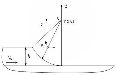
Fig. 3 shows a single abrasive particle cutting model of axial ultrasonic vibration grinding [16].
Fig. 2Diagram of axial ultrasonic vibration grinding and its single abrasive particle moving track
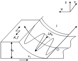
Fig. 3Single abrasive particle cutting model of axial ultrasonic vibration grinding
Considering the direction of rotation of the grinding wheel and the feed speed of the workpiece, the equation of motion of a single particle can be defined by Eq. (2):
where indicates the wheel peripheral speed, presents the workpiece velocity, is the emery wheel diameter, is the amplitude of ultrasonic vibration, is the ultrasonic vibration frequency, indicates the phase angle.
The velocity equation of single abrasive particle in axial ultrasonic vibration can be calculated by Eq. (3):
For ordinary grinding, the moving arc length of a single abrasive particle can be calculated by Eq. (4):
And the moving arc length of single abrasive particle in axial ultrasonic vibration can be obtained by Eq. (5):
Based on the above results, the volume of single abrasive particle removal material is defined by Eq. (6):
3.2. Grinding depth of ELID plane grinding
A cast iron grinding wheel is used as the anode to generate a chemical reaction, according to the principle of the electrochemical reaction, the quality of anodic corrosion is calculated by Eq. (7), and the anodic dissolution thickness is calculated by Eq. (8):
where indicates the quality of anodic corrosion, is the current efficiency, is the amount of metal-bonded atoms, is the electrode current, presents the electrolyzing time, is the ionic charge number, is the Faraday constant, indicates the anodic dissolution thickness, indicates the anode material density, is the effective area of anode.
The total resistance in the ELID grinding is determined by the oxide film resistance and the electrolyte resistance , there is a relationship between the thickness of the oxide film and the inter-electrode gap in the grinding process. The relationship between and is defined by Eq. (9):
where indicates the effective area of the cathode; is the resistivity of oxide film; represents the electrolyte resistivity.
According to the Ohm’s law, the electrode current can be calculated by Eq. (10):
then, the thickness of anodic dissolution can be calculated by Eq. (11):
Based on the above results, the actual grinding depth can be calculated by Eq. (12):
where, indicates the nominal grinding depth.
3.3. Material removal model of ultrasonic ELID composite plane grinding
Abrasive number of per-unit area of grinding wheel can be obtained by Eq. (13) [17]:
where indicates the abrasive grain volume ratio; indicates the single particle diameter.
In the unit time, the number of effective abrasive particles in the composite grinding area is defined by Eq. (14):
where indicates the wheel diameter width.
Based on Eqs. (6), (12) and (14), the axial ultrasonic vibration and ELID composite plane grinding material removal model is defined by Eq. (15):
3.4. Analysis of material removal model of ultrasonic ELID composite plane grinding
The material removal rate of ultrasonic vibration and ELID composite plane grinding is related to the way of material removal. The relationship between the actual cutting depth and the critical cutting depth defines the variation of the material plasticity or material brittleness. The material removal rate is also related to the material properties, ultrasonic vibration parameters, ELID parameters and grinding parameters. It increases with the increasing of ultrasonic vibration frequency parameters, grinding depth parameters, and wheel speed parameters, and decreases with the increasing of the material toughness, electrolytic voltage and oxide film thickness.
Ultrasonic vibration changed the trajectory of the abrasive particles, so that the trajectory length of abrasive particles becomes longer, and improves the material removal efficiency. Under the same condition, the relationship between the amount of removed material , when the axial ultrasonic vibration is not attached, and the amount of removed material , when the axial ultrasonic vibration is attached, can be defined by Eq. (16):
According to Eq. (16) it can be found that, with the increase of the thickness of the oxide film, the actual grinding depth also increases, what is beneficial to the removal of the workpiece material. However, when the thickness of the oxide film increases to the degree which surpasses the maximum diameter of the abrasive particles, then all the abrasive particles on the surface of the grinding wheel will be covered by oxide film, at this time, the abrasive particles will no longer have the ability to remove material, but they will play the role of grinding and polishing. Therefore, the thickness of the oxide film must be well controlled in the process of ultrasonic vibration and ELID composite plane grinding.
4. High efficiency removal test of ultrasonic vibration and ELID composite plane grinding
4.1. Test conditions
In this experiment, set the accuracy of 0.0001 g precision analytical balance as shown in Fig. 4, measure and calculate the material removal quality of the grinding specimen under the grinding parameters which are set in advance (grinding time is 3 minutes), get the average results of 3 experiments with the same grinding parameters, and then calculate the removal rate of the workpiece material.
Fig. 4Removal rate of measuring device
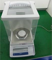
Table 1Experimental conditions
Parameter | Experimental condition |
Diamond grinding wheel | Iron-based metal matrix; Grain size W40; concentration 100 % |
Grinding wheel speed | 22.6 m/s |
Speed of table | 0.15 m/s, 0.2 m/s, 0.25 m/s, 0.3 m/s |
Workpiece | Nano-Al2O3 ceramics (15 mm×15 mm×7 mm) |
Grinding depth | 3 μm/pass, 4 μm/pass, 5 μm/pass, 6 μm/pass |
Grinding fluid | ELID solution and distilled water 1:50 configuration |
Ultrasonic vibration parameters | Frequency: 20 KHz; Amplitude: 13 μm |
After each grinding processing is completed, wash the specimen with acetone before the first weighing, remove abrasive dust and other impurities from the workpiece surface and then dry it for about 30 minutes to clear up with acetone. Experimental conditions are presented in Table 1.
This experiment aims at analyzing the influence of composite grinding parameters on the material removal rate. It chooses GOTEN GTS- 6016AHD precision surface grinder which is produced by Okamoto. It replaces the grinding wheel on the precision surface grinder with a ELID plane grinding device and attaches ultrasonic vibration to the workpiece material. The test site is shown at Fig. 5.
Fig. 5Experimental field device
4.2. Effect of table speed on material removal rate
The effect of table speed on the material removal rate is also tested in the grinding process, the duty cycle is 50 %, and the grinding depth is 5 μm. The experimental results are presented in Fig. 6, where the horizontal ordinate axis shows the speed of table, and the longitudinal ordinate axis shows the material removal rate. From Fig. 6, we can find the influence of table speed on the material removal rate under the condition of ultrasonic vibration and ELID composite plane grinding and ELID plane grinding. It also can be found that the material removal rates increase significantly with the increasing of table speed in two grinding methods. When the table speed improved, the speed of the wheel cutting into workpiece also improved, the effective abrasive particles through the grinding area grew in number, the fiction, impact and cutting between the oxide film and the surface of the workpiece enhanced the amount of removing workpiece material increased.
Fig. 6Effect of table speed on material removal rate
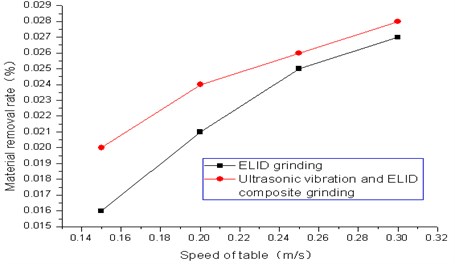
In this experiment, we also found that, when the other grinding parameters remain unchanged, and the table speed is changed, the material removal rate of ultrasonic vibration and ELID composite plane grinding is higher than that of the ELID plane grinding. In addition, when the table speed is lower, ultrasonic vibration has a bigger effect on the composite grinding. When the table speed is 0.15 m/s, the material removal rate of the ELID plane grinding is 0.016 %, while the material removal rate of ultrasonic vibration and ELID composite plane grinding is 0.020 %. When the table speed is 0.3 m/s, the material removal rate of these two grinding methods is close to 0.028 %, the material removal rate of ultrasonic vibration and ELID composite plane grinding is slightly higher. With the application of ultrasonic vibration, the contact arc length between the abrasive particles and workpiece becomes longer, and the plastic removal grinding area becomes larger. The pumping and eddy current applications with ultrasonic vibration are convenient for the grinding fluid to enter the grinding area, what can reduce the temperature of the grinding area, and cannot cause the high temperature carbonization of the abrasive particles, it is more favorable to the removal of workpiece material. To a certain extent, the impact and softening of ultrasonic vibration can reduce the hardness and plastic deformation resistance of workpiece material as well, the materials are easier to be removed. The application of ultrasonic vibration can further improve the self-sharpening capability of the grinding wheel, make the blunt abrasive particles fall off more easily and make new abrasive particles participate in the grinding area, improving the grinding performance. The cavitation of ultrasonic vibration can remove chips in time, reduce the blockage of the grinding wheel and improve the material removal rate.
4.3. Effect of grinding depth on material removal rate
Fig. 7 shows the influence of the grinding depth on the material removal rate under the condition of ultrasonic vibration and ELID composite plane grinding and ELID plane grinding, where the horizontal ordinate axis shows the grinding depth, the longitudinal ordinate axis shows the material removal rate. In the grinding process, the duty cycle is 50 %, and the table speed is 0.3 m/s.
Fig. 7Effect of grinding depth on material removal rate
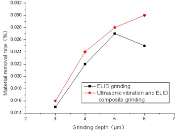
From Fig. 7, we can find that with the increase of grinding depth, the actual grinding thickness of single abrasive particle is increased, and the removal volume of single abrasive particle becomes larger. In this way, the removal rates under these two grinding methods go up with the increase of the grinding depth. When the grinding depth is small, the material removal rate of two grinding methods is close to 0.015 %, with the increase of the grinding depth, when the grinding depth is 5 μm, the material removal rate of two grinding methods is close to 0.028 %. When the grinding depth becomes small, the gap between ultrasonic vibration and ELID composite plane grinding and ELID plane grinding material removal rate is not very large, and the efficient removal of ultrasonic vibration does not play any role. However, with the increase of the grinding depth, the ELID plane grinding is not enough to remove the material required by the current grinding parameters, and the function of ultrasonic vibration becomes increasingly obvious. When the grinding depth is 6 μm, the material removal rate of ELID plane grinding is reduced to only 0.025 %, and the material removal rate of ultrasonic vibration and ELID composite plane grinding keeps increasing up to 0.030 %. The ELID plane grinding is a kind of precision and ultra precision grinding, not suitable for a large grinding depth. A larger grinding depth in the ELID plane grinding process will make abrasive particles on the outer layer of the wheel wear rapidly and fall quickly, and the new sharp abrasive particles have not enough time to be used in the workpiece material. So, the actual removal rate decreases significantly. For ultrasonic vibration and ELID composite plane grinding, the workpiece material is softened to a certain extent, and the grinding depth becomes larger, the ultrasonic vibration can play a greater role.
5. Conclusions
Based on the study of ultrasonic vibration grinding of single abrasive particle material removal volume and the characteristics of ultrasonic vibration and ELID composite plane grinding, considering the influence of ELID surface grinding on the grinding depth, the ultrasonic vibration and ELID composite plane grinding material removal models were established by the authors. The material removal rate is related to the way of material removal, and the way to remove the material depends on the relationship between the actual cutting depth and the critical cutting depth. The material removal rate is also closely related to the essence of material properties, material removal process, ultrasonic vibration parameters, ELID parameters and grinding parameters. Additional axial ultrasonic vibration can improve the grinding material removal rate in some degree. The material removal rates both in ultrasonic vibration and ELID composite plane grinding and ELID plane grinding increase with the increasing of workpiece speed. The material removal rate of ultrasonic vibration and ELID composite plane grinding is better than that of ELID plane grinding, and when the table speed is smaller than 0.15 m/s, the material removal rate of ultrasonic vibration and ELID composite plane grinding is up to 0.020 %, ultrasonic vibration has a bigger auxiliary effect on composite grinding. When the grinding depth becomes small, the material removal rates both in ultrasonic vibration and ELID composite plane grinding and ELID plane grinding increase with the increasing of the grinding depth. But, when the grinding depth increases to a certain extent, the effect of ultrasonic vibration can still improve the material removal rate. When the grinding depth is 6 μm, the material removal rate of ELID plane grinding is reduced to only 0.025 %, and the material removal rate of ultrasonic vibration and ELID composite plane grinding keep increasing up to 0.030 %. Under the same conditions, the material removal rate of ultrasonic vibration and ELID composite plane grinding is much higher than that of ELID plane grinding.
References
-
Yuan J. L., Zhang F. H., Dai Y. F. Development research of science and technologies in ultra-precision machining field. Journal of Mechanical Engineering, Vol. 46, Issue 15, 2010, p. 161-177.
-
Lee E. S., Won J. K., Chun Y. J. Ultra-precision lapping of machinable ceramic Si3N4-BN by in-process electrolytic dressing. International Journal of Advanced Manufacturing Technology, Vol. 31, Issues 11-12, 2007, p. 1101-1108.
-
Shao S. J., Zhao B., Li Y. Experimental research on the ultrasonic grinding surface topography of engineering ceramics. Applied Mechanics and Materials, Vols. 143-144, 2012, p. 411-415.
-
Zhao B., Zhao C. Y., Du B. Y. Experimental study on damage mechanism of nano-ceramic surface/subsurface under ultrasonic vibration aided grinding. Solid State Phenomena, Vol. 175, 2011, p. 107-111.
-
Liang Z. Q. Status and progress of ultrasonic assisted grinding technique. Acta Armamentarii, Vol. 31, Issue 11, 2010, p. 1530-1535.
-
Shao S. J., Zhao B. Surface quality of nano-ceramics by ultrasonic vibration grinding. Ordnance Material Science and Engineering, Vol. 37, Issue 2, 2014, p. 1-4.
-
Ohmori H., Lin W., Katahir Ai K. Developmental history and variation of precision and efficient machining assisted with electrolytic process principle and applications. The 1st International ELID-Grinding Conference, 2008.
-
Kuai J. C., Zhang F. H., Zhang Y. Research on minimum mechanism of roughness of ELID grinding. Advanced Materials Research, Vol. 135, 2010, p. 441-446.
-
Zhang H. L., Kuai J. C., Zhang F. H. Modeling of thickness of the oxide film in ELID grinding. Advanced Materials Research, Vol. 135, 2010, p. 376-381.
-
Yin S. H., Zeng X. L., Fan Y. F. Research progress of ELID mirror grinding technology. Chinese Journal of Mechanical Engineering, Vol. 21, Issue 6, 2010, p. 750-754.
-
You X. Z. Application of ELID and vibratory machining on the analysis and planning of precision grinding processes. National Taiwan Ocean University, Taiwan, 2003, p. 34-63.
-
Shao S. J., Zhao Bo, Bian P. Y. Study on the oxide layer characteristics of workpiece ultrasonic vibration and ELID composite plane grinding based on the ultrasonic vibration of nano-ceramics workpiece. Journal of Synthetic Crystal, Vol. 45, Issue 1, 2016, p. 217-223.
-
Marshall D. B., Lawn B. R., Evans A. G. Elastic/plastic indentation damage in ceramics: the lateral crack system. Journal of American Ceramic Society, Vol. 65, Issue 11, 1982, p. 561-566.
-
Bifano T. G., Dow T. A., Scattergood R. O. Ductile-regime grinding: a new technology for machining brittle materials. Journal of Engineering for Industry, Vol. 113, Issue 2, 1991, p. 184-189.
-
Zhang H. L. Ultrasonic Vibration Assisted Grinding Technology and Its Mechanism. Shandong University, Jinan, 2007, p. 15-37.
-
Lang X. J. Study on Grinding Force Modeling of Axial Ultrasonic Vibration Assisted Grinding. Central South University, Changsha, 2014, p. 11-20.
-
Zhang J. H. Study on Prediction of Grind-hardened Layer and Its Friction and Wear Performance. Shandong University, Jinan, 2008, p. 33-48.
About this article

This work was supported by the Doctoral foundation of the Henan Polytechnic University (Contract No. B2017-35), China.
