Abstract
This paper proposes a novel design torsional vibration isolator with negative stiffness structures. It consists of two shafts that are linked by positive springs and negative stiffness structures. The connection position of the two shafts has been designed into disc structure, which is the installation position of the positive springs and negative stiffness structures. The task of positive springs is to transmit the designed torque. In this paper, the nonlinear stiffness characteristics of the isolator are presented. The nonlinear mathematical model is presented, and its dynamic behaviors are investigated using the averaging method, and compared with that of the corresponding linear torsion isolator without negative stiffness structures. The study shows that the torsion isolator has a wider isolation region than that of the linear isolator. Furthermore, the performance of the isolator is sensitive to the damping of the system and the amplitude of vibration excitation. Choosing a suitable damping and vibration environment will be important for the stable application of this isolator.
Highlights
- A novel design torsional vibration isolator with negative stiffness structures is proposed
- The nonlinear dynamic model is proposed, and solved by averaging method
- Nonlinear torsional stiffness and vibration isolation characteristics of this novel isolator are studied
1. Introduction
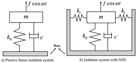
Traditional passive linear isolators have been studied in depth for a long time. A mass supported by a linear spring of stiffness on a rigid foundation is the typical system of passive linear isolator as shown in Fig. 1(a). This isolator can attenuate vibration only when the excitation frequency is greater than times of the natural frequency , where is the natural frequency of the system. This reveals that it is necessary to decrease the natural frequency of the system to widening the isolated vibration region. In the designed system, as the weight of the load is constant, the selection of a small stiffness becomes an effective method for decreasing the natural frequency. However, a low static stiffness causes a low load bearing capacity and a large static deflection, and even lead to instability. Many measures and structures have been studied to overcome this problem. In recent years, negative stiffness structure (NSS) and negative stiffness mechanisms have been studied as a means to improve the vibration suppression of passive vibration isolators [1]. Fig. 1(b) displays a typical isolator with NSS. NSS has been used to obtain a high static stiffness and small dynamic stiffness, which results in a low natural frequency [2]. By balancing the positive and the negative stiffness, and choosing the system parameters carefully, it is possible to achieve an isolator with zero dynamic stiffness at the static station, so-called quasi-zero-stiffness (QZS) isolator.
Studies on various isolators with NSS have attracted the interest of many researchers in recent years, and many results have been published ranging from design and theoretical analyses to experimental studies.
In design aspect, there are many works have been studied. Araki et al. [3] designed a quasi-zero-stiffness vibration isolator applying newly developed superelastic Cu-Al-Mn shape memory alloy bars, and obtained a vibration isolation system with large loading capacity. Liu et al. [4] introduced a QZS isolator using Euler buckled beam as the negative stiffness corrector, and studied its nonlinear dynamic characteristics. The results demonstrate that the proposed zero dynamic stiffness nonlinear isolator can outperform the equivalent linear one for certain frequencies, and the performance is related to the magnitude of the excitation amplitude. Niu et al. [5] designed a QZS vibration isolator using a slotted conical disk spring as NSS and investigated the vibration isolation performance theoretically. In the last few years, multi-degree of freedom QZS isolation systems have also been studied by researchers. Lu et al. [6] studied the vibration isolation performance of a two-stage vibration isolation system that has a geometrically nonlinear negative stiffness. A multi-direction scissor-like structural vibration isolator with QZS was designed by Sun and Jing to solve some engineering application difficulties [7]. In addition, Gatti et al. [8] studied a two degree-of-freedom system consisting of a linear and a nonlinear QZS oscillator. Furthermore, wang et al. [9] made a comparative study of nonlinear one and two degree-of-freedom vibration isolators with NSS. Zhu et al. [10] presented a novel design of a six degree of freedom vibration isolator, which applies magnetic levitation as the payload support mechanism. This system realizes inherent QZS levitation in the vertical direction, and zero stiffness in the other five degree-of-freedom.
Fig. 1Original principle model of vertical vibration isolation system
In the aspect of theoretical research, Yang et al. [11] introduced a nonlinear vibration isolation system with a negative stiffness mechanism and analyzed the isolation performance based on power flow theory. The dynamic characteristics of the isolation system with NSS have also been studied considering the stiffness and load imperfections. Huang et al. [12, 13] and Liu et al. [14] studied the dynamic responses of the isolation system considering the combined effect of load imperfection, stiffness imperfection, and excitation amplitude. Abolfathi et al. [15] studied the effects of mistuning a force-excited system containing a QZS vibration isolator. They also studied the dynamic characteristics of nonlinear vibration isolators with asymmetric stiffness [16]. Meanwhile, it is important to improve the system to achieve much better isolation performance and stability considering that the inherent nonlinearity of the isolation system could induce the jump phenomenon at around the resonant frequency. To receive stable dynamic characteristics and beneficial isolation performance, Sun et al. [17] proposed a QZS vibration isolator with time-delayed linear displacement active control, and studied the potential beneficial performance of this isolator. The stability and dynamic analysis showed that the time-delayed active control can not only further strengthen the robustness of the system stability, but also noticeably improve system transmissibility performance in both the force and base excitations and clearly decrease the settling time of the system transient response subject to an impact load. Furthermore, Wang et al. [18] analyzed a nonlinear isolator with NSS using the time-delayed cubic velocity feedback control strategy. The results indicated that their method could not only achieve a better isolation performance around the resonant frequency band, but also a better performance in the high frequency band where isolation is required.
In addition to the design and theoretical analysis of the isolation with NSS, some experimental and applied studies on nonlinear vibration isolators with NSS have also been reported in recent years. Zheng et al. [19] studied a high-static-low-dynamic stiffness isolator using a negative stiffness magnetic spring, the experimental results demonstrate that the negative stiffness magnetic spring can reduce the resonance frequency of the isolator. Xu et al. [20, 21] proposed a simple QZS isolation model consisting of four oblique linear springs and one vertical linear spring. The performance of the QZS system was verified through a series of experimental studies showing that the new model greatly outperforms standard linear isolation systems especially in the low-frequency domain. Li et al. [22] presented a vibration isolator using a magnetic spring combined with rubber membranes to obtain a low resonance frequency and provided an efficient method to construct a negative stiffness vibration isolator for practical applications. Le et al. [23] investigated and proposed a vibration isolation system with an NSS for driver seats in low frequency vibration conditions. From the experimental results, it was confirmed that the proposed system offers a larger isolation frequency range and higher attenuation rate than that of the system without NSS.
As mentioned above, the NSS plays a good role in the attenuation of the low frequency vibration. However, the existing researches on the NSS are mostly concentrated in the attenuation of translational vibration. In aspects of torsional vibration attenuation, in order to isolate the low frequency torsional vibration, according to the authors understand, there was only Zhou et al. [24] proposed a novel QZS isolator for torsional vibration, in which the NSS are offered by the cam-roller mechanism.
In this paper, a torsional isolator using connecting bar-spring mechanism as NSS is proposed. It is developed based on the design concept of an isolator in a previous work of the main authors of this paper [25]. The proposed isolator is a system in which the positive springs and NSS are connected in parallel. The purpose of the positive stiffness springs is to transmit the designed drive torque, and the isolation system can isolate the wide frequency band torsional vibration by paralleling the NSS. The study covers the static and dynamic characteristics of this torsional isolator with NSS. The nonlinear restoring torque equation is deduced by structural design of the isolator, then the nonlinear stiffness characteristics of the torsional vibration isolation system is studied. The vibration responses and isolation characteristics of the isolation system are studied by solving the dynamic equation using averaging method.
The paper is organized as follows. Section 2 describes the original model of the torque isolator with NSS. In section 3, the expression of the restoring torque is determined, and the nonlinear stiffness characteristics of the system are derived. Furthermore, in Section 4, the torque responses and transmissibility of the dynamic characteristics are studied using the averaging method. Finally, in Section 5, some conclusions of this study are presented.
2. Model of torsional isolator
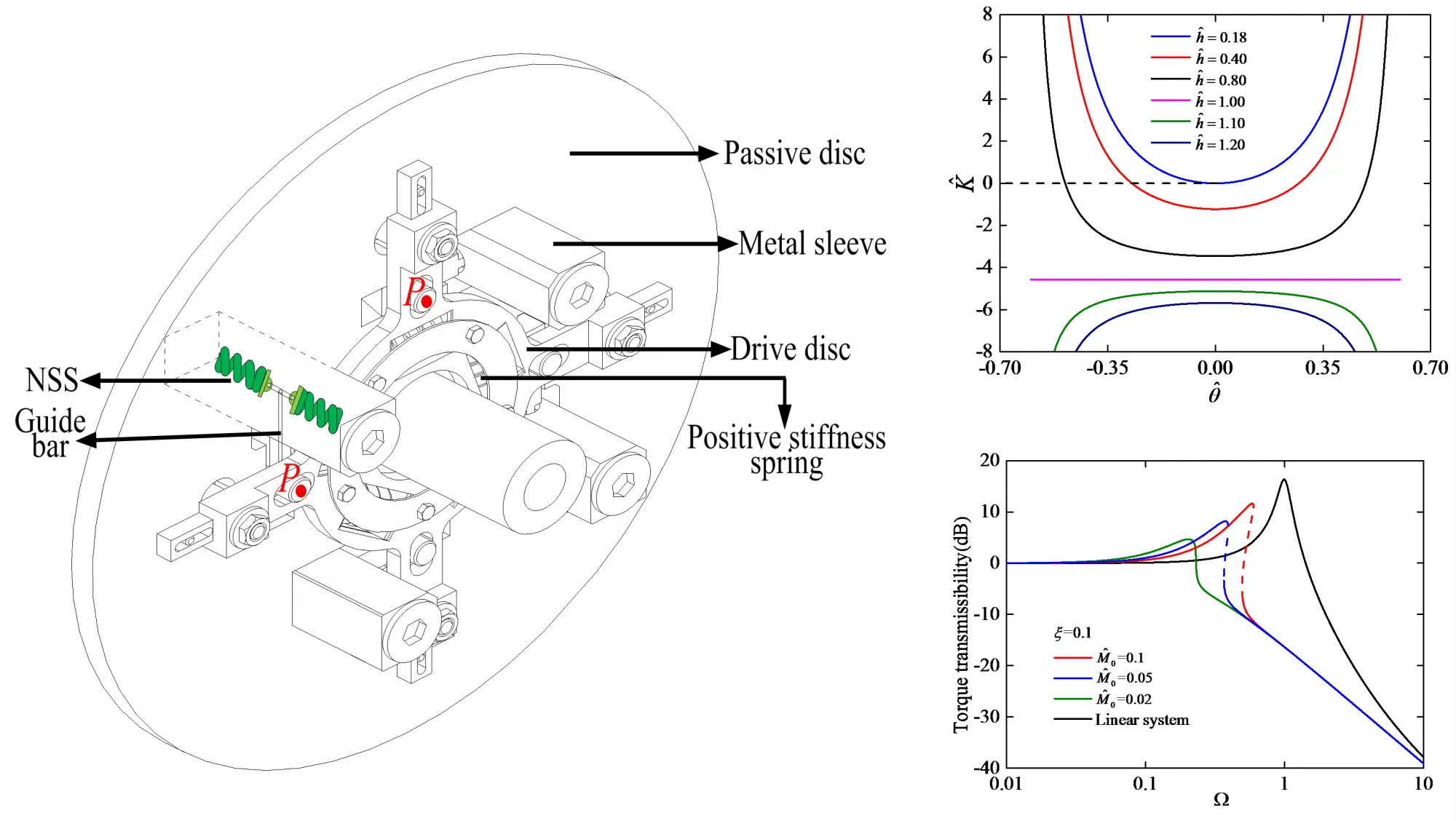
The original principle model of this study is illustrated in Fig. 2. It is an effective method to decrease the dynamic stiffness of the isolation system by paralleling with the NSS. Fig. 3 shows the schematic diagram of the NSS, it is installed in the metal sleeve. The structure consists of two pre-compression springs with stiffness . The one end of the pre-compression springs is fixed to the metal sleeve and the other end is connected to a roller, which is free slide in translational direction. Two connecting bars of length and a guide bar are connected to a roller, which can free roll at the connecting position. The shown in Fig. 3 is the relative angle of torsional isolator drive side and passive side. When 0, two connecting bars of length are on the same line, and here we define that the state of 0 is the static equilibrium position of the system. At this time, the deformation of the pre-compression spring is . Various stiffness characteristics can be obtained by designing different pre-compression deformation . In our design, the negative stiffness structure installed between the drive side and passive side. The position is the force point of negative stiffness structure as shown in Fig. 3, Fig. 4 and Fig. 5.
The oblique view of torsional isolator this paper proposed is shown in Fig. 4. There are two sides, drive side and passive side are linked by positive springs and negative stiffness structures, and the both sides have been designed into a disc structure in the connection place. The positive springs and negative stiffness structures are installed in the disc circumferentially. The orientation of negative stiffness structures installed in torsional isolator is shown in Fig. 4, it is symmetrically arranged on the passive disc. The guide bar is in the plane of the passive disc.
Fig. 2Original principle model of torsional vibration isolation system
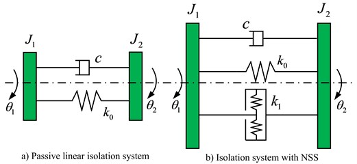
Fig. 3Schematic diagram of negative stiffness structure
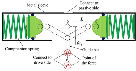
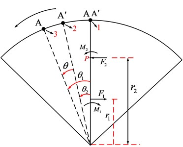
Fig. 5 is structural diagram of the torsional isolator, Fig. 6 shows the quarter force schematic diagram of the torsion isolator. As shown in Fig. 5 and Fig. 6, and are the orthogonal distances from the shaft center to the positive stiffness force and negative stiffness force, respectively. and are the positive stiffness force and negative stiffness force, respectively. and are torsional torques caused by and , respectively. A and A′ are the points on the drive side and passive side, respectively. When the designed constant drive torque has been applied, points A and A’ at the same position 1, the NSS is at the static equilibrium position. And then consider the torsional vibration transfer from drive side to passive side, the point A on drive side turns to the position 3 with angle displacement , and the point A′ on passive side turns to the position 2 with angle displacement , the relative angle displacement between drive side to passive side is . And and are also the angle displacement of the force and , respectively. Note that the number of the positive springs and negative stiffness structures are variable, in this paper, we take and as the number of the positive springs and negative stiffness structures, respectively.
Fig. 4Oblique view of the torsional isolator
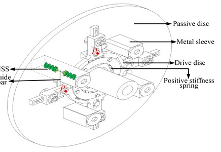
Fig. 5Structural diagram of the torsional isolator
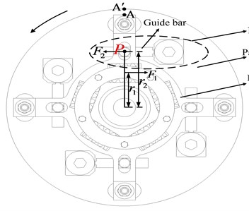
Fig. 6Quarter force schematic diagram of the torsional isolator
This torsional isolation system with NSS can not only transmit a designed constant drive torque but also isolate the torsional vibration with a wider frequency range. It is necessary to explain that, in this paper, the study is based on the fact that the torsional isolator transmits a designed constant drive torque. When the isolator is at rest, the drive side and passive side have an initial certain relative angle displacement, and the NSS is not at the static equilibrium position. As the designed constant drive torque is applied, the NSS of the system reaches the static equilibrium position. After the designed constant drive torque is applied, the torsional isolator will isolate the torsional vibration in this state. And our subsequent analysis is carried out in the case of the designed constant drive torque has been applied.
3. Nonlinear stiffness and static analysis
In this section, the nonlinear stiffness will be analyzed and the influence of the dimensionless pre-compression and spring stiffness ratio on the stiffness characteristics will be discussed. Furthermore, to easily study the dynamic characteristics of this nonlinear system, the relationship between the torque and torsion angle will be approximated by a polynomial using the Taylor series expansion. In addition, the fitting error will be described.
From section 2 and Fig. 6, the total restoring torque can be given by , where is the positive stiffness restoring torque, is the negative stiffness restoring torque. And , where is the stiffness of the positive springs we used in this study, is the deformation of the positive linear spring. According to the structure of negative stiffness from Fig. 3, the negative stiffness force can be given by [23]:
where is the relative torsion angle of the drive side and the passive side, is the bar length, and is the pre-compression deformation of the springs used in the NSS. The negative stiffness restoring torque is:
Thus, the total restoring torque can be obtained by:
When 0, there is no dynamic relative movement between the two sides, the state of 0 is the static equilibrium position of the system as defined in section 2.
It is convenient to define the following dimensionless parameters as:
where is the dimensionless restoring torque, is the dimensionless relative torsion angle displacement of the system, and are the dimensionless configurative parameters, is the ratio of the number of NSS and positive springs, and is the spring stiffness ratio used in the NSS and positive spring stiffness.
In terms of these dimensionless parameters, the dimensionless restoring torque can be derived from Eq. (3) as follows:
Eq. (5) describes the parametric dependence between the dimensionless restoring torque and dimensionless relative torsion angle . By differentiating Eq. (5) with respect to the dimensionless torsion angle , the dimensionless stiffness of the system can be obtained as:
Eq. (6) indicates that the nonlinear stiffness is affected by , and angle displacement through the nonlinear term . From Eq. (6), it can be observed that, the dimensionless parameters , and can affect the nonlinear stiffness through , Considering that and are immutable when the design is complete, here we thus choose as the variable to analyze the influence of . In our design, the parameters and are settled. In this study, we choose 0.8 and 1.6. In order to clearly analyze the nonlinear stiffness, the differentiation of Eq. (6) with respect to the dimensionless torsion angle gives the following dimensionless parameter of the system:
Eq. (7) is the odd function of . When 1, 1 and 1, Eq. (6) represents the constant, convex, and concave functions, respectively. As the parameters and are settled, the nonlinear stiffness becomes constant and is dependent only on the spring stiffness ratio , it is independent of the dimensionless angle displacement in the case of 1.
By substituting 0 into Eq. (6), the dimensionless nonlinear stiffness at the static equilibrium position (SEP) is obtained as follows:
Fig. 7 presents the relation between the dimensionless pre-compression deformation and spring stiffness ratio .
Fig. 7Region of K^SEP for various values of h^ and k^
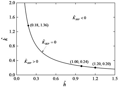
From Fig. 7, the parameter space (, ) has been divided into two regions by the curve 0. In the different regions, the stiffness curves have different relations to the dimensionless angle displacement . The points (0.18, 1.36), (1.00, 0.24), and (1.20, 0.20) lie on the curve 0.
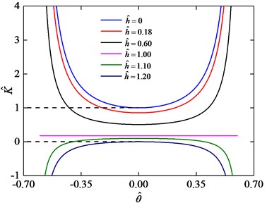
In region 0, the value of the nonlinear stiffness is negative at the static equilibrium position. Fig. 8 depicts the dimensionless nonlinear stiffness curves for 1.36 and various values of . It is observed that when 1, the nonlinear stiffness curve is a straight line. When the 1, the nonlinear stiffness curve is a concave parabola, on which the value of nonlinear stiffness is a minimum at the static equilibrium position. As the system moves away from the static equilibrium position, the dimensionless nonlinear stiffness increases compared with the dimensionless stiffness at the static equilibrium position. When 1, the nonlinear stiffness curve is a convex parabola. It is known that a system with negative stiffness cannot support the load. Similarly, regardless of how we select the values of in region 0, the value of the nonlinear stiffness will always be negative at the static equilibrium position. Thus, in region 0, the parameters and are not suitable for the torsional vibration isolation system.
Fig. 8Stiffness curves for k^= 1.36 and various values of h^
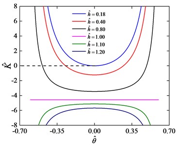
In region 0, the nonlinear stiffness is positive at the static equilibrium position. Fig. 9 depicts the dimensionless nonlinear stiffness curves for 0.20 and various values of . The value of the dimensionless nonlinear stiffness at the static equilibrium position is less than one and larger than zero for 0 1.20 as shown in Fig. 9. When 0 1.20, the nonlinear stiffness curve is a convex parabola on which the stiffness achieves a maximum at the static equilibrium position, the stiffness of the system will be negative when the relative torsion angle increases with a sufficiently large angle displacement . This case cannot be used to design a system to improve the isolation performance [23]. When 0 1, the value of nonlinear stiffness of the system at the static equilibrium position is between zero and one, and the nonlinear stiffness increases following the increase of the relative torsion angle . Especially, when 0, the stiffness of the system at the static equilibrium position is one. The stiffness of this system with NSS will always be larger than the corresponding linear system without NSS. In this case the system with NSS cannot effectively isolate low frequency vibration.
Fig. 9Stiffness curves for value of k^= 0.20 and various values of h^
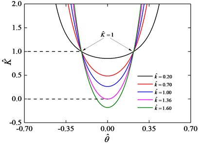
Based on the analysis of stiffness in these two different regions, it can be seen that region 0 with 0 1 is an effective parameters region for good isolation performance. Fig. 10 depicts the dimensionless nonlinear stiffness curves for 0.18 and various values of . In this condition, the curves are concave parabolas, and there is common intersection point at dimensionless nonlinear stiffness 1, this point can be obtained by solving Eq. (6).
Fig. 10Stiffness curves for h^= 0.18 and various values of k^
From the stiffness analysis above, the QZS characteristics can be obtained by carefully choosing the parameters and . The nonlinear stiffness at the equilibrium position becomes zero by enforcing 0 as shown in Eq. (8). Fig. 11 shows the values of and when the stiffness is zero at the static equilibrium position. When 1 and 0.24, the nonlinear stiffness is zero at any location plotted by the black solid line. As increases and decreases, the low stiffness range increases. And in the following analysis, the values 0.80 and 0.31 will be used.
Note that the dimensionless restoring torque in Eq. (5) is a nonlinear function. The Taylor series expansion is employed for the approximation, and can be expanded with the Taylor series up to the third, fifth or seventh order as follows:
where and .
In the following analysis, we choose, 0.80, 0.31. And as mentioned before, 0.8, 1.6.
Fig. 12 shows the accuracy of the third order, fifth order and seventh order Taylor series expansion in fitting the restoring torque.
Fig. 11Stiffness curves with the zero condition at the equilibrium position
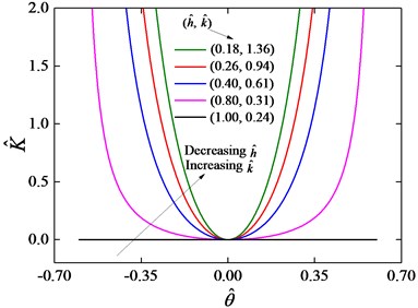
Fig. 12Taylor expansion fitting the restoring torque
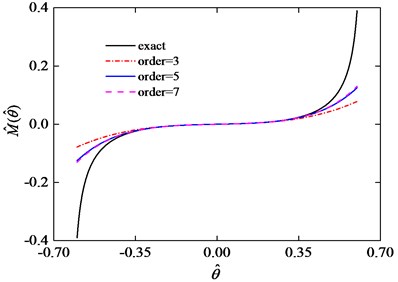
It can be seen from Fig. 12 that the error between the approximate restoring torque and the actual restoring torque increases following the relative torsion angle increases. The fitting error can be given by:
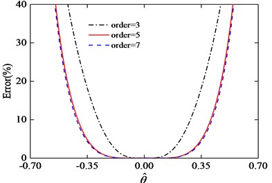
where is the exact solution of Eq. (5), and is approximate solutions of Eq. (9), Eq. (10) and Eq. (11). Fig. 13 shows the error curves of the fitting function in Eq. (9), Eq. (10) and Eq. (11). It can be seen from Fig. 13 that the third order Taylor series has greater error than fifth and seventh order. When in the range of [–0.35, 0.35] the errors of fifth and seventh order Taylor expansion are very similar. Considering the convenience of calculation, we choose the fifth order Taylor expansion to be the approximate expression of Eq. (5).
Fig. 13Error of the third, fifth and seventh order Taylor series expansion
4. Dynamic analysis
In this section, the torque vibration responses will be analyzed, then the isolation performance will be analyzed by the torque vibration transmissibility. In the process of calculation and analysis, the vibration excitation amplitude and damping will be considered as factors influencing the dynamic and isolation performance of the isolator.
4.1. Torsional vibration responses
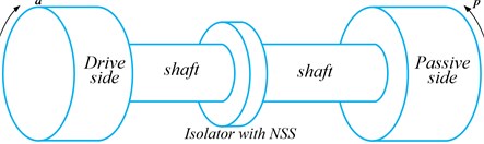
With the model introduced in section 2, the torsional isolator with NSS proposed in this paper is mounted on the shaft between the drive side and the passive side [25], as shown in Fig. 14. This isolator plays a role to prevent the oscillatory torque being transmitted to the right hand shaft [24].
Fig. 14Schematic diagram of two degrees of freedom system under vibratory torque
Considering linear viscous damping between the drive side and passive side, the two degree-of-freedom equations can be given by:
where and are the lumped inertias of the drive side and passive side, respectively. is the linear viscous damping coefficient, is the vibration excitation input from the drive side, and are the amplitude and frequency of the excitation torque, respectively. In this study, the passive side has no vibration excitation, therefore 0.
In order to easily analyze the dynamics of the model, we use the transform to merge Eq. (13) and Eq. (14) as follows: (Eq. (13)Eq. (14)), so the equivalent equation can be described by:
where define The dimensionless parameters can be chosen as:
Then the dimensionless dynamical equation is given by:
Due to the nonlinear characteristics, the fundamental response solution of the dynamic equation will be obtained by using the averaging method [26]. For Eq. (17), the relative angular displacement response of the system in steady-state motions may be assumed to be:
where is response amplitude of the system, while is the corresponding phase angle. According to the theory of averaging method, and are functions of time . Differentiating the Eq. (18a) with respect to the time yields:
Comparing the Eq. (19) and (18b), it can be found that:
From Eq. (20) we can get the expressions of and as follows:
Differentiating the Eq. (18b) with respect to the time , and comparing the Eq. (20) yields:
Substituting the expressions about , and into Eq. (17), and comparing the Eq. (20) the following equation is obtained:
where . Substituting Eqs. (21) into Eq. (23), the expressions of the time change rates of response amplitudes and phase angles are found:
where:
Assuming that the response amplitudes and the phase angles are slowing-varying variables of time, the left hand sides of Eqs. (24) can be approximated by their average values over an excitation cycle:
Then using the approximate expression of restoring torque Eq. (10), the integrations in Eqs. (26) can be given by:
In the steady-state motion, the response amplitudes and phase angles remain unchanged, and thus their derivatives will vanish, that is 0. So, we can get from Eqs. (27) that:
Cancelling out the trigonometric terms with phase angles in Eq. (28), we obtain:
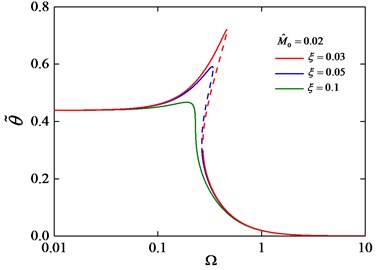
By resolving the Eq. (29), we can obtain the torsional vibration responses of the system. Fig. 15 and Fig. 16 show the torsion amplitude-frequency relationships under different parameters and .
Fig. 15 shows that the amplitude of the system will be increase with the excitation amplitude increase, following the increase of the excitation amplitude the jump phenomenon appears. Fig. 16 shows that amplitude of the system is sensitive to the damping of the system, with the decrease of damping, the nonlinear instability appeared. Therefore, the suitable excitation amplitude and damping are needed to suppress the resonant response [24].
Fig. 15Torsion amplitude-frequency curves under different M^0 with ξ= 0.1
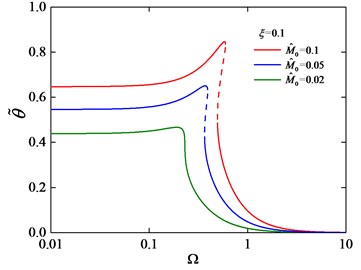
Fig. 16Torsion amplitude-frequency curves under different ξ with M^0= 0.02
4.2. Torque transmissibility
The transmissibility is useful for evaluating the isolation performance and designing a suitable isolator. In this paper, the transmissibility is defined as the magnitude of the torque transmitted to the passive side to that of the excitation torque. According to Eq. (17), the vibration torque transmitted from the drive side to passive side can be described by:
Submitting Eq. (10) and Eq. (18b) into Eq. (30), the transmitted vibration torque is given by:
where . The vibration torque transmissibility can be derived as:
where is the dimensionless excitation amplitude of drive side.
The torsional vibration isolation performance between the designed torsional isolation system and the corresponding linear system has been studied. The linear system is obtained from the proposed system by removing the four negative stiffness structures. The vibration torque transmissibility of this nonlinear isolation system and the corresponding linear system under different parameters and are shown in Fig. 17 and Fig. 18.
Fig. 17Torque transmissibility under different excitation amplitude M^0 with ξ= 0.1
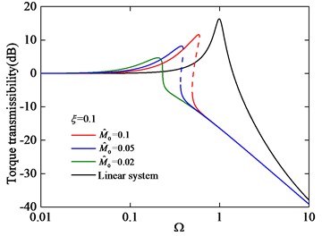
Fig. 18Torque transmissibility under different damping ξ with M^0= 0.02
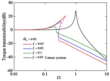
Fig. 17 and Fig. 18 show that the isolator with NSS has a greater isolation frequency range than that of the corresponding linear isolator without NSS. From Fig. 17, it can be seen that the torque transmissibility increases with the excitation amplitude increase and the phenomenon of jump frequency occurs, meanwhile, the isolation frequency range decreases. From Fig. 18, it can be seen that the performance of vibration isolation of this isolator is sensitive to damping, the vibration isolation performance will be better as the damping increase in the resonant region. When 0.02 and 0.1, the torque transmissibility curve is stable. Thus, choosing a suitable damping and vibration environment will be important for the stable application of this isolator.
5. Conclusions
In a powertrain system, torsional vibrations that occur at low frequencies are often difficult to isolate. Currently, in the aspect of translational vibration, researchers are focused on designing new nonlinear isolator with negative stiffness structure to isolate the low frequency vibration. In this paper, we introduced a novel torsional vibration isolator with negative stiffness structure. The negative stiffness force and restoring torque of the system are obtained from the model. Then the nonlinear stiffness characteristics were studied, the results demonstrate that the parameters of spring stiffness ratio and the pre-compression deformation of spring used in negative stiffness structures have great effect on the stiffness of the system. Furthermore, the dynamics of the isolator, including the torsional vibration responses and torsional vibration transmissibility, were studied theoretically. Through the analysis in this paper, this torsional isolator with negative stiffness structures has greater isolation frequency region than that of the corresponding linear isolator. Meanwhile, this isolator will exhibit good stability and isolation performance if the damping and vibration excitation amplitude are chosen carefully.
The torsional vibration isolator studied in this paper provides a way to solve low-frequency vibration problem of some powertrain systems. In future work, the experimental investigations of torsional isolator should be completed. In addition, a new type of torsional isolator with a controllable NSS will be developed. By doing so, the main purpose is to improve the dynamic stability of the isolation system. Secondly, when the transmission torque changes, the torsional isolator will maintain a good vibration isolation performance by controlling the NSS keep in the equilibrium position.
References
-
Liu C. C., Jing X. J., Daley S., Li F. M. Recent advances in micro-vibration isolation. Mechanical Systems and Signal Processing, Vol. 56, Issue 57, 2015, p. 55-80.
-
Xu J. Advances of research on vibration control. Chinese Quarterly of Mechanics, Vol. 36, Issue 4, 2015, p. 547-565.
-
Araki Y., Kimura K., Asai T., Masui T., Toshihiro O., Ryosuke K. Integrated mechanical and material design of quasi-zero-stiffness vibration isolator with superelastic Cu-Al-Mn shape memory alloy bars. Journal of Sound and Vibration, Vol. 358, 2015, p. 74-83.
-
Liu X. T., Huang X. C., Hua H. X. On the characteristics of a quasi-zero stiffness isolator using Euler buckled beam as negative stiffness corrector. Journal of Sound and Vibration, Vol. 332, Issue 14, 2013, p. 3359-3376.
-
Niu F., Meng L. S., Wu W. J., Sun J. G. Design and analysis of a quasi-zero stiffness isolator using a slotted conical disk spring as negative stiffness structure. Journal of Vibroengineering, Vol. 16, Issue 4, 2014, p. 1769-1785.
-
Lu Z. Q., Yang T. J., Brennan M. J., Li X. H., Liu Z. G. On the performance of a two-stage vibration isolation system which has geometrically nonlinear stiffness. Journal of Vibration and Acoustics, Vol. 136, Issue 6, 2013, p. 1-5.
-
Sun X. T., Jing X. J. Multi-direction vibration isolation with quasi-zero stiffness by employing geometrical nonlinearity. Mechanical Systems and Signal Processing, Vol. 62, Issue 63, 2015, p. 149-163.
-
Gatti G., Kovacic I., Brennan M. J. On the response of a harmonically excited two degree-of-freedom system consisting of a linear and a nonlinear quasi-zero stiffness oscillator. Journal of Sound and Vibration, Vol. 329, Issue 10, 2010, p. 1823-1835.
-
Wang Y., Li S. M., Neild S. A., Jiang J. Z. Comparison of the dynamic performance of nonlinear one and two degree-of-freedom vibration isolators with quasi-zero stiffness. Nonlinear Dynamics, Vol. 88, Issue 1, 2016, p. 635-654.
-
Zhu T., William B. C., Robertson S. P., Zander A. Vibration isolation using six degree-of-freedom quasi-zero stiffness magnetic levitation. Journal of Sound and Vibration, Vol. 358, 2015, p. 48-73.
-
Yang J., Xiong Y. P., Xing J. T. Dynamics and power flow behaviour of a nonlinear vibration isolation system with a negative stiffness mechanism. Journal of Sound and Vibration, Vol. 332, Issue 1, 2013, p. 167-183.
-
Huang X. C., Liu X. T., Sun J. Y., Zhang Z. Y., Hua H. X. Effect of the system imperfections on the dynamic response of a high-static-low-dynamic stiffness vibration isolator. Nonlinear Dynamics, Vol. 76, Issue 2, 2014, p. 1157-1167.
-
Huang X. C., Liu X. T., Hua H. X. Effects of stiffness and load imperfection on the isolation performance of a high-static-low-dynamic-stiffness non-linear isolator under base displacement excitation. International Journal of Non-Linear Mechanics, Vol. 65, 2014, p. 32-43.
-
Liu X. T., Huang X. C., Zhang Z. Y., Hua H. X. Influence of excitation amplitude and load on the characteristics of quasi-zero stiffness isolator. Journal of Mechanical Engineering, Vol. 49, Issue 6, 2013, p. 89-94.
-
Abolfathi A., Brennan M. J., Waters T. P., Tang B. On the effects of mistuning a force-excited system containing a quasi-zero-stiffness vibration isolator. Journal of Vibration and Acoustics, Vol. 137, Issue 4, 2015, p. 1-6.
-
Abolfathi A. Nonlinear Vibration Isolators with Asymmetric Stiffness. Ph.D. Thesis, ISVR, University of Southampton, 2012.
-
Sun X. T., Xu J., Jing X. J., Cheng L. Beneficial performance of a quasi-zero-stiffness vibration isolator with time-delayed active control. International Journal of Mechanical Sciences, Vol. 82, Issue 1, 2014, p. 32-40.
-
Wang Y., Li S. M., Cheng C., Jiang X. X. Dynamic analysis of a high-static-low-dynamic-stiffness vibration isolator with time-delayed feedback control. Shock and Vibration, Vol. 2015, 2015, p. 1-19.
-
Zheng Y. S., Zhang X. N., Luo, Y. J., Yan B., Ma C. C. Design and experiment of a high-static-low-dynamic stiffness isolator using a negative stiffness magnetic spring. Journal of Sound and Vibration, Vol. 360, 2016, p. 31-52.
-
Xu D. L., Zhang Y. Y., Zhou J. X., Lou J. J. On the analytical and experimental assessment of the performance of a quasi-zero-stiffness isolator. Journal of Vibration and Control, Vol. 20, Issue 15, 2014, p. 2314-2325.
-
Xu D. L., Zhang Y. Y., Zhou J. X. Zhang J. Characteristic analysis and experimental investigation for a vibration isolator with quasi-zero stiffness. Journal of Vibration and Shock, Vol. 33, Issue 11, 2014, p. 208-213.
-
Li Q., Zhu Y., Xu D. F., Hu J. C., Min W., Pang L. C. A negative stiffness vibration isolator using magnetic spring combined with rubber membrane. Journal of Mechanical Science and Technology, Vol. 27, Issue 3, 2013, p. 813-824.
-
Le T. D., Ahn K. K. Experimental investigation of a vibration isolation system using negative stiffness structure. International Journal of Mechanical Sciences, Vol. 70, 2013, p. 99-112.
-
Zhou J. X., Xu D. L., Bishop S. R. A torsion quasi-zero stiffness vibration isolator. Journal of Sound and Vibration, Vol. 338, 2015, p. 121-133.
-
Liu H., Wang X. J., Wang W. D., Xiang C. L. Design and dynamic characteristics of a torsion isolator with negative stiffness structures. Proceedings of ASME International Mechanical Engineering Congress and Exposition, Phoenix, Arizona, USA, 2016.
-
Wang X. L., Zhou J. X., Xu D. L., Ouyang H. J., Duan Y. Force transmissibility of a two-stage vibration isolation system with quasi-zero stiffness. Nonlinear Dynamics, Vol. 87, 2017, p. 633-646.
Cited by
About this article

This work is partially supported by the National Natural Science Foundation of China (NSFC) under Grant No. 51375047, and this paper is also funded by Graduate Science and Technology Innovation Program of Beijing Institute of Technology under Grant No. 2016CX10018.
