Abstract
Three configurations that incorporate a negative stiffness element and an inerter in parallel connection into the conventional isolator are considered to investigate their vibration characteristics from the point of view of resonance frequencies and displacement transmissibility. Analytical and numerical results are evaluated and compared with each other. It is illustrated that for the configuration of the inerter and an additional viscous damper in series connection which are then connected with the negative stiffness element in parallel, the isolator shows a better vibration isolation performance.
1. Introduction
Passive vibration isolation techniques have always been popular and favoured by researchers because of their reliability, simplicity and low cost. Recently great attention has been given to two novel kinds of passive devices: negative stiffness elements and inerters [1, 2]. Both have become effective vibration suppression tools which have been demonstrated in many vibration control applications, including engineering structures, vehicle suspensions, railway vehicles, stay cables and etc. They all share a common property: a force-displacement relationship with an apparent negative slope.
The use of a negative stiffness element parallel to a positive stiffness element can achieve a relatively low-dynamic stiffness but a high-static stiffness for an isolator, without causing large static deflection under static load. This layout implements a so-called quasi-zero stiffness (QZS) isolator and offers good low-frequency vibration isolation performance. There are already various forms of negative stiffness mechanisms used to obtain negative stiffness and combination with positive stiffness elements to construct QZS isolators [3-6].
A mechanical inerter is described as a two-terminal device with the property that it produces a force proportional to the relative acceleration between the end nodes. The constant of proportionality is called inertance with a unit of kilogram [7]. This device, a dual port element, completes the analogy between a spring-damper-inerter mechanical network and an inductor-resistor-capacitor electrical network. Also, an inerter, in a sense, is an inertial element. Nowadays the physical realizations of an inerter can classified into two categories, that is flywheel-based inerters [8, 9] and non-flywheel inerters [10, 11].
Although extensive investigations have been conducted on the vibration isolation characteristics of QZS-based or inerter-based isolators, separately, there is no literature addressing vibration isolation performance of an isolator incorporating a QZS and an inerter simultaneously, to the best of the authors’ knowledge. This paper investigates three linear isolators with parallel connection of quasi-zero stiffness and inerter dampers under base harmonic excitation. Their natural frequencies and displacement transmissibility, as a function of the isolator parameters, are evaluated and compared with each other.
2. Mathematical modelling of three isolators
In this section, the ordinary differential equations as well as the expressions of displacement transmissibility for each studied isolator under base excitation will be presented. Subsequently, some numerical results will be shown and compared with each other in next section.
2.1. Model 1
This isolator with the model 1 incorporates an inerter and a negative stiffness element in parallel connection directly into a conventional isolator, as shown in Fig. 1. The governing equation is expressed as:
where and are the absolute displacements of the sprung mass and base excitation, respectively; , and are the mass, damping and positive stiffness coefficients of the isolator, respectively; and are the inertance and absolute value of the negative stiffness coefficient of the isolator, respectively. For brevity, this isolator is denoted as (). Introducing non-dimensional parameters:
where is the amplitude of the base motion . Eq. (1) can be written as:
where the primes denote derivatives with respect to non-dimensional time .
The displacement transmissibility of this isolator is given by:
Additionally, Eq. (2) can be rewritten as:
where (or ) and are the undamped natural frequency and damping ratio of the isolator, respectively; They have the following expressions as:
For the isolator with the quasi-zero stiffness discussed in this paper, one has , and so as to maintain the stability of the isolator in reality. Obviously, from Eq. (5) the isolator () has a much lower natural frequency than that of the corresponding isolator with the addition of the negative stiffness only, denoted as () or the addition of the inerter only, denoted as (), which has the natural frequency or .
Fig. 1An isolator (m,c,kp,kn,b) with direct parallel connection of QZS and an inerter
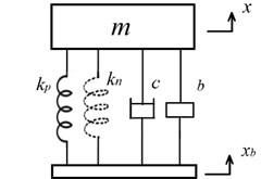
Fig. 2An isolator (m,c,kp,kn,b,c1) with a damper in series connection with the inerter
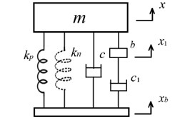
2.2. Model 2
This isolator with the model 2 uses a damper in series connection with the inerter, as shown in Fig. 2, and is denoted as (). It has an additional degree of freedom , which has an equation of motion as follows:
Eliminating from Eqs. (7) and (8) yields:
where the non-dimensional parameter , and other non-dimensional parameters are the same as those of Eq. (2). Instead of seeking the analytical solutions of undamped natural frequencies for this isolator, the characteristic roots or poles of this isolator will be numerically calculated as a function of the non-dimensional parameter by utilizing the root-locus method.
Additionally, the displacement transmissibility of this isolator is given by:
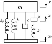
2.3. Model 3
This isolator with the model 3 uses a positive stiffness element in series connection with the inerter, as shown in Fig. 3, and is denoted as (), which has an equation of motion as follows:
where the non-dimensional parameter . The displacement transmissibility of this isolator is given by:
Fig. 3An isolator (m,c,kp,kn,b,k1) with a spring in series connection with the inerter
3. Results and discussion
Fig. 4 shows the effect of and on for (), and Fig. 5(a) and (b) give and views of Fig. 4, respectively, which illustrate that the undamped natural frequency is a decreasing function with respect to and ; moreover, is more sensitive dependence on compared to . Fig. 6 and Fig. 7 show the root-locus plot of () and () with respect to different for 1.0 and 0.1 as , , respectively. From results shown as in these figures, it is found that (1) () may achieve a lower undamped natural frequency with relative ease compared with () and (); (2) vibration characterises of () are more sensitive dependence on compared with those of (); relatively speaking, the former normally has a low undamped natural frequency and a high damping ratio and the reverse is true for the latter.
Fig. 4The effect of α and β on Ωn of m, c, kp, kn, b
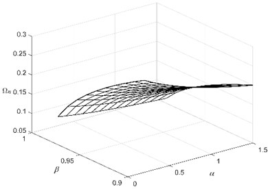
Fig. 5a) Ωn-α view and b) Ωn-β view of Fig. 4
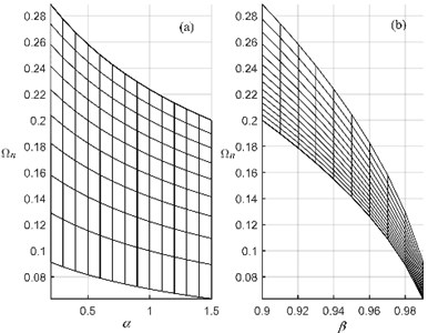
Fig. 6The root-locus plot of (m,c,kp,kn,b,c1)
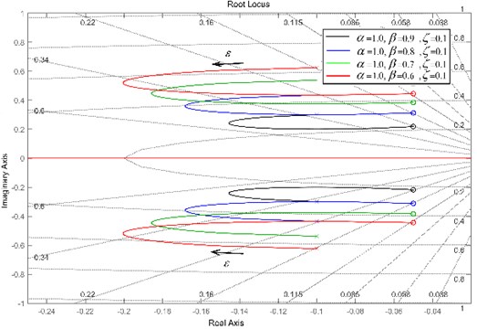
Fig. 7The root-locus plot of (m,c,kp,kn,b,k1)
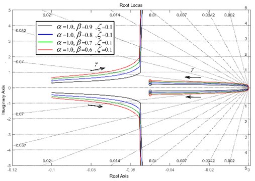
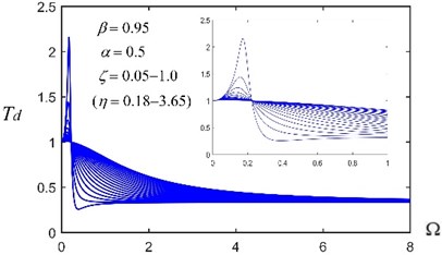
Fig. 8Transmissibility Td of (m,c,kp,kn,b) with different α and ζ and given β= 0.95
a)
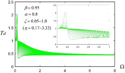
b)
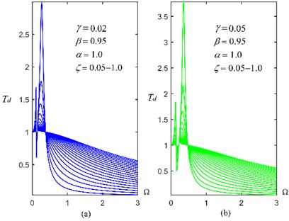
Fig. 8, Fig. 9 and Fig. 10 give the displacement transmissibility of three isolators with different, , and for a given 0.95, respectively. It is found that (1) when becomes larger, the of () will not tend to zero, which is totally different from () and (); (2) () has two resonant frequencies (or characteristic roots), and the frequency band for effective vibration isolation is influenced by the position of the larger frequency; (3) () has better comprehensive vibration isolation performances in terms of the suppression of low and high frequency-excited vibration and an appropriate resonance peak value, compared with () and ().
Fig. 9Transmissibility Td of (m,c,kp,kn,c1) with different ε and ζ and given β= 0.95
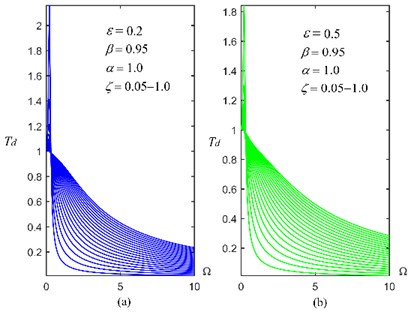
Fig. 10Transmissibility Td of (m,c,kp,kn,k1) with different γ and ζ and given β= 0.95
4. Conclusions
An isolator incorporating a negative stiffness element and an inerter in parallel connection into a conventional isolator can achieve a much lower natural frequency, compared with the corresponding isolator with the addition of a negative stiffness or an inerter only. The isolator () exhibits some better vibration isolation performances. Future researches will be conducted to other vibration characteristics, such as the shock isolation performance.
References
-
Li H., et al. Negative stiffness devices for vibration isolation applications: a review. Advances in Structural Engineering, Vol. 23, Issue 8, 2020, p. 1739-1755.
-
Chen M. Z. Q., Hu Y. L. Inerter and Its Application in Vibration Control Systems. Springer Nature Singapore Pte Ltd. and Science Press, Beijing, 2019.
-
Carrella A., et al. Force and displacement transmissibility of a nonlinear isolator with high-static-low-dynamic-stiffness. International Journal of Mechanical Sciences, Vol. 55, Issue 1, 2012, p. 22-29.
-
Liu X. T., et al. On the characteristics of a quasi-zero stiffness isolator using Euler buckled beam as negative stiffness corrector. Journal of Sound and Vibration, Vol. 332, Issue 14, 2013, p. 3359-3376.
-
Zhou J. X., et al. Nonlinear dynamic characteristics of a quasi-zero stiffness vibration isolator with cam-roller-spring mechanisms. Journal of Sound and Vibration, Vol. 346, Issue 23, 2015, p. 53-69.
-
Carrella A., et al. On the design of a high-static-low-dynamic stiffness isolator using linear mechanical springs and magnets. Journal of Sound and Vibration, Vol. 315, Issue 3, 2008, p. 712-720.
-
Smith M. C. Synthesis of mechanical networks: the inerter. IEEE Transactions on Automatic Control, Vol. 2, Issue 10, 2002, p. 1657-1662.
-
Wang F.-C., Su W.-J. Impact of inerter nonlinearities on vehicle suspension control. Vehicle System Dynamics, Vol. 46, Issue 7, 2008, p. 575-595.
-
Wang F.-C., et al. Designing and testing a hydraulic inerter. Proceedings of the Institution of Mechanical Engineers, Part C: Journal of Mechanical Engineering Science, Vol. 225, Issue 1, 2011, p. 66-72.
-
Gartner B. J., Smith M. C. Damper and Inertial Hydraulic Device. U.S. Patent 13/577,234, 2011.
-
Swift S. J., et al. Design and modelling of a fluid inerter. International Journal of Control, Vol. 86, Issue 11, 2013, p. 2035-2051.
Cited by
About this article

