Abstract
Considering that the static load of marine equipment and the packing space of vibration isolation is limited, a novel quasi-zero-stiffness-isolator (QZSI) using magnets as negative stiffness is designed. The conditions that the QZSI realizes quasi-zero-stiffness at the equilibrium position is obtained by analyzing the static characteristics. The dynamical model of system under a vertical harmonic force is established. The harmonic balance method is used to analyze the dynamic characteristics of QZSI, and the amplitude- frequency relationship expression and force transmissibility are deduced. The influence of different parameters on the performances is analyzed by means of controlling variables. It is shown that the novel QZSI can reduce the response peaks and extend the frequency band of isolator, and that the QZSI provided suitable system parameters can outperform the linear system.
1. Introduction
Vibration of mechanical equipment is the main source of the ship’s radiated noise. The low frequency vibration is the key factor that affects the acoustic stealth performance of the ships. How to suppress low frequency vibration effectively has always been a hot issue in the field of vibration control. In general, the lower limit of effective vibration isolation frequency is times of the natural frequency [1]. According to the theory of vibration isolation, to broaden the vibration isolation band, the stiffness should be reduced, but this will reduce the loading capacity of system. In order to overcome this contraction, many scholars have proposed an isolator so-called quasi-zero-stiffness isolator (QZSI) [2]. The QZSI provided suitable system parameters can achieve zero stiffness, ultra-low stiffness, or negative stiffness characteristics [3]. Carrella and Kovacic et al [4-6] designed a QZSI consisting of two oblique springs providing a negative stiffness and a vertical spring providing a positive stiffness, and the amplitude-frequency characteristics and transmission characteristics were studied in detail. Meng et al. [7] proposed a design of QZSI consisting of variable thickness and equal thickness butterfly spring, and the influence of parameters on the transmission was investigated by the average method.
In this paper, considering the narrow installation space on ship, a new compact quasi-zero-stiffness isolator using magnets as negative stiffness is designed. The paper is organized as follows. In the section Ⅱ, the model of QZSI is introduced. The non-dimensional force and stiffness characteristics of the QZSI are analyzed. In the section Ⅲ, the dynamical model of system under a vertical harmonic force is established and the influence of system parameters on the dynamic characteristics is discussed. Finally, the conclusion is presented.
2. Static analysis
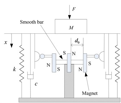
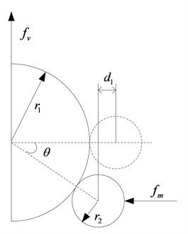
The structure of the novel quasi-zero-stiffness isolator is depicted in Fig. 1(a). The central permanent magnet is wound around the coil, and its position is fixed. The left and right permanent magnets are free to move in the horizontal direction on the smooth bar. The negative stiffness mechanism consists of magnets, semicircle cam and roller. The radius of the cam is , and the radius of the roller is . The vertical linear spring’s stiffness is . The damp of the vibration isolation system is linear viscous damp, and its coefficient is . When the system reaches the static equilibrium position, the distance between two rejecting magnets is . The isolator modeling when the system is excited is shown in Fig. 1(b). The coordinate defines the displacement from the equilibrium position.
Fig. 1a) Schematic of the QZS isolator, b) schematic diagram of static analysis of roller and cam
a)
b)
The magnetic force between two rejecting magnets is given by [8]:
where is the magnetic constant and is the distance between two rejecting magnets. Considering Eq. (1) and the static analysis of roller and cam shown in Fig. 1(b), the magnetic force when the isolator is running is given by:
where . Thus, the relationship between the applied force and displacement is given by:
Introducing the non-dimensional parameters:
Eq. (3) becomes:
The non-dimensional stiffness of the system can be obtained by Differentiating Eq. (4):
By setting 0 and 0 in Eq. (5), we get:
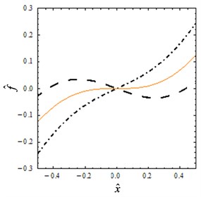
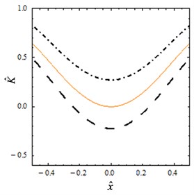
Fig. 2Static characteristics: a) non-dimensional force-displacement, b) stiffness-displacement for different values: Dot-dashed line α= 0.7, solid line α=αQZS= 0.81 and dashed line α= 0.9
a)
b)
When the parameter 0.9, the curves of the non-dimensional force and stiffness for several values of are shown in Figs. 2(a) and (b). As shown in the Fig. 2(a), the nonlinearity of the system becomes stronger with the increase of the parameter . In particular, it can be seen from Fig. 2(b) that the non-dimensional stiffness reaches its minimum at the static equilibrium position. When the parameter , the vertical spring plays a leading role and the stiffness is always greater than zero. When the parameter , the isolator will achieve zero stiffness at the static equilibrium position. When the parameter , the system exhibits negative stiffness in some areas.
By applying Taylor-series expansion to third order for small , Eq. (4) results in:
Differentiating Eq. (7), the stiffness is obtained:
3. Dynamic system behavior
3.1. Dynamic modeling
The dynamical model of the system under a vertical harmonic force is shown in Fig. 1, and the non-dimensional equation of motion is:
where , , , , , .
Assuming that the basic solution of the system:
For convenience, let 1. Inserting Eq. (10) into Eq. (9), and neglecting the higher order term, the coefficients of cosine and sine should be zero:
Solve Eq. (11), 0 is obtained. Introduce , where is the response amplitude of the system. Using 1, the amplitude-frequency expression is given by:
The non-dimensional transmitted force, which is shown in Fig. 1, is given by:
Using the Harmonic Balance theory, the force transmissibility is given by:
The force transmissibility of the linear system is given by [5]:
3.2. Amplitude-frequency characteristic
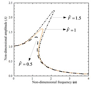
Two cases are analyzed in detail as follows: (1) When parameters 0.2, 1.2, the excitation amplitude is varied. Fig. 3(a) shows the amplitude as function of the frequency for several values of . It can be seen that the system exhibits obvious nonlinearity and the resonance peak increase as the excitation force amplitude increases.
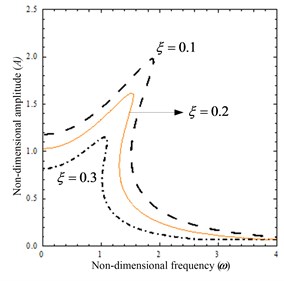
(2) When parameters 1, 1.2, the damping ratio is varied. Fig. 3(b) shows the amplitude as function of the frequency for several values of . As the damping ratio increases, the response peak and resonant frequency decrease, and the vibration is effectively suppressed.
Fig. 3The amplitude-frequency curves: a) when parameter F^ is varied, b) when parameter ξ is varied
a)
b)
3.3. The force transmissibility analysis
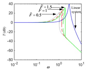
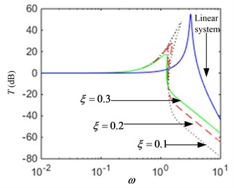
The influence of the external excitation force and system parameters on the transmissibility will be analyzed in detail as follows: (1) When parameters 0.2, 1.2, the force transmissibility for several values is plotted in Fig. 4(a). If the excitation amplitude is increased, then the resonance peak and the starting frequency of vibration isolation is greater, and the effective frequency range of vibration isolation is smaller. So, the vibration performance will be worse. (2) When parameters 1, 1.2, the force transmissibility for several values is plotted in Fig. 4(b). If the damping ratio is increased, then the resonance peak is smaller, and the vibration isolation performance of the system in the low frequency region is enhanced, but the performance is weakened in the high frequency region.
Fig. 4The transmissibility curves: a) when parameter F^ is varied, b) when parameter ξ is varied
a)
b)
The force transmissibility of a linear vibration system given by Eq. (17) is also plotted in Fig. 4. It can be seen that all the quasi-zero-stiffness system for several parameters values outperform the linear system. According to the analysis above, it is possible to obtain a good low frequency vibration isolation performance by designing the appropriate system parameters.
4. Conclusions
In this paper, a new structure of quasi-zero-stiffness isolator is proposed. The isolator consists of the rejecting magnets providing a negative stiffness and two vertical mechanical springs providing a positive stiffness. In the static analysis, the condition that the system realizes quasi-zero-stiffness at the equilibrium position is analyzed. The dynamic characteristics of system are analyzed by the harmonic balance method. The influence of system parameters on amplitude-frequency characteristics is obtained. Through the force transmissibility, the study shows that the novel quasi-zero-stiffness isolator outperform the linear system, and it has the advantages of widening the vibration isolation range and improving the low-frequency vibration isolation performance by designing the appropriate structural parameters.
References
-
Rivin E. I. Passive Vibration Isolation. ASME Press, New York, 2001.
-
Zhang J. Z., Li D., Chen M. J., et al. An ultra-low frequency parallel connection nonlinear isolator for precision instruments. Key Engineering Materials, Vol. 257, 2004, p. 231-238.
-
Ahn H. J. Performance limit of a passive vertical isolator using a negative stiffness mechanism. Journal of Mechanical Science and Technology, Vol. 12, 2008, p. 2357-2364.
-
Carrella A., Brennan M. J., Waters T. P. Static analysis of a passive vibration isolator with quasi-zero-stiffness characteristic. Journal of Sound and Vibration, Vol. 301, 2007, p. 678-689.
-
Carrella A., Brennan M. J., Kovacic I., et al. On the force transmissibility of a vibration isolator with quasi-zero-stiffness. Journal of Sound and Vibration, Vol. 4, 2009, p. 707-717.
-
Kovacic I., Michael J. B., Timothy P. W. A study of a nonlinear vibration isolator with a quasi-zero stiffness characteristic. Journal of Sound and Vibration, Vol. 3, 2008, p. 700-711.
-
Meng L. H., Sun J. G., Wu W. J. Theoretical design and characteristics analysis of a quasi-zero stiffness isolator using a disk spring as negative stiffness element. Shock and Vibration, Vol. 4, 2015, p. 1-19.
-
Mccaig M. Permanent Magnets in Theory and Practice. Pentech Press, Plymouth, 1977.
About this article

This research is supported by the National Natural Science Foundation of China (51579242, 51509253, 51509255), and by the Naval University of Engineering Foundation (425517K143).
