Abstract
The article is devoted to the improvement of the vibration isolation and shockproof properties of the shock absorber used in the vibration isolation compensator system of the pumping unit (PU). The set task is to create an elastic damping system with the desired low (quasi-zero) stiffness, which makes it possible to reduce the detrimental effect of pumping unit vibrations both on human health and on the equipment itself. High internal dynamic (vibration) loads are the main causes of early failure of pumping units, which are transmitted to the equipment through pipelines and foundations, mainly due to various operational factors. A promising trend in increasing the operating reliability and efficiency of pumping and power equipment is the use of a vibration-isolating compensator system (VICS). To obtain greater efficiency of vibration isolation, it is proposed to apply a modern method of vibration damping – the use of elastic mechanical systems with quasi-zero stiffness. The damping devices with a quasi-zero stiffness effect were studied. An assessment of the operability and effectiveness of these dampers at oil and gas facilities was given. Based on the information studied, a new concept of a quasi-zero stiffness damping device is proposed. The method of mathematical analysis determined its power curve. A 3D model of the damper device was built using a simulation software. The functional check of the damper was performed with mathematical modeling carried out on the computing device with the help of a specialized Ansys software that allows performing a system analysis of an object using the finite element method. The following results were obtained: the design of the damper with the effect of quasi-zero stiffness allows to widen the range of basement load transmission coefficient reduction towards low frequencies. The low rigidity of the system at the operating point ensures low values of the frequency of natural oscillations, and, consequently, high vibration isolation qualities.
1. Introduction
The economic viability of the operation of main pipelines largely depends on the equipment integrity of an oil pumping station (OPS).
As of today, the energy enterprises and the CIS countries have more than tens of thousands of pumping units in operation. Most of them have been in operation for decades. Working at high capacities, the units exhaust their service life. Wear relates to not only the line section, but also the entire OPS as a whole. Therefore, increasing the reliability and efficiency of equipment and the OPS itself seems to be one of the major challenges, the solution of which can be high production quality requirements, equipment maintainability of and appropriate operation technology.
Among the options to increase the safety and efficiency of the units, it is worth noting the following:
1) setting the optimal revolution rate of the unit’s shaft;
2) improvement of the bearing assemblies service conditions;
3) usage of detectors for rotor misalignment and imbalance;
4) usage of modern diagnostics equipment;
5) installation of vibration-isolating compensating systems (VICS).
The use of these solutions allows increasing the safety of main pipelines, thereby reducing the risk of failure.
The introduction of a VICS not only increases reliability, but also reduces operating costs by reducing the equipment wear rate. The primary feature of the VICS is the introduction of a set of vibration-isolating compensator elements and systems that make it possible to reduce or prevent external destabilizing factors and internal dynamic overloads on the pumping unit. Vibration damping occurs due to the absence of a rigid connection between the base (foundation) of the pumping unit (PU), the pipeline and the unit itself. The application of the system made it possible to mount a 1 to 8 MW power pump on an elastic foundation [1].
The main element of the VICS is an elastic-damper support – a shock absorber installed between the foundation and the unit frame. The use of this support reduces the transfer of pump dynamic (vibration) loads to the foundation by 50 or more times.
To protect process equipment from harmful vibration, it is advisable to use passive systems as the most unsophisticated and cost-effective. One of the main characteristics of a vibration damper is the frequency of its free oscillations. The smaller it is, the wider the frequency range of the driving force at which the vibration damper performance is effective [2].
Obtaining vibration-protective systems with a low natural vibration frequency is achieved through the application of quasi-zero stiffness. A quasi-zero stiffness system is an elastic system with a nonlinear force characteristic, which at some instant in time has almost zero stiffness.
A distinctive feature of systems with quasi-zero stiffness is that in the operating range these systems have a flat power characteristic section and, therefore, have low stiffness, but at the same time have a high bearing capacity in the equilibrium [3].
It should be noted that today such systems are actively developing in vibration and shock damping, since they provide an almost complete absence of transmitted dynamic force, which makes them extremely effective in vibration isolation means. Concepts for the implementation and application of systems with quasi-zero stiffness can be found in the works of A. N. Zotov, A. R. Valeev, Yu. A. Buryanov, M. V. Silikov and others.
2. Development and research of a damper with quasi-zero stiffness effect
The authors of this article propose their own concept of a damping device with the effect of quasi-zero stiffness, which is described below.
A damping device based on the already known AGP-2 damper is proposed. The AGP-2 damper is used as part of a vibration isolating compensating system (VCS) and is designed to reduce vibration loads on the foundation generated by the rotating parts of the pump.
Hydrofilm dampers AGP-2 (Fig. 1) is the most effective in its grade and is actively used today. The damper is mounted between the frame and the foundation of the pumping unit along the perimeter of the structure. The number of installed dampers depends on the beared load [4].
Fig. 1Hydrofilm damper AGP-2 in section
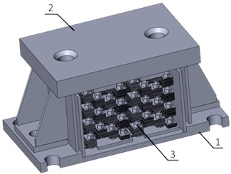
The damper consists of a body (1), a cover (2), and a shock-absorbing package assembled with special corrugated plates (3). To dampen vibrations, the space between the plates is filled with grease lubricant.
To obtain a non-linear power curve, it is necessary to make changes to the damper design. Based on the analysis of known quasi-zero stiffness systems, it was decided to add additional elastic elements, called “stiffness correctors”. The correctors themselves are compression springs with a linear force curve, with swivel joints at both ends.
Fig. 2Hydrofilm damper with quasi-zero stiffness effect
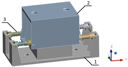
The correctors (3) are fixed between the body (1) and the cover (2) of the damper. The swivel joint allows the correctors to rotate freely in the place of their attachment along the axis.
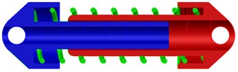
Loss of the stiffness corrector spring stability in the axial direction is eliminated due to the use of guide elements in the corrector design (Fig. 3).
Fig. 3Hardness corrector
When exposed to a load uniformly distributed over the upper plane of the cover (2) of the damper, the package of hydrofilm plates springs along with the stiffness correctors are deformed. In a certain travel range, these correctors (3) compensate for the elastic force of the internal hydrofilm shock absorber, thereby creating the effect of quasi-zero stiffness of the support [5].
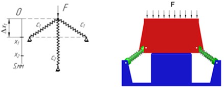
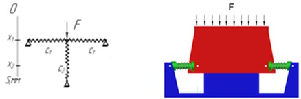
Let us consider the mechanics of a hydrofilm damper with the effect of quasi-zero stiffness (Fig. 4, 5).
Force begins to act on the damper, which meets the resistance of the stiffness corrector springs and the hydrofilm damper itself.
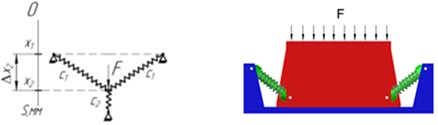
As the acting force increases, the shock absorber deforms and its height decreases. Upon reaching the horizontal position of the stiffness corrector springs (Fig. 4(b)), the upward resisting forces of these springs compensate each other. In the vertical plane, as the force further increases, these springs change their force direction and begin to act co-directionally to the force . This effect is called the “leap-over point”.
As a consequence of the “leap-over”, the corrective springs begin to expand (Fig. 4(c)), acting in the direction of the applied force (quasi-zero stiffness appears).
The effect of almost zero stiffness can be clearly seen by plotting the power curve of this hydrofilm damper. Taking into account the damper design load along the axis of 2000 kg, it is necessary to construct a graph with the quasi-zero stiffness lies within this range.
Boundary conditions.
Of the first kind: .
Second kind: .
Third kind: .
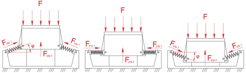
Fig. 4The effect of forces on a hydrofilm damper with the effect of quasi-zero stiffness
a)
b)
c)
Fig. 5Forcing scheme
Let us carry out a preliminary mathematical analysis [6]. The system consists of 4 () correctors and one load-bearing elastic element (corrugated plate package) with stiffness of . The operating position, the stiffness of the correctors in the operating position Eq. (1):
The total stiffness of the system Eq. (2):
Thus, we obtain the condition of quasi-zero stiffness for this system Eq. (3):
Let the bearing spring in the compressed state be deformed by the value . Then, taking into account the condition of quasi-zero stiffness, the power characteristic of the system looks as follows (Eq. (4)):
From the equation obtained, one of the beneficial properties of a quasi-zero stiffness system with a bearing element can be seen - the static load does not depend on the corrector parameters. Therefore, leaving the stiffness correctors unchanged, it is possible to change the deformation of the loadbearing damper, and the system will already be tuned to a different load.
When the condition of quasi-zero stiffness is met, the force characteristic is transformed Eq. (5) and (6):
In dimensionless form Eq. (7):
Dimensionless parameters are presented below Eq. (8):
As an parameter analysis result, it was found that quasi-zero stiffness is achieved with the following parameters:
1) Base stiffness, 990 N/mm;
2) Compression at design load, 46 mm;
3) Rigidity of a one corrector spring, 350 N/mm;
4) Outer diameter corrector spring, 26 mm;
5) Wire diameter corrector spring, 6 mm;
6) Number of the corrector spring turns, 7.
The optimal load (i.e. when quasi-zero stiffness is achieved, and, accordingly, the damping and impact properties are the best) is 20 kN.
To check the obtained parameters and build the power curve of the shock absorber, it was computationally modeled. Structural elements, their quantity and the material which they are made from:
1) Вody (1 pcs) – steel 65G;
2) Сover (1 pcs) – steel 65G;
3) Spring of the stiffness corrector (4 pcs) – 60S2A;
4) Body of the stiffness corrector: small (4 pcs), large (4 pcs) – steel 65G.
This model was calculated in the Ansys finite element analysis software.
The lower part of the body (1) is rigidly fixed in space, the upper part of the cover (2) is uniformly applied force . The swivel joint allows the correctors to rotate freely in the place of their attachment along the axis.
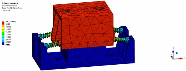
The general view of the model is shown in Fig. 6.
Fig. 6Ansys software model of a hydrofilm damper with the quasi-zero stiffness effect (deformed FEM structure)
The gradual load was applied to the computer model. The obtained values of the applied load and damper deformation are plotted on the graph.
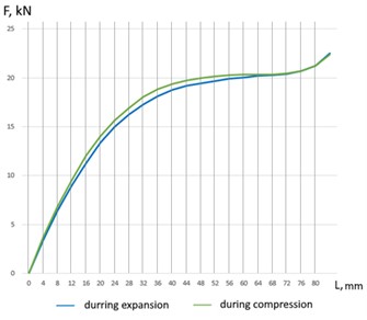
The power curve of the damping package of corrugated plates located inside the housing is shown in Fig. 7.
Fig. 7Power curve of a damping package of corrugated plates in grease lubrication
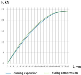
For the damper design load along the axis of 2000 kg, springs of the stiffness corrector were selected. The stiffness of each spring was 350 N/mm. The force characteristic of the stiffness corrector springs is shown in Fig. 8.
Fig. 8Power characteristic of the stiffness corrector springs
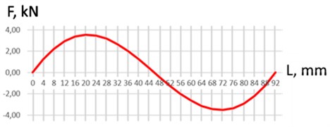
The power curve of a hydrofilm shock absorber with quasi-zero stiffness is the sum of the two graphs presented above and is shown in Fig. 9.
Fig. 9Power characteristic of a hydrofilm shock absorber with the effect of quasi-zero stiffness
According to the results of the solution analysis, the optimal corrector springs stiffness was found to be 350 N/mm, which makes it possible to obtain a damper quasi-zero stiffness at a design load of 20 kN.
3. Conclusions
An analysis of a hydrofilm damper with the quasi-zero stiffness effect showed the best vibration damping and impact characteristics that can be used at oil and gas facilities in order to increase the reliability and durability of the equipment used.
Based on the results of mathematical analysis and computer modeling the following were determined:
1) the stiffness of the damper base (990 N/mm);
2) the correctors stiffness (350 N/mm);
3) the shock absorber overall dimensions (392 mm×170 mm×248 mm);
4) the operating shock absorber height (198 mm);
5) initial position of stiffness correctors (inclination angle 30°, spring length 93 mm), as well as their attachment points to the load-bearing elements.
The use of hardened corrugated plates in the shock absorber design makes it possible to operate it at temperature range of minus 100 °C up to plus 600 °C with the vapor presence of oil, diesel fuel, and mineralized water in the air.
Dampers do not require constant or special maintenance. The type of maintenance required is periodic, within the main equipment maintenance schedule. The annual visual inspection the shock absorbers for mechanical damage and leakage of the damping fluid, check the tightness of the fasteners is recommended.
References
-
A. G. Gumerov et al., Vibration-Isolating Compensating System of Pump-Energy Units. Ufa, Russia: GUP IPTER, 2008.
-
A. A. Gruzdev, G. G. Tarabrin, E. D. Plekhov, and Others, “Experience in vibrodiagnostics and reduction of vibration levels,” Journal of Pipeline Transport, Vol. 21, No. 10, pp. 18–19, 1997.
-
P. M. Alubazhev and A. A. Gritchin, Vibration Protection Systems with Quasi-Zero Stiffness. Saint Petersburg, Russia: Mashinostroenie, 1986.
-
E. T. Grigoriev, Calculation and Design of Shock Absorbers. Moscow, Russia: Mashgiz, 1969.
-
P. E. Tovsik, A. S. Shekhovtsev, and V. A. Shekhovtsev, “Mesis Farm,” Journal of Bulletin of St. Petersburg State University, Vol. 1, No. 3, pp. 62–67, 2008.
-
A. N. Zotov and A. R. Valeev, Protection Against Vibration and Shock by Systems with Quasi-Zero Stiffnes. Ufa, Russia: Oil and Gas Business, 2013.
About this article

The authors have not disclosed any funding.
The datasets generated during and/or analyzed during the current study are available from the corresponding author on reasonable request.
Gareev Ainur under the guidance of Anvar Vallev: conducted a study of systems with quasi-zero rigidity; developed a new design of a shock absorber with quasi-zero rigidity for a pumping unit; conducted a mathematical analysis of this design; investigated the behavior of the structure using computer modeling.
The authors declare that they have no conflict of interest.
