Abstract
Based on harmonic balance calculation technology with a single-passage phase-lag periodic boundary, the influence of tip gap size on the aerodynamic damping characteristics of rotor for first-order torsional vibration is analyzed with energy method. This research shows that the aerodynamic damping coefficient of the blade has a parabolic distribution law of first decreasing and then increasing with the increase of the tip clearance size. There is a most dangerous clearance value of torsional flutter characteristics in the blade, and the aerodynamic damping under this clearance is 12.67 % lower than the maximum damping value. The influence of the leakage flow on the time-averaged flow field near the blade tip leads to significant differences in the local aerodynamic work. In addition, the effect of leakage flow on the amplitude and phase of the local first-order unsteady pressure also bring about a significant influence on local aerodynamic work near blade tip.
1. Introduction
Flutter is a self-excited vibration. Aerodynamic damping is an important parameter for evaluating vibration-induced effects for blade flutter prediction. In the aeronautical compression system, the clearance between the rotors and the casing is often inevitable. When the impact of the clearance leakage flow on the aerodynamic performance of the compressor is significant, it is inevitable to affect the flutter characteristics. Due to the large amplitude of the blade tip, the effect of clearance flow near the blade tip on the aerodynamic damping should be carefully evaluated.
The research on the leakage vortex structure of tip clearance and its correlation with rotating stall has received extensive attention [1-2]. However, the effect of tip clearance on blade aeroelasticity is rarely studied. Bell and He [3] experimentally studied the unsteady flow for an isolated turbine blade in the bending mode. Sanders et al. [4] studied the characteristics of stall flutter of a transonic fan and found that the tip clearance had a significant effect on the magnitude and phase of the unsteady pressure near the tip, and even affected the flutter boundary of the blade. Huang et al. [5] experimentally studied the effect of tip clearance flow on blade aerodynamic damping for linear oscillating turbine cascades. The results showed that when the clearance was small, the leakage vortex had a stabilizing effect on the blade. Yang et al. [6] carried out aeroelastic experiments on the linear cascade of the compressor. The results showed that with the increase of the tip clearance, the clearance flow had an unstable influence on the blade, which affects almost the entire blade height. Besem and Kielb [7] used the frequency domain unsteady flow calculation method to numerically predict the flutter of rotors in a three-stage axial flow compressor. The influence of different tip sizes on the aeroelastic stability of the blade under torsional mode was investigated. It was found that there was a clearance value that maximizes the aerodynamic damping coefficient of the blade in the entire inter-blade phase angle range.
Torsional flutter is a frequent phenomenon of blade aeroelastic instability [8]. This paper selects NASA Rotor 67 as the research object. Based on the harmonic balance technology, through the one-way energy method, the unsteady flow of the blade torsional motion under different tip gap sizes is simulated. The aerodynamic work and the aerodynamic damping difference under different tip clearance sizes are compared and analyzed in order to reveal the influence mechanism of the leakage flow on the aerodynamic damping of the torsional oscillating blade which is helpful for engineers to avoid torsional flutter, optimize aeroelastic stability of blades and widen reliability design boundary.
2. Numerical method
In order to consider the influence of blade vibration, based on the Arbitrary Lagrangian Eulerian Method (Arbitrary Lagrangian Eulerian Method), the integral form of the NS equation describing the unsteady flow derives as follows:
where is the conserved variable; is the inviscid flux term; is the mesh velocity; is the non-viscous source term under the centrifugal force, and is the viscous term.
The harmonic balance method is a nonlinear high-efficiency simulation method for quasi-periodic unsteady flow [9]. Expressing the unsteady conserved variable in the form of a Fourier series, and ignoring the higher-order terms above , we have:
Substituting Eq. (2) into Eq. (1) and adding the virtual time derivative term, the original governing equation is deduced as follows:
where , and is called the frequency domain operator.
Comparing Eq. (3) with Eq. (1), it can be found that the two equations are highly similar in form. The traditional steady-state solution methods are thus applicable here, and the numerical methods are the same as in [10].
For the numerical simulation of the turbomachinery flow field, the inlet boundary gives the total temperature, total pressure and inflowing angle, and the outlet gives the back pressure. The solid boundary is given no-slip boundary condition. For both steady simulation and unsteady flutter analysis of oscillating blade rows, the computational domain is a single blade passage.
3. Structural dynamics analysis
In order to study the effect of tip leakage flow on blade aerodynamic damping, six blade models with tip gap size of 0.0 %, 0.2 %, 0.5 %, 0.8 %, 1.0 %, and 1.2 % blade height are selected for comparative analysis of flutter characteristics.
Before studying the flutter characteristics, the structural dynamics analysis of the blade is necessary. The natural vibration frequency and scaled modal amplitude obtained by the finite element calculation are used to determine the motion law of the blade in a one-way coupled flutter prediction, that is, neglecting the influence of fluid on structural vibration due to high mass coefficient of solid blades, the aerodynamic damping of the blades can be obtained only by calculating the energy exchange between moving blades and the working fluid in deterministic harmonic vibration manner based on modal analysis solution [10].
Based on the commercial software ANSYS, titanium alloy TC4 is selected as the blade material and material property are shown in the Table 1. The 20-node Solid 186 high-order elements are used to construct a finite element grid which total number of elements is 2287. The fixed constraint is set at the root of the rotor blade. Considering the effect of rotational prestress, the first-order torsional mode shape (1T) shown in Fig. 1 is obtained. The six tip gap models from small to large are represented by Tip gap 1-Tip gap 6. The first-order torsional vibration frequencies obtained from the simulation are slightly different, as shown in Table 2.
Fig. 1The first-order torsional mode of Rotor67
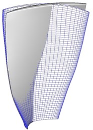
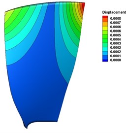
Table 1The material property of titanium alloy TC4
Density (kg/m3) | 4480 |
Poisson’s ratio | 0.33 |
Elastic modulus (GPa) | 109 |
Table 2The frequency of the first-order torsional mode
Model | 1T natural frequency (Hz) |
Tip gap 1 | 1760.6370 |
Tip gap 2 | 1765.8550 |
Tip gap 3 | 1773.6440 |
Tip gap 4 | 1781.5120 |
Tip gap 5 | 1786.8530 |
Tip gap 6 | 1792.2700 |
4. Flutter analysis
For steady simulation of the flow field of Tip gap 1-6, the inlet boundary is given sea level atmosphere and axial inflowing condition. The compressor pressure ratio characteristics shown in Fig. 2 can be calculated by adjusting the outlet back pressure. It can be seen that as the tip gap increases, the stable margin is more affected, resulting in the stalls of Tip gap 4-6 before reaching the design pressure ratio of 1.63. Therefore, this working point of 120 kpa back pressure is selected as the reference condition so that the research on aerodynamic damping under different tip gap sizes is comparable.
Fig. 3 shows the variation of the aerodynamic damping coefficient with the nodal diameter for different tip gap sizes under the first-order torsional mode. The aerodynamic damping of Tip gap 1-6 is greater than 0, indicating that the blade has no flutter risk. The aerodynamic damping at large inter-blade phase angles are quite different. Nevertheless, with the decrease of the nodal diameter, the six curves gradually approach and reach the minimum aerodynamic damping state at ND = –3. In Fig. 4 the relationship between the aerodynamic damping coefficient and the tip gap size of Tip gap 1-6 in the first-order torsional mode can be depicted as a parabolic curve. The medium clearance case Tip gap 3 has the lowest aeroelastic stability, and its aerodynamic damping coefficient is 7.13 % lower than that of clearance free scheme. The maximum clearance scheme Tip gap 6 has the highest aeroelastic stability. Its aerodynamic damping coefficients are 4.62 % and 12.67 % higher than that of Tip gap 1 and Tip gap 3, respectively.
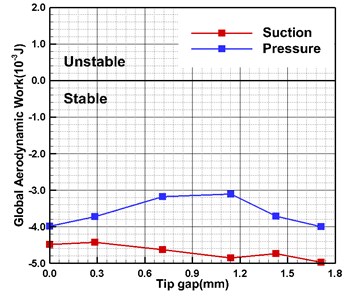
Fig. 5 is the variation curve of the aerodynamic work on the blade surface with different tip gap sizes. When the blade vibrates in the first-order torsional mode, the negative aerodynamic work intensity on the suction surface increases basically with the increase of the gap size. The relationship between the negative work of the pressure surface and the clearance shows a parabolic-like distribution, and the minimum value appears in the medium clearance scheme Tip gap 4. The negative work intensity on this surface is lower than the suction surface under all clearance cases. Due to the distribution characteristics of the two surfaces, the relationship between the aerodynamic damping and tip gap size is shown in Fig. 4.
Fig. 2Pressure ratio characteristics of Rotor67
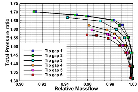
Fig. 3Variation of aerodynamic damping with nodal diameters
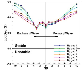
Fig. 4Variation of minimum aerodynamic damping with tip gap size
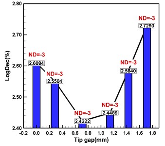
Fig. 5Variation of accumulated work on blade surface with tip clearance
The vibration amplitude of the blade tip is relatively high, and the leakage flow has a prominent influence on the local flow. Fig. 6 shows the distribution of the time-averaged static pressure and aerodynamic work with chord length at 98 % of the blade height. Between the suction leading edge and 30 % chord, the large tip clearance leads to a local “unloading” of the static pressure, and the negative work of Tip gap 5 and Tip gap 6 is significantly enhanced in this region. In addition, the difference in the distribution of aerodynamic work is mainly caused by the change of the shock wave shape, which is also reflected in the distribution of static pressures. For the pressure surface, although the impact of tip gap size on the shock intensity and position is significant, the shock oscillation on the surface does not induce a large aerodynamic work. As such, the aerodynamic work near the shock region under different clearance schemes has little difference. The influence of leakage flow on the aerodynamic work distribution is mainly manifested in the vicinity of the leading and trailing edges. From Tip gap 1 to Tip gap 6, the negative work intensity near the trailing edge gradually increases with the increase of the clearance. The change of the aerodynamic work at the leading edge is relatively complex.
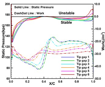
Fig. 7 is the distribution of the phase and amplitude of the first-order unsteady pressure at 98 % leaf height with chord length. Under the large clearance case, the high static pressure oscillation near the suction leading edge corresponds to the static pressure unloading area. The local leakage flow not only affects the time-averaged flow field, but also has a prominent effect on the unsteady pressure oscillation induced by the blade vibration. The blade locally contributes more positive damping, so that the negative work intensity of the damping blade vibration on this surface is significantly improved. The amplitude and phase difference of the pressure oscillation near the trailing edge is the result of the impact of the shock wave and leakage flow. For the pressure surface, since the shock wave is close to the torsional pitch diameter, the difference in the leakage flow intensity leads to a large difference in the amplitude and phase of the pressure response near the 40 % chord length. The local vibration amplitude is small, resulting in no significant difference in the local aerodynamic work.
Fig. 6Time-averaged static pressure and aerodynamic work at 98 % blade height with chord length
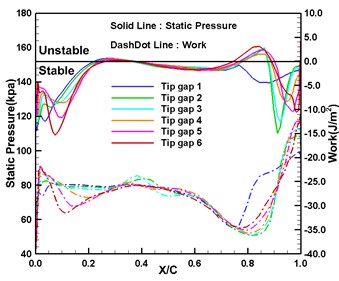
a) Suction surface
b) Pressure surface
Fig. 7First-order unsteady pressure phase and amplitude with chord length at 98 % blade height
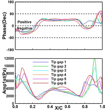
a) Suction surface
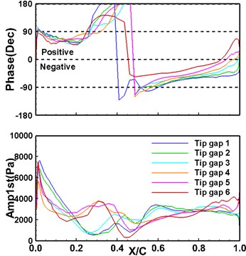
b) Pressure surface
5. Conclusions
In this paper, the influence of different tip gap sizes on the blade aerodynamic damping coefficient was numerically investigated. The aerodynamic work distribution on the blade surface and the relationship between the first-order unsteady pressure response and the clearance scale were analyzed. Related conclusions are as follows:
1) With the increase of tip gap size, the minimum aerodynamic damping coefficient of the blades first decreases and then increases with a similar parabolic distribution. The most dangerous case of aeroelastic stability is at medium tip gap size and reducing tip gap size as much as possible is beneficial to balance the aeroelastic stability and aerodynamic performance.
2) The aerodynamic work of different blade surfaces varies due to different tip gap sizes. The negative aerodynamic work of the suction surface increases slowly with the increase of gap sizes. The negative aerodynamic work intensity on the pressure surface varies sharply with respect to gap sizes, and the variation law is similar to that of the blade aerodynamic damping.
3) The region where the leakage flow has an obvious effect on the time-averaged flow field near the blade tip exactly corresponds to the region where the amplitude and phase of the first-order unsteady pressure fluctuation are significantly dissimilated due to different tip gap sizes, then the comprehensive effect of the leakage flow on the time averaged and unsteady flow fields is the main reason for the difference in blade aerodynamic damping.
References
-
H. Li, Q. Zheng, Z. Chen, Y. Duan, B. Jiang, and E. Benini, “The role of radial secondary flow in the process of rotating stall for a 1.5-stage axial compressor,” Aerospace Science and Technology, Vol. 115, No. 3, p. 106752, Aug. 2021, https://doi.org/10.1016/j.ast.2021.106752
-
X. Mao and B. Liu, “Investigation of the casing groove location effect for a large tip clearance in a counter-rotating axial flow compressor,” Aerospace Science and Technology, Vol. 105, No. 2, p. 106059, Oct. 2020, https://doi.org/10.1016/j.ast.2020.106059
-
D. L. Bell and L. He, “Three dimensional unsteady flow around a turbine blade oscillating in bending mode – an experimental and computational study,” in Unsteady Aerodynamics and Aeroelasticity of Turbomachines, Dordrecht: Springer Netherlands, 1998, pp. 53–65, https://doi.org/10.1007/978-94-011-5040-8_4
-
A. J. Sanders, K. K. Hassan, and D. C. Rabe, “Experimental and numerical study of stall flutter in a transonic low-aspect ratio fan blisk,” Journal of Turbomachinery, Vol. 126, No. 1, pp. 166–174, Jan. 2004, https://doi.org/10.1115/1.1645532
-
X. Huang, L. He, and D. L. Bell, “Effects of tip clearance on aerodynamic damping in a linear turbine cascade,” Journal of Propulsion and Power, Vol. 24, No. 1, pp. 26–33, Jan. 2008, https://doi.org/10.2514/1.25174
-
H. Yang, L. He, and Y. Wang, “Experimental study on aeroelasticity in linear oscillating compressor cascade. part Ⅱ: tip-clearance effect,” (in Chinese), Acta Aeronautica et Astronautica Sinica, Vol. 29, No. 4, pp. 804–810, 2008.
-
F. M. Besem and R. E. Kielb, “Influence of the Tip Clearance on a Compressor Blade Aerodynamic Damping,” Journal of Propulsion and Power, Vol. 33, No. 1, pp. 227–233, Jan. 2017, https://doi.org/10.2514/1.b36121
-
M. M. Zhang, S. B. Li, A. P. Hou, and S. Zhou, “A review of the research on blade flutter in turbomachinery,” (in Chinese), Advances in Mechanics, Vol. 41, No. 1, pp. 26–38, Jan. 2011.
-
K. Ekici and K. C. Hall, “Nonlinear analysis of unsteady flows in multistage turbomachines using harmonic balance,” AIAA Journal, Vol. 45, No. 5, pp. 1047–1057, May 2007, https://doi.org/10.2514/1.22888
-
X. Zhang, X. Q. Huang, H. M. Zhang, and Y. C. Chen, “Effects of shock wave on blade flutter characteristics in transonic fan,” (in Chinese), Journal of Propulsion Technology, Vol. 37, No. 3, pp. 411–418, 2016, https://doi.org/10.13675/j.cnki.tjjs.2016.03.002
About this article

This study was co-supported by the Science and Technology R&D Program of Henan Province of China (192102210272, 202102210151, 222102210050), the Key Scientific Research Project of Henan Higher Education Institutions of China (20A590002) and the Youth Talent Support Project of Henan Province (2021HYTP017). The authors also wish to thank them for their financial support.
