Abstract
In order to study the effect of speed matching on behavior of tip clearance flow and its possible link to stall inception in counter-rotating fan, the Reynolds-averaged Navier-Stokes equations are solved by the numerical method in conjunction with a SST turbulence model, the effect of speed matching on performance and stability margin are investigated, so are the difference of the tip clearance flow in different speed matching. Furthermore, the effect of speed matching on behavior of tip clearance flow and its possible link to stall inception are investigated. Research results show that: when the rotational speed of Rotor 2 is less than that of Rotor 1, with the decrease of rotational speed of Rotor 2 has no notable effect on tip clearance flow fields of the two rotors, therefore offset of stalling boundary is minor and strong blockage effect is observed in Rotor 1; when the rotational speed of Rotor 1 is less than that of Rotor 2, decrease of rotational speed of Rotor 1 show significant effect on the two rotors, which leads to major offset of stalling boundary, tip leakage flow performance of Rotor 1 improved, while that of Rotor 2 weakened and large blockage area occurs. By comparison, speed variation of Rotor 1 has more effect on stalling boundary of counter-rotating fan.
1. Introduction
A counter-rotating fan consists of two counter-rotated rotors, driven by two electro motors, which eliminates the requirement of guide vanes. It has been widely used in industry, transportation and other fields due to its advantages such as large load, lightweight, compact structure, etc. The performance characteristics of the counter-rotating fan differ from a conventional fan due to different aerodynamic layouts, which are complex issues caused by direct counter rotation of two rotating rotors and stability margin problems determined by the aerodynamic instability [1].
Since 1988, the influencing factors of counter-rotating fan performance have been conducted experimental researches by some researchers [2-4], finding the apparent impacts of the speed ratio on counter-rotating fan performance and stability margin; it is also observed that the front rotor can be operated entirely out of the rotating stall region with rotors at even speed combination. The counter-rotating fan is corresponded to the low speed compressor with low pressure head. With the development of computational fluid dynamics in recent years, the impact of speed ratio on counter-rotating fan/compressor performances has been studied in detail, mainly including performance changes and generation mechanism of the counter-rotating fan and two rotors under different speed ratios [5-8].
It is well-known that the fan performance is significantly affected by the tip leakage flow, which is an important factor for the increased internal flow loss, deteriorated flow field and even stall [9-11]. Therefore, the in-depth study of tip flow has been a hot but difficult point. By means of experiments and numerical simulation, considerable researches have been conducted concerning tip leakage flow field of rotors [12-17], the mechanism of tip clearance flow was elucidated. The numerical calculation is carried out by Hoying [18] and Vo [19] through using multiblade- and single-blade- passage three-dimensional computations, so as to explore the relationship between the tip leakage flow and stall inception. As found by Vo, the incoming/tip-clearance flow interface is aligned with the rotor leading edge plane at the blade tip, tip-clearance backflow of one blade moves across the blade passage into the neighboring passage by passing around the trailing edge. At the same time, the stall inception can be predicted by the single-blade-passage calculations verified by Vo. Currently, though gratifying progress has been made in recent researches concerning tip leakage flow field, better explanation for many problems is still inadequate due to the complexity of itself and its influenced factors.
Owing to the strong interaction of two rotors of counter-rotating fan, the global characteristics will be affected by the rotational speed change of a rotor, thus inevitably impact the characteristics of tip leakage vortex and thereby affect the fan performance and stability margin. As indicated from previous literature, few researches have been made concerning the impact of speed matching on tip leakage flow (vortex). Therefore, in-depth research and analysis of characteristics of tip leakage flow (vortex) at different speed matching are necessary. Numerical simulation method is applied in this paper to carry out steady flow research of a counter-rotating fan, the impact of speed ratio (: 1, : 1, : 1) on the fan performance and stability margin is analyzed, and researches on characteristics of tip clearance flow field are conducted under the near-stall flow condition.
2. Introduction of research object and tip leakage flow
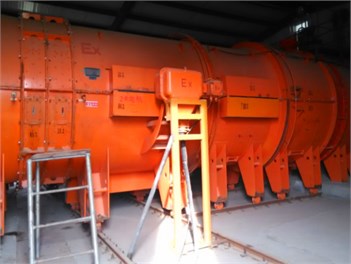
The research object of this paper is a FBCDZ-No. 20 counter-rotating fan. It consists of a clockwise-rotating first rotor (Rotor 1) and an anticlockwise-rotating second rotor (Rotor 2), with the hub ratio of 0.618. Rotor 1 and Rotor 2 had 19 and 17 blades, respectively. An experiment has been conducted on the counter-rotating fan, which is shown in Fig. 1, and the specific design parameters of the fan are shown as Table 1. Two AC induction motors of 185 KW with separate variable frequency drives are used to drive the rotors at different speed combinations. At the inlet of and outlet of , two pitot probe rakes comprising eight pitot tubes (1 mm in diameter for each tube) are employed to measure the total pressure. The probe was calibrated for non-nulling mode at an angular interval of 2°.
Fig. 1The counter-rotating fan for testing
The reason for setting the tip clearance of the axial fan is avoiding the friction between the rotating blade and the wall of the casing. The tip leakage flows the pressure difference between the both sides of the blade at the tip clearance position, usually accompanied by tip leakage vortex exists. The tip leakage flow can cause leakage loss and blockage, thereby reducing the efficiency and stability margin of the axial fan, also is a major source of aerodynamic noise. Vo used single-blade-passage computations to find that when the spike stall initial disturbance occurs inside the compressor, the flow response suggests a spillage of tip-clearance flow to the adjacent blade passage ahead of the rotor leading edge and below the blade tip's radius, as shown in Fig. 2(a), the incoming flow/tip-clearance flow interface lies parallel to the rotor leading-edge plane, in addition, Fluid originating from the tip-clearance region of one blade moves across the blade passage into the neighboring passage by passing around the trailing edge, as shown in Fig. 2(b).
Table 1Design parameters of the counter rotating axial fan
Design parameter | Rotor 1 | Rotor 2 |
Design speed (rpm) | –980 | 980 |
Outer diameter (mm) | 2000 | 2000 |
Blade number | 19 | 17 |
Chord (tip/mid/hub) (mm) | 195.1 / 210.1 / 223.5 | 194.8 / 209.7 / 222.6 |
Design mass flow (kg/s) | 80 | 80 |
Tip clearance (mm) | 5 | 5 |
Fig. 2The tip leakage flow feature near spike stall
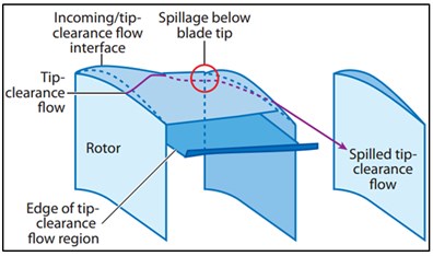
a) Leading-edge tip-clearance flow spillage below the blade tip
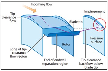
b) Backflow of tip-clearance fluid below the blade tip
3. Simulation methodology
3.1. Numerical model
ANSYS CFX is used to solve the three-dimensional compressible Reynolds-averaged Navier-Stokes equations. The finite volume method is employed as the numerical method. The turbulence model of Shear Stress Transport model is applied, referred to as SST model, which is combined with advantages of - turbulence model in terms of simulating the near-wall boundary layer and characteristics of - turbulence model concerning small dependence towards far-field boundary conditions [20], thus having greater prediction accuracy pertaining the tip leakage flow.
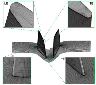
A composite grid system with structured grids was used to simulate the tip leakage flow field accurately, with the total number of 2.9 million grids, as shown in Fig. 3. The computing meshes are divided into domains of Rotor 1 and Rotor 2. The numbers of stream wise, span wise and pitch wise grid nodes of both Rotor 1 and Rotor 2 are 123×85×91. To improve the quality of grids, O-block grid is applied on the plane area of blades, H-block grid is employed by the inlet and outlet and mainstream area, and butterfly grid topology is used in the clearance region. A total of 29 grid nodes in the span wise direction are existed in the clearance, with the first layer of mesh wall thickness of 0.003 mm, gives 2 at the walls, thus meeting the requirements of turbulence model.
In order to verify the gird independence, 1.2 million grids are taken as the starting point, and 5 computations with different grid nodes are carried out from 1.2 million, 1.8 million, 2.9 million, 3.4 million and 3.8 million respectively. The distribution densities of the 5 different grid nodes are similar, which are mainly used for encryption. As indicated from the calculation, fan performance parameters are no longer sensitive to grid nodes when the number of nodes is more than 2.9 million. Therefore, 2.9 million grid nodes are applied for the calculation in the paper under comprehensive consideration of computational accuracy and time.
No-slip and adiabatic conditions are applied to all wall surfaces; the total temperature and total pressure of standard atmosphere as well as axial inflow are specified as the inlet boundary condition; while the static pressure is specified at the outlet assuming radial equilibrium. The stage method is used to process the interface. Due to the extreme complexity of fan flow field at near-stall point, so far there is no accurate numerical simulation method to capture the fan stall point. Therefore, at current stage, numerical divergence point is applied as fan stall point by most researchers.
Fig. 3Computational grid
3.2. Research scheme
The impact of speed ratio on fan performance, stability margin and tip flow field of near-stall points are emphasized in this paper. The speed triangle of counter-rotating fan is shown in Fig. 4. Rotor 1 and Rotor 2 are influenced by flow rate. Reduced flow rate leads to decreased axial velocity (), so that the angle between the relative velocity () and the blade inlet increases, resulting in an increase in the incidence airflow angle. When the blade rows work in a large incidence angle, because of some interference in the flow field, it will cause the instantaneous flow separation in one or several blade passages and cause the blockage, this separation disturbance develops rapidly, may develop into a large rotating stall cells within a very short period of time. Therefore, at near-stall point, the blade attack angle increases are relatively larger due to the declined axial speed, and it can be declined because of the reduction of tangential velocity , thereby improving working conditions.
Fig. 4Velocity triangles. Fluid is flowing from left to right
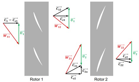
Table 2Rotating speed scheme
Number | (rpm) | (rpm) | Speed ratio (:) |
1 | 980 | 980 | 1 |
2 | 980 | 900 | 0.92 |
3 | 980 | 820 | 0.84 |
4 | 980 | 740 | 0.75 |
5 | 900 | 980 | 1.09 |
6 | 820 | 980 | 1.20 |
7 | 740 | 980 | 1.32 |
The design speed ratio is set as the benchmark, 6 different designs varying in speed ratio are presented in Table 2. The design speed ratio is designed in program 1, : 1; the rotational speed of Rotor 2 is gradually decreased in program 2-4 while the rotational speed of Rotor 1 is remained consistent at 980 rpm, : 1; and the rotational speed of Rotor 1 is gradually decreased in program 5-7 while the rotational speed of Rotor 2 is remained consistent at 980 rpm, : 1.
4. Results and discussion
4.1. Validation of simulation
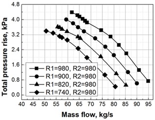
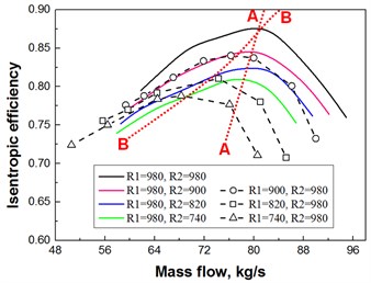
The performance characteristic curves of numerical simulation and experiment are shown in Fig. 5. The results of the simulations show a good agreement with experimental data. In the first half of total pressure rise characteristic diagram, the numerical simulation result is slightly higher than the total pressure rise obtained from experiments; and in the second half of efficiency characteristic diagram, the experimental result reduces rapidly; the numerical simulation result is slightly greater than the experimental result in terms of flow values corresponded by stall points. As shown in Fig. 5, point A is the stall point captured by numerical simulation, and point B is the computational point at the step before that of point A, with the backpressure difference of 100 Pa. Thereafter, researches of the near-stall point are all developed for point B due to its vicinity of stall and its relative stable calculation.
Fig. 5Performance map of the test fan
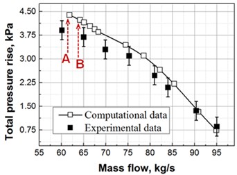
a) Total pressure rise versus mass flow
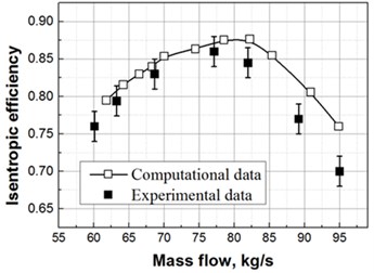
b) Isentropic efficiency versus mass flow
4.2. Effect of speed ratio on performance and stability margin
Tip leakage flow played a major impact on fan performance and stability margin. The characteristic curve regarding total pressure rise of the fan was given under different speed ratios, as shown in Fig. 6. It is indicated that under different speed ratios, the stall flow is offset towards small flow range and the stable operating range is reduced along with the decreasing speed ratio of Rotor 1 or Rotor 2, the stall flow is offset towards small flow range, the stable operating range of the fan is reduced, and furthermore, the fan pressure rise was gradually declined at the same flow rate. However, the characteristic curves of : 1 and : 1 are compared, finding that significantly greater offset amplitude towards small flow is presented in the stall flow at : 1.
The efficiency characteristic curve under different speed ratios is displayed in Fig. 7, and the stability margin characteristics are consistent with that in Fig. 6. With the declined rotational speeds of Rotor 1 and Rotor 2, the fan efficiency is gradually decreased at the same flow rate, and the maximum efficiency point is offset towards the small flow rate. Red lines A-A and B-B in the figure are link line of highest efficiency points of speed ratios : 1 and : 1, respectively. With the reduced rotational speed, the offset amplitude concerning the maximum efficiency points of : 1 is lesser, while that of : 1 is greater. In addition, in the points after maximum efficiency point in efficiency characteristic curve, faster declining trend of : 1 is shown.
Therefore, as analyze from the perspective of the fan performance and stability margin, the purpose of delay stall can be achieved through the changes of speed ratio. And the application of speed triangle can be understood as that in the near-stall flow range, the inlet air attack angle of corresponding rotors is reduced with the declining rotational speed of Rotor 1 or Rotor 2, thereby improving its flow field. Since the essential existence of several stall groups rotating around blade surfaces, the rotating stall phenomenon is thus a strong three-dimensional flow phenomena. Therefore, further analysis through numerical simulation of flow field is necessary.
Fig. 6Counter-rotating fan characteristic curves of total pressure
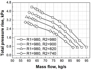
a) Speed ratio : 1
b) Speed ratio : 1
Fig. 7Counter-rotating fan characteristic curves of isentropic efficiency
4.3. Effect of speed ratio on characteristics of tip clearance flow field
Tip leakage vortex plays a key role in stall inception, which has become a consensus. As found in many researches [15, 21-23], unsteady fluctuations are existed in the tip leakage flow field of most fans/compressors under the near-stall states, tip leakage vortex breaks under certain conditions, but disagreements are still appeared in mechanisms of unsteady flow phenomenon in tip regions. As demonstrated in numerical simulation of unsteady flow by Hu [24], weak unsteady character is stayed in the near-stall points of the low speed fan, which is basically consistent with the result obtained from the steady calculation. Therefore, steady results are selected in this paper for the analysis.
4.3.1. Comparative of tip clearance flow field under different conditions
When the condition is : 1, the characteristics of tip clearance flow field are firstly analyzed at the design point and near-stall points, as shown in Fig. 8. The tip clearance flow streamline of Rotor 1 and Rotor 2 is displayed in Fig. 8(a), and the circumferential average absolute vorticity contour is presented in Fig. 8(b). The black and red lines in the figure represented tip streamlines at 0.2 h and 0.8 h, respectively: h is the tip clearance heights, 0 h is the blade tip and 1 h is the casing. And the absolute vorticity was defined as:
where, and represented the mode of absolute vorticity and rotational angular velocity, respectively. The larger value of absolute vorticity is, the higher strength of the clearance leakage vortex would be.
As known from the streamline diagram, tip leakage vortex is appeared in Rotor 1 and Rotor 2 under the design condition, with the vortex core in the form of concentrated vortex, which is appeared in the blade leading edge. Tip leakage vortex streamlines are rolled tightly and spirally. With flow reduce to near stall point, the streamline is changed apparently, the upstream incoming flow and leakage flow of Rotor 1 are rolled at the leading edge, and the fluids in stream wise direction are almost parallel with the leading edge of plane of blades, which is consistent with the research of Vo [19]. Meanwhile, the leading edge streamline of Rotor 1 is in diffusion shape, and the streamline of Rotor 2 spiral degree becomes weak. In addition, due to the relative motion between the rotor and casing, the tip leakage vortex is significantly influenced by the drag action of viscous force in wall boundary layer, which led to the nearly circumferential leakage streamline close to the wall, thus eventually resulting in the occurrence of secondary leakage.
As found from circumferential average contour of absolute vorticity, at the design point, the tip leakage vortex is appeared in the upstream and middle regions of chord length, while at the near-stall point, the tip leakage vortex is emerged in the blade leading edge, which is consistent with the above streamline result. The flow from the design point to the near-stall point, high vorticity region within the tip clearance is significantly increased along both radial and flow direction, while the vorticity within the casting area is not changed significantly. Therefore, the tip leakage vortex is the main reason of fan stall.
Fig. 8Behavior of the tip leakage flow at two representative operating points
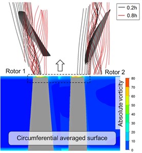
a) Peak efficiency point
b) Near stall point
4.3.2. Analysis of tip clearance flow field under different speed ratios
To study the effect of speed ratio on tip clearance leakage flow, the flow characteristics of tip clearance flow field at near-stall point (Fig. 5, point B) under different speed ratios are studied as below.
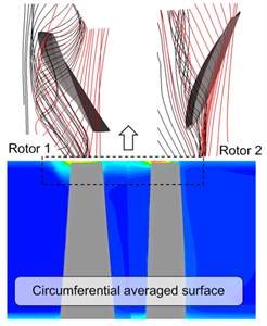
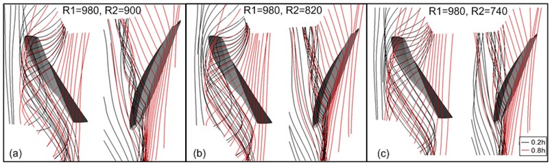
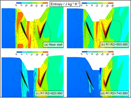
The tip clearance flow streamlines under different speed ratios are shown in Fig. 9 and Fig. 10. The condition of : 1 (Rotor 1 of fixed speed and Rotor 2 of gradual decreasing speed) is shown in Fig. 9 and the condition of : 1 (Rotor 2 of fixed speed and Rotor 1 of gradual decreasing speed) is displayed in Fig. 10. Black and red lines in the figure represented tip streamlines at 0.2 h and 0.8 h, respectively. The static entropy contour and casting wall static pressure distribution at different speed ratios are shown in Fig. 11 and Fig. 12. The condition of : 1 is shown in Fig. 11 and : 1 is displayed in Fig. 12.
With the condition of : 1 in Fig. 9, the rotational speed of Rotor 1 is remained constant, and the leakage flow streamline is shown little changes on Rotor 1; meanwhile, the spiral degree of tip clearance streamline of Rotor 2 is reduced slightly along with the decreasing rotational speed of Rotor 2. As seen from the static entropy contour in Fig. 11, an obvious interface, including dramatic entropy gradient changes in the direction parallel with the leading edge plane, between high and low entropy values is existed in the leading edge of Rotor 1, which is the interface of mainstream and leakage flow. A similar interface is also appeared in the leading edge of Rotor 2, namely the interface of upstream incoming flow and tip leakage flow of Rotor 2. With the decreasing rotational speed of Rotor 2, no significant changes are shown in the interface of Rotor 1 leading edge, while the entropy gradient in the interface of leading edge of Rotor 2 is weakened gradually. When the condition is : 740:980, the entropy gradient of interface is relatively small, indicating a better balance reached between the mainstream momentum and tip leakage flow momentum of Rotor 2. As found from static pressure distribution in Fig. 11, an obvious pressure trough is appeared in the blade suction surface side. It was indicated from Furukawa’s research that the pressure trough of casting wall was corresponding to characteristics of the tip leakage vortex. The pressure trough of Rotor 1 declines rapidly in the stream wise direction, and that of Rotor 2 is very apparent in stream wise direction. Along with the reduction of rotational speed of Rotor 2, no obvious changes of pressure trough of Rotor 1 and Rotor 2 is shown in the leakage flow direction, thus indicating the insignificant changes regarding characteristics of tip leakage vortex.
Fig. 9Tip clearance flow at speed ratio R2:R1< 1: a) R1:R2= 980:900, b) R1:R2= 980:820, c) R1:R2= 980:740
Under the condition of : 1 in Fig. 10, the streamlines of Rotor 1 and Rotor 2 are changed significantly. When the rotational speed of Rotor 1 is declined, the originally diffused streamline at the leading edge of Rotor 1 is changed to the tight spiral, and the red streamline at the side of the wall is transferred from circumferential to the stream wise direction, thus indicating the improvement of flow field characteristics of Rotor 1; meanwhile, the streamline form of Rotor 2 is altered from the spiral to the diffusion due to the impact of speed ratio. The static entropy contour of Rotor 1 in Fig. 12 is changed significantly, and the reduced rotational speed of Rotor 1 caused the high-entropy gradient interface in its leading edge to move inside the channel; the entropy values in leading edge of Rotor 2 have always been existed. As found from static pressure distribution, if the rotational speed of Rotor 1 is reduced, the pressure trough on the wall of Rotor 1 is becoming clear gradually, and the angle between vortex core track and chord length is significantly reduced; and meanwhile, the pressure trough on the wall of Rotor 2 is attenuated gradually, and the angle between vortex core track and chord length is decreased slightly.
Fig. 10Tip clearance flow at speed ratio R2:R1> 1: a) R1:R2= 900:980, b) R1:R2= 820:980, c) R1:R2= 740:980
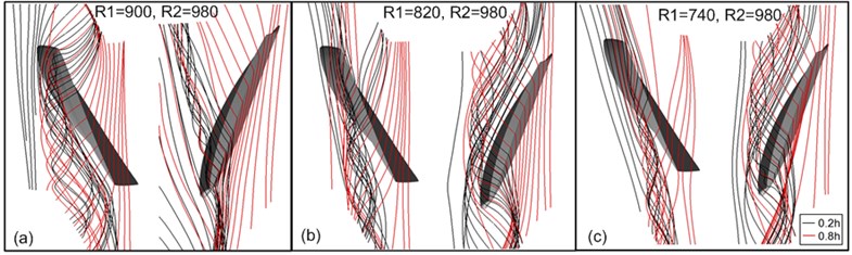
Fig. 11Static entropy contour and casting wall static pressure distribution at speed ratio R2:R1< 1: a) Near-stall point R1:R2= 980: 980, b) R1:R2= 980:900, c) R1:R2= 980:820, d) R1:R2= 980:740
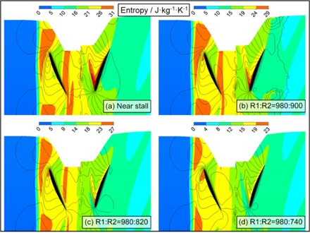
Fig. 12Static entropy contour and casting wall static pressure distribution at speed ratio R2:R1> 1: a) Near-stall point R1:R2= 980: 980, b) R1:R2= 980:900, c) R1:R2= 980:820, d) R1:R2= 980:740
Therefore, the reduction of rotor speed can, firstly, weaken the viscous force in boundary layer suffered by tip leakage vortex of the rotor; secondly, reduce the high load on the rotor, thereby improving its tip leakage flow field. It is worth noting that characteristics impact of tip leakage vortex of counter-rotating fan can be significantly differed by the changes of rotational speeds of Rotor 1 and Rotor 2. Hence, characteristics of tip leakage vortex of counter-rotating fan are given further analysis.
4.3.3. Characteristics of tip leakage vortex under different speed ratios
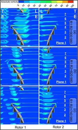
The absolute vorticity contour under different speed ratios is shown in Fig. 13, and the distribution of total pressure loss coefficient in stream wise direction under different speed ratios is shown in Fig. 14, respectively. In the figure, the cross section (Plane 1, Plane 2, Plane 3, ...) is approximately perpendicular to the tip leakage vortex direction. LE indicates the leading edge of the blade and TE expresses the rear edge of the blade. The definition of absolute vorticity had been given in Eq. (1).
Fig. 13Stream wise absolute vorticity distributions on crossflow planes
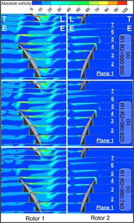
a): 1
b): 1
Tip leakage vortex core is corresponding to the concentrated area of vorticity. With : 1 in Fig. 13(a), a clear concentrated area of vorticity can be seen in Plane 1 of the Rotor 1. However, affected by the strong viscous force in the boundary layer, the concentrated area of vorticity is diffused apparently and vigorously from Plane 2. That same was to that from Plane 3, 4, 5, 6. Since the mainstream is overflowed in the leading edge, a series of vortex patches with low absolute vorticity magnitude are appeared in the leading edge of the plane. Rotor 2 is changed simultaneously with Rotor 1. Regarding Rotor 2, though the absolute vorticity of tip leakage vortex is gradually weakened in the stream wise direction at the same time, the concentrated area of vorticity corresponded by vortex core can be clearly observed from Plane 1 to Plane 4. Along with the gradually decreasing rotational speeds of Rotor 2, small changes regarding the absolute vorticity characteristics are presented in Rotor 1 and Rotor 2, which is consistent with the above analysis in Fig. 9 and 11.
As can be seen from Fig. 13(b), at the condition of : 1, along with the decreasing rotational speed of Rotor 1, significant changes are appeared in the absolute vorticity contour of Rotor 1; a series of obvious concentrated area of vorticity are appeared in the blade passage; and the angle between vortex core track and chord length is decreased, which is corresponding to the static pressure distribution on the wall in Fig. 11. As indicated from the vorticity distribution contour of Rotor 2, when the speed ratio is changed to : 820:980 from : 900:980, the absolute vorticity distribution pattern is appeared abruptly in the blade passage of Rotor 2, and the concentrated area of vorticity is significantly diffused, which is no longer evident in Plane 4.
Total pressure loss coefficient in Fig. 14 is defined as:
wherein, represented local total pressure, the total pressure loss coefficient in the numerical range greater than zero is only shown in the figure.
Fig. 14Total pressure loss distribution on crossflow planes
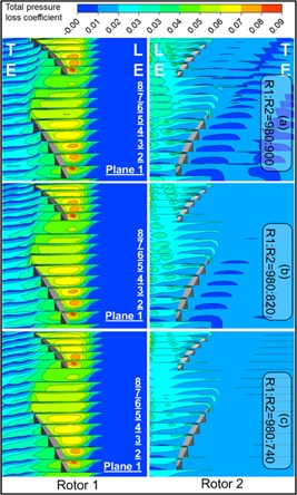
a): 1
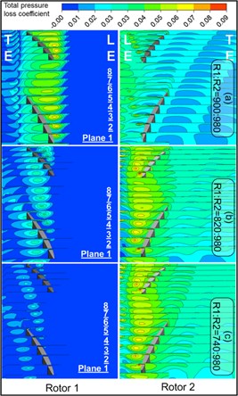
b): 1
At the condition of : 1 in Fig. 14(a), the total pressure loss of Rotor 1 is dramatic in the streamwise direction, whose scope is developed in the streamwise and radial directions until covering the entire blade passage. High loss region means the accumulation of low-energy fluid on the wall, and severe blocking effect is caused by greater high loss area, thus resulting in significant blocking impact of Rotor 1. And at the speed ratio of : 1, certain degree of total pressure losses is existed in the leading edge of plane of Rotor 2. With the decreasing rotational speed of Rotor 2, the total pressure losses of Rotor 1 and 2 are only relieved mildly. At the condition of : 980:740, the mixing phenomenon in Rotor 2 channel is apparent, which is corresponding to the smaller entropy gradient of Rotor 2 in Fig. 11.
At the condition of : 1 in Fig. 14(b), the scope and strength of total pressure losses on Rotor 1 are declined rapidly with the decreasing rotational speed of Rotor 1, while the scope and strength of total pressure losses in the entire tip area of Rotor 2 are increased. Therefore, the blocking effect of Rotor 1 can be improved by such speed ratio, which could, however, aggravate the blocking effect of Rotor 2.
Speed ratio plays an important influence on the characteristics of tip leakage vortex. And characteristics of tip leakage vortex can be varied through the individual change regarding rotational speeds of Rotor 1 or Rotor 2. Compared with the speed ratio of : 1, the tip leakage vortex at the speed ratio of : 1 is suffered from stronger impact. In the characteristic curve, it is expressed by the offsetting stall point towards points with small flow rate, showing greater amplitude. Moreover, a rotor with high rotational speed has more severe corresponding blocking degrees in the tip region under different speed ratios.
5. Conclusions
1) In terms of fan performance and stability margin, general good agreement is shown between the steady calculation result and the actually measured data. When the speed matching changes and with the increase of rotational speed difference between two rotors, both total pressure rise and efficiency of the fan reduce at the same flow rate, the stable operating range narrows, and the stall boundary is offset to the small flow. When the rotational speed of rotor 1 is less than that of Rotor 2, the offset degrees of both stall boundary and maximum efficiency points at the speed ratio are more apparent.
2) With : 1 and near-stall flow, along with the decreasing the rotational speed of Rotor 2, the characteristics of tip clearance flow field of Rotor 1 are of little changes along with the reducing speed ratio. An interface between the mainstream and tip leakage flow exists in the leading edge of Rotor 1, and tip leakage vortex of Rotor 1 diffuses dramatically in the stream wise direction, thus leads to a large area of strong total pressure loss and powerful blocking effect. The characteristics of tip clearance vortex of Rotor 2 present no significant changes, maintaining a clear structure of concentrated vortex. However, a better balance is reached between the mainstream momentum and tip leakage flow momentum of Rotor 2, leading to dramatic blending between the tip leakage flow and the mainstream.
3) With : 1 and near-stall flow, along with the decreasing the rotational speed of Rotor1, the concentrated vortex characteristics gradually recover in the tip leakage vortex of Rotor 1, the tip leakage flow field improves significantly and the blocking effect is weakened. The tip leakage flow field of Rotor 2 deteriorates seriously along with its increasing speed ratio, an interface between the mainstream and tip leakage flow with greater entropy gradient is appeared in the leading edge, and significantly high total pressure loss region is shown in the blade tip range, resulting in severe blocking effect.
4) As indicated from the characteristics of tip clearance flow field under different speeds, the rotational change of Rotor 1 exerts a great influence on the characteristics of tip clearance flow field of two rotors, while the rotational change of Rotor 2 only brought about certain impact on the characteristics of tip clearance flow field of Rotor 2. Therefore, a greater impact is played from the rotational speed of Rotor 1 on the stall boundary of the counter-rotating fan.
References
-
Tan C. S., Day I., Morris S., et al. Spike-type compressor stall inception, detection, and control. Annual Review of Fluid Mechanics, Vol. 42, Issue 42, 2015, p. 275-300.
-
Sharma P. B., Jain Y. P., Pundhir D. S. A study of some factors affecting the performance of a contra-rotating axial compressor stage. ARCHIVE Proceedings of the Institution of Mechanical Engineers Part a Power and Process Engineering, Vol. 202, Issue 11, 1988, p. 15-21.
-
Sharma P. B., Adekoya J. L. A review of recent research on contra-rotating axial flow compressor stage. ASME International Gas Turbine and Aeroengine Congress and Exhibition, 1996, p. V001T01A073.
-
Roy B., Ravibabu K., Rao P. S., et al. Flow studies in ducted twin-rotor contra-rotating axial flow fans. ASME International Gas Turbine and Aeroengine Congress and Exposition, 1992 p. V001T01A131.
-
Mistry C., Pradeep A. M. Effect of variation in axial spacing and rotor speed combinations on the performance of a high aspect ratio contra-rotating axial fan stage. Proceedings of the Institution of Mechanical Engineers, Part A: Journal of Power and Energy, Vol. 227, Issue 2, 2013, p. 138-146.
-
Nouri H., Ravelet F., Bakir F., et al. Design and experimental validation of a ducted counter-rotating axial-flow fans system. Journal of Fluids Engineering, Vol. 134, Issue 10, 2012, p. 104504.
-
Chen Y. Y., Liu B., Xuan Y., et al. A study of speed ratio affecting the performance of a contra-rotating axial compressor. Proceedings of the Institution of Mechanical Engineers, Part G: Journal of Aerospace Engineering, Vol. 222, Issue 7, 2008, p. 985-991.
-
Gao L., Li X., Feng X., et al. Effects of rotational speed ratio on stability boundary of contra-rotating compressor. Journal of Propulsion Technology, Vol. 6, 2012.
-
Wisler D. C. Loss reduction in axial-flow compressors through low-speed model testing. Transactions of the ASME, Journal of Engineering for Gas Turbines, Vol. 107, Issue 2, 1985, p. 354-363.
-
Adamczyk J. J., Celestina M. L., Greitzer E. M. The role of tip clearance in high-speed fan stall. ASME International Gas Turbine and Aeroengine Congress and Exposition, 1991, p. V001T01A031.
-
Inoue M., Kuroumaru M., Yoshida S., et al. Effect of tip clearance on stall evolution process in a low-speed axial compressor stage. ASME Turbo Expo 2004: Power for Land, Sea, and Air. American Society of Mechanical Engineers, 2004, p. 385-394.
-
Inoue M., Kuroumaru M., Fukuhara M. Behavior of tip leakage flow behind an axial compressor rotor. Journal of Engineering for Gas Turbines and Power, Vol. 108, Issue 1, 1985, p. 7-14.
-
Inoue M., Kuroumaru M. Structure of tip clearance flow in an isolated axial compressor rotor. Journal of Turbomachinery, Vol. 111, Issue 3, 1989, p. 250-256.
-
Lakshminarayana B., Zaccaria M., Marathe B. The structure of tip clearance flow in axial flow compressors. Journal of Turbomachinery, Vol. 117, Issue 3, 1995, p. 336-347.
-
Furukawa M. The role of tip leakage vortex breakdown in compressor rotor aerodynamics. Journal of Turbomachinery, Vol. 121, Issue 3, 1999, p. 469-480.
-
Yu X., Liu B., Jiang H. Characteristics of the tip leakage vortex in a low-speed axial compressor. AIAA Journal, Vol. 45, Issue 4, 2007, p. 870-878.
-
Wu Y., Li Q., Chu W., et al. Numerical investigation of the unsteady behaviour of tip clearance flow and its possible link to stall inception. Proceedings of the Institution of Mechanical Engineers Part A, Journal of Power and Energy, Vol. 224, Issue 24, 2010, p. 85-96.
-
Hoying D. A., Tan C. S., Vo H. D., et al. Role of blade passage flow structures in axial compressor rotating stall inception. Journal of Turbomachinery, Vol. 121, Issue 4, 1999, p. 735-742.
-
Vo H. D., Tan C. S., Greitzer E. M. Criteria for spike initiated rotating stall. Journal of Turbomachinery, Vol. 130, Issue 1, 2008, p. 155-165.
-
Menter F. R. Two-equation eddy-viscosity turbulence models for engineering applications. AIAA Journal, Vol. 32, Issue 8, 1994, p. 1598-1605.
-
Mailach R. Rotating instabilities in an axial compressor originating from the fluctuating blade tip vortex. Journal of Turbomachinery, Vol. 123, Issue 3, 2001, p. 453-460.
-
Yamada K., Furukawa M., Nakano T., et al. Unsteady three-dimensional flow phenomena due to breakdown of tip leakage vortex in a transonic axial compressor rotor. ASME Turbo Expo 2004: Power for Land, Sea, and Air, 2004, p. 515-526.
-
Gao L., Li R., Miao F., et al. Unsteady investigation on tip flow field and rotating stall in counter-rotating axial compressor. Journal of Engineering for Gas Turbines and Power, Vol. 137, Issue 7, 2015, p. 072603.
-
Zhang C., Hu J., Wang Z. Q., et al. Numerical study on tip clearance flow structure of an axial flow compressor rotor. Acta Aeronautica et Astronautica Sinica, Vol. 35, Issue 5, 2014, p. 1236-1245.
About this article

The research work is financially supported by Natural Science Foundation of Shandong Province under No. ZR2013EEM017
Hengxuan Luan conceived the work that acquired data, played an important role in interpreting the results. Qingguang Chen revised the manuscript and performed the experiments. Liyuan Weng led to the submission. Yuanzhong Luan contributed materials tools and analysis tools. Peng Chen digested experimental data.
