Abstract
In helicopter rotorcraft design, two main approaches as passive and active control methods widely used to decline vibration. In this study passive control methods are used to reduce vibration in the helicopter rotor blade. The most common passive control devices are dynamic vibration dampers, isolators and structural distribution of the composite blades. A surrogate optimization formula is used as the objective function of vibration reduction which includes vibratory hub loads and bending moments. In optimization model, composite ply angles are design variables and spar frequency-placement, autorotation and stress conditions are constraints. As the optimization method, a hybrid solution is chosen. The gradient-based algorithms generate accurate results in trust region and heuristic methods scan very large area of solution space. Due to the aforementioned advantages, these algorithms are hybridized. As a result of the comparison of the optimization outcomes with the baseline UH-60 rotor blades, approximately 38 % vibration reduction is observed in the new design.
1. Introduction
Modern helicopters are complex dynamic systems that are exposed to vibrations and fatigues at high levels throughout their service life due to the tasks and working environments. As a result of this, vibration is one of the most important criteria to consider in helicopter rotorcraft design. Also, human discomfort and sickness, reading difficulty, ineffectiveness of weapons systems are the main outcomes of the vibration.
The helicopter rotor system provides lift and land ability to the helicopter. Helicopter design researches demonstrate that the rotor blades are the main load carrying component. In addition, the design of helicopter main rotor blade is still being a subject of discussion and research due to factors such as the variable curvature of the blade geometry, complexity of the physical conditions and the flow around a blade.
Passive and active control methods mainly encountered in reducing vibration for helicopter rotorcraft design. Active control systems have sensors, drive systems and controllers for instant feedbacks [1]. The usage of sensors, actuators and layers containing piezoelectric smart material among is quite common and researchers have focused on piezoelectric materials for vibration reduction [2-6]. On the other hand, the manufacturing of piezoelectric products is considerably expensive and complicated. Also, active control systems usually need big power requirements to generate large pitch link loads and significantly contain complexity [7].
Passive control methods such as vibration absorbers, isolators and structural distribution of materials use fewer complex approaches. Vibration absorbers and isolation devices are set for determined operating conditions and loads. Furthermore, these tools adjoin additional weight to the system and cannot reduce the vibration at the source of the main rotor. Structural distribution of materials does not add any weight to the system.
Since the mid-1950s, studies have been carried out to decrease the vibration of rotor blades, such as the placement of mass along the blade beam in helicopters. In the early 1990s, Friedmann et al. [8] used vibration reduction surrogate mathematical expression as an objective function. Also, design variables were spar geometry, non-structural mass and the placement of mass. They incorporated frequency placement and aeroelastic stability constraints into the optimization model. Lim and Chopra [9] used the same design variables. Constraints of optimization model were autorotation, frequency placement and aero-elastic limitations. Ganguli and Chopra [10] used fiber angles of composite spar walls as design variables. They have benefited from circumferentially uniform stiffness (CUS) and circumferentially asymmetric stiffness (CAS) distributions in the composite layer angles.
Ganguli [11] has preferred the stiffness matrix values of bending in transverse and longitudinal directions as design variables. The constraints of the optimization model were determined as 25 % lower and upper limits of design variables. Glaz et al. [12-13] used non-structural mass and its location, and also flanges-webs thickness’ of the spar as variables in the optimization. Constraints were autorotation, frequency and aeroelastic limitations. Since 2010, usage of failure criterion such as Tsai-Wu, maximum stress and failure mechanism based methodologies have been observed effectively in the field [14-15].
In this study, structural distribution of materials has been preferred to decrease vibration at the source and using the vibration reduction surrogate optimization formula as objective function. The formulation was created by computing an aeroelastic response code which includes Nb/rev hub loads and moments [7-13], [16-17]. Ply angles are design variables and autorotation, Tsai-Hill failure and natural frequency criterion are structural constraints.
2. Cross-sectional analysis of composite rotor blades
Berdickevsky [18] developed a variational asymptotic method (VAM) which proves that three-dimensional (3D) nonlinear elasticity analysis for beam-like structures can be considered as linear two-dimensional (2D) section analysis and nonlinear one-dimensional (1D) beam analysis. In the 1990s, Hodges and co-workers [19] developed variational asymptotic beam sectional analysis (VABS) methodology for complex compo-site blade cross-sectional analysis which is based on general finite elements and VAM.
For cross-section analysis in VABS, densities and elastic constants of materials and sectional geometry details are required. Convention of cross-sectional composite layup and angle for a box-beam is shown in Fig. 1.
Fig. 1VABS layup scheme for a box-beam [20]
![VABS layup scheme for a box-beam [20]](https://static-01.extrica.com/articles/22337/22337-img1.jpg)
The main outcomes are the 6×6 cross-sectional mass matrix, the mass per unit length, 4×4 classical stiffness matrix and 6×6 stiffness matrix. The 4×4 stiffness matrix includes extension, twist and bending deformations. For the classical beam model can be expressed as:
The 6×6 stiffness matrix not only includes mentioned deformations but also contains shear deformations. The 6×6 stiffness matrix for the generalized Timoshenko model equilibrium is given by:
The cross-sectional VABS outputs are also inputs of 1D nonlinear beam analysis programs. In this way, similar results are obtained with less time and cost than 3D non-linear elasticity analysis.
3. Dynamic analysis of composite rotor blades
As a result of VAM approach, integration of linear 2D cross-sectional analysis and nonlinear 1D beam analysis reduces the analysis time from hours to seconds by quickly and easily achieving the accuracy of detailed 3D geometrically nonlinear elasticity analysis of the rotors. Thus, researchers use integration of VABS and rotorcraft dynamic analysis methods to reach 3D analysis results by less time and computationally [19], [21-12]. The most used dynamic analysis methods of rotorcraft are RCAS, GEBT, DYMORE and CAMRAD II. Multibody modeling with rigid and elastic joints, rigid bodies, and nonlinear elastic bodies can be formed as beams, plates, and shells by DYMORE [21].
DYMORE provides it possible to treat the blade beam as a 1D curve line which is called the lifting line, given in Fig. 2. Also, mechanical responses can be received from stations assigned along the line. DYMORE modelling of rotor elements is represented in Fig. 3.
Fig. 2Representation of the box beam as a curved line in DYMORE [23]
![Representation of the box beam as a curved line in DYMORE [23]](https://static-01.extrica.com/articles/22337/22337-img2.jpg)
Fig. 3Schematic representation of rotor elements in DYMORE [23]
![Schematic representation of rotor elements in DYMORE [23]](https://static-01.extrica.com/articles/22337/22337-img3.jpg)
4. Description of the baseline UH-60 rotor blades and composite layup configurations
The rotor blades, in other words special airfoil for helicopters, ensure aerodynamic forces and moments when imposed upon a relative motion on blades surface. Structural loads and couplings occur because of aerodynamics lift and drag forces along the blade. DYMORE computes the structural loads at any selected cross-section airstations along the blade beam.
Sikorsky UH-60 Black Hawk was used for the comparative study. The used helicopter is a military transport and attack helicopter manufactured by Sikorsky, the first flight was carried out in 1974 and started to be used in the US Army in 1978. The cross-section of the Sikorsky UH-60 rotor blade is given in Fig. 4. Spar geometry is the examined area of blade in the optimization.
Fig. 4Cross-section of baseline UH-60 blade [17]
![Cross-section of baseline UH-60 blade [17]](https://static-01.extrica.com/articles/22337/22337-img4.jpg)
a) General view of cross section
![Cross-section of baseline UH-60 blade [17]](https://static-01.extrica.com/articles/22337/22337-img5.jpg)
b) Middle main spar region
![Cross-section of baseline UH-60 blade [17]](https://static-01.extrica.com/articles/22337/22337-img6.jpg)
c) Front spar
In dynamic analyses, not only cross-sectional information is needed but also rotor information such as blade type, dimensions, rotor speed and air density are required. The required characteristics of the UH-60 rotor for optimization are given in Table 1.
In the spar geometry of the baseline UH-60 rotor blades, composite box beam has four layers on each wall. IM7 carbon fiber material was used in each layer, IM7 material properties are shown in Table 2. IM7 carbon fiber composite has a continuous and unidirectional structure and initial angular direction of IM7 is 0 degree. Once given initial material properties, VABS can calculate new mass and stiffness matrix values for different angular direction in each iteration.
Table 1Specifications of the UH-60 Rotor [17]
Property | Value |
Rotor type | Fully Articulated |
Number of blades | 4 |
Blade radius (R) | 8.18m |
Blade chord (c) | 0.527 m* |
Airfoil section | SC1095/SC1094 R8 |
Rotor speed | 258 RPM |
Air density | 1.225 kg/m3 |
* Average chord | |
Table 2Material properties for IM7 carbon fiber [17]
Property | Value |
(kg/m3) | 1551.29 |
(N/m2) | 1.6501E+11 |
(N/m2) | 8.7977E+09 |
(N/m2) | 8.7977E+09 |
(N/m2) | 4.8953E+09 |
(N/m2) | 4.8953E+09 |
(N/m2) | 3.3784E+09 |
0.34 | |
0.34 | |
0.3 |
In ABAQUS, cross-section modelled as composite shell. In order to reach meshing results S8R and STRI65 element types was used. S8R is used for shapes with 8-node and STRI65 is utilized for 6-node triangular shapes on the shell. Examining the Abaqus problem size in a random iteration, it was seen that 3815 elements and 11783 nodes were used for meshing.
In the reference blade of UH-60, the composite layer angle distributions are in the form of CUS configuration. For a thin-walled beam, researchers use CUS and CAS composite layup configurations [24-28], given in Fig. 5. In this study, helicopter rotor performance is optimized without any restriction as opposed to frequently used ply angle distributions.
Fig. 5Laminate configurations frequently encountered in structural composite design [28]
![Laminate configurations frequently encountered in structural composite design [28]](https://static-01.extrica.com/articles/22337/22337-img7.jpg)
5. Methods of computation
MATLAB optimization toolbox provides hybrid solution with particle swarm and gradient-supplied techniques to benefit heuristic and deterministic classical methods advantages. To be examined individually, MATLAB-fmincon is a gradient-based method which is useful for objective and constraints functions are both continuous and first derivatives should not be discretely. As a result of gradient-based methods need continuous objective and constraints, local optimum is inevitable end. The gradient-based algorithms can reach accurate results in the vicinity of a starting point.
Particle swarm is a heuristic algorithm that optimizes objective function trying to reach better candidate solution regarding a given measure of quality by iteratively and objective and constraints can be discretely or continuously. Particles move new position with a velocity is influenced by particles’ local best and global best values known. Also, heuristic algorithms can scan very large area of solution space but do not guarantee an optimal solution is ever found. In hybrid solution, velocity is calculated such a gradient descent vector. Hybrid solution is chosen for computation due to having mentioned advantages.
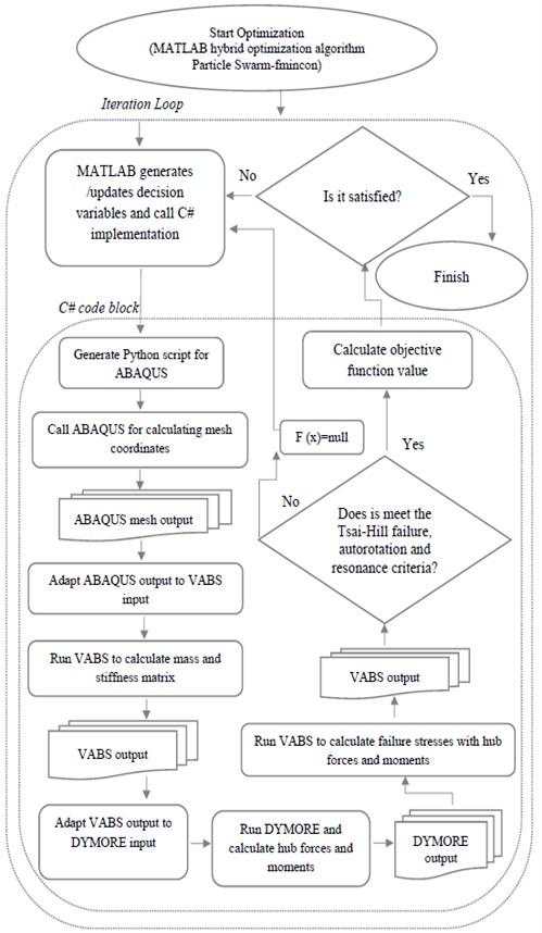
In optimization loop, each iteration must be calculated new fiber angles and new mesh coordinates of the spar geometry to prepare VABS input file. A meshing update is needed because of the geometry parameters changing in each iteration during the optimization process. This is achieved by developing a script code for ABAQUS using Python language. Due to script code without the graphical user interfaces, optimization loop can avoid consuming computer resources by the graphical process. The necessary information generated by VABS is transferred to DYMORE to produce rotor hub forces and moments in given conditions. In order to calculate new objective function value with new hub forces and moments each iteration loop a code implementation is written with C#. This code block integrates ABAQUS, VABS and DYMORE. Each iteration/evaluation MATLAB calls this code implementation, optimization loop is shown in Fig. 6.
Fig. 6Flowchart of optimization loop
In the optimization model, objective function is the surrogate vibration reduction optimization formula. The formula includes combination of the scalar norms of the 4/rev harmonics of longitudinal, lateral, and vertical hub forces (, , ) and pitch, roll, and yaw hub moments (, , ). The aforementioned hub forces and moments are the main source of helicopter vibration owing to transmitting of loadings from the rotor to the fuselage. The objective function can be expressed as:
Decision variables are ply angles in the optimization model. Structural constraints are autorotation, Tsai-Hill failure and natural frequency criterion limitations.
Autorotation constraint supplies that when a technical breakdown occurs in engine or tail-rotor, the freewheeling unit automatically allows the main rotor to rotate freely by disengaging the engine from the main rotor and helicopter can be landed safely. Autorotation constraint is defined as:
where is the mass polar moment of inertia of the rotor when it is spinning about the shaft, and is the baseline value.
Tsai-Hill failure criterion presents interactions of different stress components in failure mechanisms. Experimental observations on isotropic, orthotropic materials and fiber-reinforced materials demonstrate that such interactions can have influence upon the failure of material. At each iteration, all nodes are examined with Tsai-Hill failure criterion to find condition whether allowable or not to continue the iteration. The criterion formula given as:
where , are blade stresses and is shear stress, is shear strength in Tsai-Hill failure criterion. Also, is tensile and compressive strengths respectively in fiber direction, is tensile and compressive strengths respectively in traverse direction.
The physical object under dynamic load vibrates. If this vibration coincides with the natural frequency, resonance occurs and causes a high amplitude vibration response. Natural frequency criterion is defined as:
where is naturel frequency and natural frequency mode. In addition, is Young’s modulus, is moment of inertia, is mass and is blade length.
6. Results and discussion
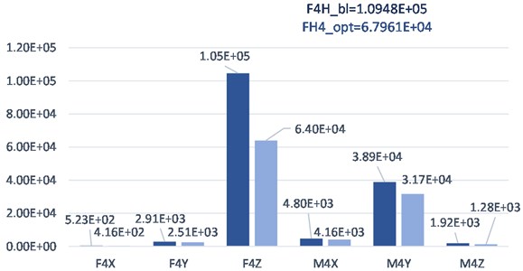
Helicopter rotor blade vibration reduction optimization study achieved approximately 38 % improvement compared with initial value. The graphical comparison of optimum result and baseline value is given in Fig. 7.
Fig. 7Comparison of baseline and optimum solution of UH-60
The Sikorsky UH-60 reference blade was taken from Kumar’s [17] study. Kumar [17] attained 27 % improvement on vibration reduction with CUS ply angles distribution by same objective function and conditions.
The results demonstrate that the vertical hub force is the most reason in the blade vibration among hub forces and moments. The fact that the blades are the main load carriers has a great effect on the vertical hub force causing vibration. The helicopter rotor blades not only carry the weight of the system and expose to the forces occurring on the surface in the vertical axis, but also the force of the helicopter's lift ability is in this direction. The combination of the mentioned forces in vertical directions influences the system strongly and causes flapping vibrations.
The optimization model was run 30 times. Due to the probability and randomness involved in heuristic algorithms, both succeeded and unsuccessful results were also achieved. When examined all running results and comparisons, given in Table 3, the attained topmost 16 optimum results are better than the Kumar’s optimization result. Hub moments and forces of the baseline blade is given in first row which is labeled 0.
Table 3Calculated vibration reduction optimization results and hub forces and moments values
Run number | Stop iteration | Running time (days) | (N) | (N) | (N) | (Nm) | (Nm) | (Nm) | Obj. Func. (N) | Δ % |
0 (Baseline) | - | - | -5.23E+02 | 2.91E+03 | -1.05E+05 | -4.80E+03 | 3.89E+04 | 1.92E+03 | 1.095E+05 | 0.00 |
1 | 143 | 5.0 | -4.16E+02 | 2.51E+03 | -6.40E+04 | -4.16E+03 | 3.17E+04 | 1.28E+03 | 6.796E+04 | 37.92 |
2 | 137 | 4.8 | -4.11E+02 | 2.55E+03 | -6.52E+04 | -4.18E+03 | 3.09E+04 | 1.35E+03 | 6.910E+04 | 36.89 |
3 | 172 | 6.0 | -3.77E+02 | 2.47E+03 | -6.60E+04 | -4.11E+03 | 2.87E+04 | 1.23E+03 | 6.956E+04 | 36.47 |
4 | 156 | 5.4 | -4.34E+02 | 2.91E+03 | -6.56E+04 | -4.82E+03 | 3.31E+04 | 1.32E+03 | 6.979E+04 | 36.25 |
5 | 147 | 5.1 | -3.80E+02 | 2.48E+03 | -6.64E+04 | -4.12E+03 | 2.89E+04 | 1.23E+03 | 7.005E+04 | 36.01 |
6 | 164 | 5.7 | -4.24E+02 | 2.54E+03 | -6.65E+04 | -4.21E+03 | 3.22E+04 | 1.33E+03 | 7.052E+04 | 35.58 |
7 | 132 | 4.6 | -3.64E+02 | 2.08E+03 | -6.84E+04 | -3.53E+03 | 2.79E+04 | 1.38E+03 | 7.189E+04 | 34.34 |
8 | 169 | 5.9 | -3.44E+02 | 1.99E+03 | -6.97E+04 | -3.35E+03 | 2.61E+04 | 1.45E+03 | 7.298E+04 | 33.34 |
9 | 136 | 4.7 | -4.43E+02 | 2.80E+03 | -6.90E+04 | -4.66E+03 | 3.38E+04 | 1.40E+03 | 7.326E+04 | 33.09 |
10 | 142 | 4.9 | -4.66E+02 | 2.97E+03 | -6.99E+04 | -4.96E+03 | 3.57E+04 | 1.42E+03 | 7.442E+04 | 32.03 |
11 | 157 | 5.5 | -3.43E+02 | 1.96E+03 | -7.17E+04 | -3.32E+03 | 2.62E+04 | 1.38E+03 | 7.500E+04 | 31.49 |
12 | 151 | 5.2 | -3.57E+02 | 1.91E+03 | -7.33E+04 | -3.22E+03 | 2.70E+04 | 1.56E+03 | 7.668E+04 | 29.96 |
13 | 134 | 4.7 | -3.75E+02 | 2.58E+03 | -7.44E+04 | -4.32E+03 | 2.88E+04 | 1.15E+03 | 7.800E+04 | 28.76 |
14 | 149 | 5.2 | -3.75E+02 | 2.58E+03 | -7.44E+04 | -4.32E+03 | 2.88E+04 | 1.15E+03 | 7.800E+04 | 28.76 |
15 | 153 | 5.3 | -3.68E+02 | 2.20E+03 | -7.54E+04 | -3.70E+03 | 2.79E+04 | 1.46E+03 | 7.884E+04 | 27.99 |
16 | 148 | 5.1 | -3.36E+02 | 1.91E+03 | -7.59E+04 | -3.23E+03 | 2.55E+04 | 1.44E+03 | 7.907E+04 | 27.78 |
17 | 141 | 4.9 | -3.32E+02 | 1.99E+03 | -7.71E+04 | -3.38E+03 | 2.54E+04 | 1.33E+03 | 8.022E+04 | 26.73 |
18 | 152 | 5.3 | -4.00E+02 | 2.32E+03 | -7.65E+04 | -3.93E+03 | 3.07E+04 | 1.45E+03 | 8.036E+04 | 26.60 |
19 | 132 | 4.6 | -3.52E+02 | 2.01E+03 | -7.80E+04 | -3.41E+03 | 2.68E+04 | 1.41E+03 | 8.130E+04 | 25.74 |
20 | 156 | 5.4 | -3.25E+02 | 1.92E+03 | -7.90E+04 | -3.26E+03 | 2.47E+04 | 1.28E+03 | 8.210E+04 | 25.01 |
21 | 162 | 5.6 | -3.65E+02 | 1.74E+03 | -7.97E+04 | -2.95E+03 | 2.73E+04 | 1.81E+03 | 8.309E+04 | 24.11 |
22 | 155 | 5.4 | -3.32E+02 | 1.71E+03 | -8.26E+04 | -2.89E+03 | 2.48E+04 | 1.57E+03 | 8.564E+04 | 21.78 |
23 | 134 | 4.7 | -3.06E+02 | 1.80E+03 | -8.43E+04 | -3.07E+03 | 2.35E+04 | 9.98E+02 | 8.725E+04 | 20.31 |
24 | 146 | 5.1 | -3.71E+02 | 2.06E+03 | -8.61E+04 | -3.50E+03 | 2.83E+04 | 1.50E+03 | 8.966E+04 | 18.11 |
25 | 164 | 5.7 | -4.06E+02 | 2.34E+03 | -8.71E+04 | -3.97E+03 | 3.12E+04 | 1.45E+03 | 9.098E+04 | 16.90 |
26 | 154 | 5.3 | -3.95E+02 | 2.43E+03 | -8.76E+04 | -4.12E+03 | 3.02E+04 | 1.50E+03 | 9.139E+04 | 16.53 |
27 | 137 | 4.8 | -4.56E+02 | 2.69E+03 | -8.83E+04 | -4.46E+03 | 3.44E+04 | 1.58E+03 | 9.262E+04 | 15.40 |
28 | 135 | 4.7 | -3.86E+02 | 2.26E+03 | -9.37E+04 | -3.83E+03 | 2.94E+04 | 1.52E+03 | 9.733E+04 | 11.10 |
29 | 147 | 5.1 | -4.32E+02 | 2.51E+03 | -9.93E+04 | -4.22E+03 | 3.27E+04 | 1.72E+03 | 1.034E+05 | 5.57 |
30 | 151 | 5.2 | -3.70E+02 | 1.93E+03 | -1.01E+05 | -3.29E+03 | 2.78E+04 | 1.69E+03 | 1.048E+05 | 4.28 |
The optimization runnings did not suggest CUS or CAS ply angle distribution for the decision variables. The suggested free angle distribution for optimization runnings is given in Table 4. In the table, run number with labeled 0 is denoted to the ply angles of baseline blade.
Each optimization running lasted in the range of 4-6 days. Optimization study was run on a PC with Intel Core i7-2670QM processor and 16 GB RAM running the Windows operating system.
A hybrid of PSO and gradient-based techniques was preferred as the optimization method. MATLAB software was used for the hybrid optimization algorithm. Default stopping criterion parameters was used in MATLAB for PSO-fmincon hybrid algorithm, only particle size was taken as 100 for PSO.
Table 4Design variables of optimization results
Run number | ||||||||||||||||
0 (Baseline) | 90.0 | -45.0 | 45.0 | 0.0 | 90.0 | -45.0 | 45.0 | 0.0 | 90.0 | -45.0 | 45.0 | 0.0 | 90.0 | -45.0 | 45.0 | 0.0 |
1 | 79.4 | 53.1 | -5.8 | -24.7 | 48.4 | -51.6 | 52.4 | 46.2 | -61.6 | 44.5 | -44.9 | 10.5 | 75.4 | -40.8 | -85.8 | 29.2 |
2 | -9.9 | -22.8 | 56.4 | 6.4 | 29.5 | -37.9 | 42.3 | 2.5 | 62.1 | 41.1 | -46.8 | -25.6 | 41.2 | -35.8 | -6.8 | 37.4 |
3 | 78.2 | 23.3 | -16.7 | -33.6 | -86.8 | -51.5 | 76.5 | -11.6 | -88.8 | 5.5 | -38.6 | 64.4 | -11.8 | -74.7 | -49.9 | 33.1 |
4 | -13.8 | -21.5 | 52.5 | 21.2 | 30.1 | -25.6 | 27.3 | 22.3 | 30.1 | 18.4 | 21.2 | -21.9 | 51.2 | 37.2 | -40.8 | 34.2 |
5 | 78.2 | 23.3 | -16.7 | -33.6 | -86.8 | -51.5 | 76.5 | -11.6 | -88.8 | 5.5 | -38.6 | 64.4 | -11.8 | -74.7 | -49.9 | 33.1 |
6 | 65.1 | 29.5 | 22.3 | -20.7 | 73.1 | -47.6 | -1.7 | -22.7 | 46.1 | -44.7 | 8.1 | 47.3 | -48.6 | 80.2 | -67.8 | 51.4 |
7 | -38.5 | -43.9 | 41.3 | -0.5 | -41.9 | 52.1 | 58.1 | -60.7 | -9.8 | 11.4 | 74.3 | -52.9 | -9.9 | 43.1 | 50.4 | -78.7 |
8 | 29.2 | -81.6 | -34.8 | 16.2 | -67.8 | -58.8 | -50.9 | 70.3 | 71.2 | 20.2 | -50.6 | 35.1 | -36.7 | 38.2 | -3.7 | 57.2 |
9 | 61.3 | 30.2 | -2.5 | -42.9 | 89.2 | -71.6 | 36.1 | -74.6 | -71.7 | 22.4 | -18.9 | -27.8 | -44.9 | 73.3 | -82.6 | 56.1 |
10 | -83.6 | -1.7 | 20.1 | -24.7 | 38.2 | 58.2 | -28.7 | 42.2 | -42.9 | -23.8 | 28.4 | 38.2 | -82.6 | -84.8 | -56.9 | 78.3 |
11 | -4.9 | 19.1 | -59.7 | 35.1 | -62.5 | 67.2 | -86.7 | 59.4 | -2.6 | -29.6 | 36.3 | -31.9 | 21.5 | 41.3 | 35.5 | 0.2 |
12 | 46.1 | -32.9 | 27.2 | -32.9 | -60.7 | 35.2 | 57.2 | -61.9 | -20.8 | -38.8 | 6.3 | 41.1 | -28.7 | 6.1 | 79.5 | 54.4 |
13 | 72.1 | 32.3 | 8.3 | -37.3 | -87.1 | -66.3 | -23.4 | -25.1 | -27.6 | 13.5 | -87.3 | -24.6 | -28.1 | -84.1 | 57.5 | -67.4 |
14 | 40.4 | 20.3 | -68.7 | 51.3 | 64.1 | 76.4 | -47.9 | -51.6 | -86.6 | -15.9 | -40.7 | -75.5 | 73.5 | -69.8 | -70.9 | 28.5 |
15 | -48.7 | -6.7 | 33.2 | -63.7 | -43.7 | 33.2 | 60.1 | -58.7 | -46.6 | -33.5 | 71.5 | 21.1 | 64.1 | -45.9 | -56.9 | -4.8 |
16 | 85.3 | 21.1 | 47.2 | -56.8 | 81.2 | -64.9 | 50.5 | -75.7 | 67.3 | 87.2 | -23.7 | 23.5 | -85.5 | 23.1 | 68.5 | 42.5 |
17 | 86.2 | 55.2 | 27.3 | -52.6 | 82.4 | 84.4 | -55.6 | -81.8 | -78.9 | -16.6 | -15.8 | -63.9 | 6.5 | 22.1 | 29.2 | -48.7 |
18 | 80.4 | -34.7 | -12.8 | 46.9 | 70.1 | 35.2 | -35.9 | -69.5 | 40.3 | 55.4 | -42.1 | 9.8 | 7.3 | -34.8 | 59.4 | -8.2 |
19 | -3.5 | 18.3 | -58.9 | 34.2 | -61.7 | 69.5 | -85.9 | 59.1 | -3.6 | -30.8 | 36.5 | -30.5 | 23.2 | 41.1 | 36.2 | 2.3 |
20 | -26.7 | -29.8 | 51.4 | -42.6 | 37.2 | 9.5 | -81.8 | 35.4 | -56.9 | -80.9 | -34.6 | 12.4 | -77.8 | -29.6 | -20.9 | -86.6 |
21 | -51.8 | -53.7 | 34.3 | -20.6 | 59.2 | -61.7 | 38.2 | -80.5 | -32.6 | -7.6 | 47.4 | -44.7 | -48.9 | -75.9 | -34.9 | 51.1 |
22 | 60.3 | 89.2 | 24.1 | -55.6 | -77.7 | 70.1 | -59.8 | -9.9 | 24.3 | 44.5 | -19.6 | -33.8 | -87.9 | 72.5 | 32.3 | -63.6 |
23 | 90.0 | 21.8 | -63.1 | 46.8 | 60.0 | 90.0 | -31.2 | -90.0 | -90.0 | -32.2 | -22.7 | -34.5 | -90.0 | 90.0 | 54.0 | 30.5 |
24 | -27.9 | 48.1 | -24.4 | -8.6 | -73.3 | 86.2 | 39.4 | 9.9 | 48.9 | 32.7 | -30.8 | -50.2 | 73.5 | -78.9 | 47.7 | -34.4 |
25 | -65.8 | 4.2 | -51.6 | 45.2 | 28.2 | 87.4 | -41.8 | 63.1 | -52.8 | 16.2 | 69.4 | -23.8 | -82.9 | 69.1 | 31.4 | 44.1 |
26 | -60.8 | -4.8 | 11.2 | 17.1 | 85.1 | -78.6 | -49.5 | -80.9 | 83.1 | 61.2 | 54.5 | -58.9 | -38.5 | 52.4 | -55.6 | -13.7 |
27 | -11.3 | 0.9 | -34.3 | 29.2 | -49.7 | 34.3 | -40.7 | 61.5 | -73.4 | 13.8 | 38.3 | 46.5 | -25.1 | -42.5 | 31.9 | -37.6 |
28 | -73.7 | -21.8 | -41.2 | 75.2 | -33.4 | 47.8 | -56.6 | 14.8 | -23.3 | -35.4 | 25.6 | -14.6 | -54.1 | -30.6 | -90.4 | 59.2 |
29 | -13.1 | -0.5 | 54.1 | -54.0 | 30.2 | -67.4 | 71.8 | -67.0 | -33.3 | 27.4 | 0.2 | -41.7 | -26.3 | 26.2 | -72.7 | -75.0 |
30 | -40.7 | -23.6 | 46.4 | -37.6 | 31.1 | 20.4 | -81.9 | 48.4 | -53.9 | -78.7 | -28.6 | 24.3 | -76.8 | -23.7 | -32.9 | -86.9 |
( ply angles) | ||||||||||||||||
7. Conclusions
In the optimization process many software’s has used for different aims. VABS is a linear two-dimensional cross-sectional analysis software which is based on general finite elements and VAM. VABS calculates mass and stiffness matrix for using as an input parameter to DYMORE nonlinear one-dimensional beam analysis. ABAQUS was created meshes to enter cross-section geometry into the VABS. PYHTON script was used to perform parametric study in ABAQUS. VABS calculated the stress parameters to be used in the Tsai-Hill failure criterion with the forces and moments produced by DYMORE.
Conversion of input and output formats of all these programs to each other and the sequential execution and shutdown processes were done with the codes written in the C#. As seen Fig. 6, MATLAB triggered all the written codes and software’s to reach optimum value of objective function for each iteration.
When examining approximately 38 % improvement of optimization study, the developed integrated algorithm and the written codes, selected optimization algorithm and the free angle orientation proposal should be considered as a whole. The chosen hybrid algorithm produced succeeding results due to the ability of gradient-based algorithms find the best result in a given area and the advantage of the large searching space of heuristic methods.
Also results demonstrate that it is possible to achieve better strength and structural rigidity with free angles distribution. Despite the advantages of easier manufacturing of CUS and CAS angle distributions, it is concluded that better performance is obtained from free angle distributions.
In future studies about helicopter rotor blade vibration reduction, different calculations can be made with different optimization methods and angle orientation suggestions. In addition, the results of these studies can be dealt with sensitivity analysis, and thus inputs as the ply angle distributions, variables, constraints, parameters and software’s that the most affected the system can be examined.
References
-
P. P. Friedmann and T. A. Millott, “Vibration reduction in rotorcraft using active control – a comparison of various approaches,” Journal of Guidance, Control, and Dynamics, Vol. 18, No. 4, pp. 664–673, 1995, https://doi.org/10.2514/3.21445
-
A. Kovalovs, E. Barkanov, S. Ruchevskis, and M. Wesolowski, “Optimisation methodology of a full-scale active twist rotor blade,” Procedia Engineering, Vol. 178, pp. 85–95, 2017, https://doi.org/10.1016/j.proeng.2017.01.067
-
D. Meng, P. Xia, K. Lang, E. C. Smith, and C. D. Rahn, “Neural network based hysteresis compensation of piezoelectric stack actuator driven active control of helicopter vibration,” Sensors and Actuators A: Physical, Vol. 302, p. 111809, Feb. 2020, https://doi.org/10.1016/j.sna.2019.111809
-
J.-S. Park and J.-H. Kim, “Design and aeroelastic analysis of active twist rotor blades incorporating single crystal macro fiber composite actuators,” Composites Part B: Engineering, Vol. 39, No. 6, pp. 1011–1025, Sep. 2008, https://doi.org/10.1016/j.compositesb.2007.11.006
-
M. Sayed, A. A. Mousa, and I. Mustafa, “Stability and bifurcation analysis of a buckled beam via active control,” Applied Mathematical Modelling, Vol. 82, pp. 649–665, Jun. 2020, https://doi.org/10.1016/j.apm.2020.01.074
-
M. Sayed and A. A. Mousa, “Vibration, stability, and resonance of angle-ply composite laminated rectangular thin plate under multiexcitations,” Mathematical Problems in Engineering, Vol. 2013, pp. 1–26, 2013, https://doi.org/10.1155/2013/418374
-
F. Gandhi and M. K. Sekula, “Helicopter vibration reduction using fixed-system auxiliary moments,” AIAA Journal, Vol. 42, No. 3, pp. 501–512, Mar. 2004, https://doi.org/10.2514/1.575
-
P. Friedmann, C. Venkatesan, and K. Yuan, “Development of a structural optimization capability for the aeroelastic tailoring of composite rotor blades with straight and swept tips,” in 4th Symposium on Multidisciplinary Analysis and Optimization, pp. 722–748, Sep. 1992, https://doi.org/10.2514/6.1992-4779
-
J. W. Lim and I. Chopra, “Aeroelastic optimization of a helicopter rotor using an efficient sensitivity analysis,” Journal of Aircraft, Vol. 28, No. 1, pp. 29–37, Jan. 1991, https://doi.org/10.2514/3.45989
-
R. Ganguli and I. Chopra, “Aeroelastic optimization of a helicopter rotor to reduce vibration and dynamic stresses,” Journal of Aircraft, Vol. 33, No. 4, pp. 808–815, Jul. 1996, https://doi.org/10.2514/3.47018
-
R. Ganguli, “Optimum design of a helicopter rotor for low vibration using aeroelastic analysis and response surface methods,” Journal of Sound and Vibration, Vol. 258, No. 2, pp. 327–344, Nov. 2002, https://doi.org/10.1006/jsvi.2002.5179
-
B. Glaz, P. P. Friedmann, and L. Liu, “Surrogate based optimization of helicopter rotor blades for vibration reduction in forward flight,” Structural and Multidisciplinary Optimization, Vol. 35, No. 4, pp. 341–363, Apr. 2008, https://doi.org/10.1007/s00158-007-0137-z
-
B. Glaz, T. Goel, L. Liu, P. P. Friedmann, and R. T. Haftka, “Multiple-surrogate approach to helicopter rotor blade vibration reduction,” AIAA Journal, Vol. 47, No. 1, pp. 271–282, Jan. 2009, https://doi.org/10.2514/1.40291
-
G. Narayana Naik, S. Gopalakrishnan, and R. Ganguli, “Design optimization of composites using genetic algorithms and failure mechanism based failure criterion,” Composite Structures, Vol. 83, No. 4, pp. 354–367, Jun. 2008, https://doi.org/10.1016/j.compstruct.2007.05.005
-
R. Satheesh, G. Narayana Naik, and R. Ganguli, “Conservative design optimization of laminated composite structures using genetic algorithms and multiple failure criteria,” Journal of Composite Materials, Vol. 44, No. 3, pp. 369–387, Feb. 2010, https://doi.org/10.1177/0021998309347579
-
P. Friedmann, “Impact of structural optimization with aeroelastic/multidisciplinary constraints on helicopter rotor design,” in Aerospace Design Conference, pp. 1–22, Feb. 1992, https://doi.org/10.2514/6.1992-1001
-
D. Kumar, “Design and Analysis of Composite Rotor Blades for Active/Passive Vibration Reduction,” Ph.D. Dissertation, University of Michigan Department of Aerospace Engineering, 2013.
-
V. L. Berdichevskii, “Variational-asymptotic method of constructing a theory of shells,” Journal of Applied Mathematics and Mechanics, Vol. 43, No. 4, pp. 711–736, Jan. 1979, https://doi.org/10.1016/0021-8928(79)90157-6
-
D. H. Hodges and W. Yu, “A rigorous, engineer-friendly approach for modelling realistic, composite rotor blades,” Wind Energy, Vol. 10, No. 2, pp. 179–193, Mar. 2007, https://doi.org/10.1002/we.215
-
Wenbin Yu, “VABS Manual for Users,” Utah State University, Logan, USA, Jan. 2011.
-
P. Roth-Johnson, R. E. Wirz, and E. Lin, “Structural design of spars for 100-m biplane wind turbine blades,” Renewable Energy, Vol. 71, pp. 133–155, Nov. 2014, https://doi.org/10.1016/j.renene.2014.05.030
-
M. Rafiee, F. Nitzsche, and M. Labrosse, “Dynamics, vibration and control of rotating composite beams and blades: A critical review,” Thin-Walled Structures, Vol. 119, pp. 795–819, Oct. 2017, https://doi.org/10.1016/j.tws.2017.06.018
-
Olivier A. Bauchau, “DYMORE User’s Manual,” Georgia Institute of Technology, Atlanta, USA, Jan. 2010.
-
V. Berdichevsky, E. Armanios, and A. Badir, “Theory of anisotropic thin-walled closed-cross-section beams,” Composites Engineering, Vol. 2, No. 5-7, pp. 411–432, Jan. 1992, https://doi.org/10.1016/0961-9526(92)90035-5
-
Z. Qin and L. Librescu, “On a shear-deformable theory of anisotropic thin-walled beams: further contribution and validations,” Composite Structures, Vol. 56, No. 4, pp. 345–358, Jun. 2002, https://doi.org/10.1016/s0263-8223(02)00019-3
-
H.-J. Chun, M.-J. Park, and J.-H. Byun, “Behaviors of CAS and CUS thick-walled channel composite beams,” International Journal of Modern Physics B, Vol. 20, No. 25n27, pp. 4016–4021, Oct. 2006, https://doi.org/10.1142/s0217979206040787
-
G. E. Beshay, K. Y. Maalawi, S. M. Abdrabbo, and T. A. Khalifa, “Dynamic optimization of thin-walled composite blades of wind turbines,” World Applied Sciences Journal, Vol. 33, No. 3, pp. 525–535, Jan. 2015.
-
J. Warminski, J. Latalski, and Z. Szmit, “Coupled flexural-torsional vibrations of a composite beam attached to a rotating hub,” in 9th International Conference on Structural Dynamics, EURODYN 2014, pp. 1883–1889, Jun. 2014.
Cited by
About this article

