Abstract
The dynamic vibration absorber, which is adopted to suppress the unbalanced vibration of rotor, is optimized for the optimal parameters in this paper. This paper proposes a parameter optimization method for dynamic vibration absorbers and seeks parameters of a dynamic vibration absorber with better vibration suppression performance. Firstly, the frequency response function of the dynamic vibration absorber-rotor coupling system is obtained by using the finite element method. Then, basing on the optimal mathematical model, the optimal design variables are solved with the adaptive particle swarm optimization algorithm. Also, an example is used to prove the validity of the optimization design method mentioned in this paper. Further, in order to master the influence of deviation from the optimal value on the suppressing vibration effect, the vibration suppression performance changes of the dynamic vibration absorber whose parameters deviate from the optimal value are analyzed. The results show that: compared with conventional design method, this method is more superior; The dynamic vibration absorber with optimal parameters has better vibration suppression performance; At the same degree deviated from the optimal value, the stiffness has a more remarkable influence on the vibration suppression performance than damping for suppressing the first resonance; For the dynamic vibration absorber which is adopted to suppress the fixed-frequency vibration, the influence of stiffness deviation on the vibration suppression performance appears an obvious interval which is related to working speed.
1. Introduction
In modern rotating machinery, most of them work at supercritical or higher speed. Various factors, such as uneven adhesion of dirt, wear or shedding of impeller and blades, might lead to mass unbalances of the system during long-term operation. The mass unbalances will cause vibration of the systems increase. If this problem gets worse, the equipment running stability and safety will be seriously affected.
The usual measure to solve unbalance fault is to return factories for making the dynamic balance [1-3], which not only requiring expensive maintenance, but also caused great economic losses due to production shutdown. In order to solve the problem of downtime maintenance, the automatic balancing technology, which includes passive and active automatic balancing, is developed. In passive automatic balancing technology, spherical structure [4] and pendulum structure [5] are appended in the rotor structure to suppress vibration of the rotor. There are various forms of active automatic balancing mechanism. Early online automatic balancing technology is to online re-balance the systems with unbalanced failure, the main methods of which are as follows: (a) On the correction planes, to increase weight online by spraying [6], or to reduce weight online by using electro corrosion and laser cutting [7], is effective for small-sized rotors, but it has many shortcomings, such as a bad effect on large scale rotor, stress concentration and so on. (b) To redistribute mass, the mass blocks are drove online [8], which requires a greater quality counterweight structure and sustained provision of energy. Late online automatic balancing technology, which mainly takes the form of applying recreation forces on the rotor structure, often uses the following methods: (a) For balancing the system, to apply real-time recreation forces to the rotor system by using controllable electromagnetic bearings [9-11]. (b) To apply a real-time variable damping force to the system by using controlled magnetorheological fluid damper [12-15]. However, the precipitation problem of magnetorheological fluids affects long-term use. On-line balancing structures require additional control devices and consume a great deal of energy.
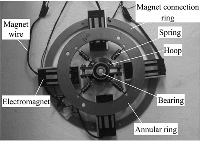
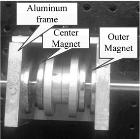
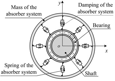
In order to find a convenient and economical way to suppress vibration, some scholars have applied the dynamic vibration absorber to the rotor vibration suppression field. Zhang et al. [16] reduced the first order resonance amplitude by 70 % adopting the passive ring dynamic vibration absorbers; Hu et al. [17] effectively reduced the violent vibration when the rotor starts to pass the first critical speed by adopting the rotor dynamic vibration absorber; Yao et al. [18] effectively reduced the lateral vibration of the rotor system by adopting the vibration absorber with negative stiffness property. It is not given definite parameter optimization methods of the dynamic vibration absorbers mentioned in the above references, which means that they do not have optimal vibration suppression performance. In addition, as for the structure, damping elements is not fully considered in the dynamic vibration absorbers mentioned in the above references, which are shown in Fig. 1.
Based on the above problems, in this paper, the dynamic vibration absorber, which is adopted to suppress the first resonance and fixed-frequency vibration, was optimized for the optimal parameters, and the vibration suppression performance of the absorber was studied when the parameter deviates from the optimal value. Dynamic vibration absorbers have mass, spring and damping unit. For solving the optimal parameters of the dynamic vibration absorbers, this paper presents an optimization methods based on the finite element theory and the adaptive particle swarm optimization algorithm. Firstly, the frequency response function of the dynamic vibration absorber-rotor coupling system is obtained by using the finite element method. Then, by taking stiffness and damping as the design variables, the optimal mathematical model is established based on the frequency response function. And the optimization problem is solved with the adaptive particle swarm optimization algorithm. In order to prove the effectiveness of the optimization method, the optimal parameters are compared with the optimal parameters solved by the common optimization methods. The influence of parameters deviation from the optimal value on vibration suppression performance is analyzed to further master the effect of parameter variation on the absorbers.
Fig. 1For the translation mechanism and the rotating body of the dynamic vibration absorber
a)
b)
2. Kinetic equation of the dynamic vibration absorber-rotor coupling system and programming for optimization problems
2.1. Kinetic equation of the dynamic vibration absorber-rotor coupling system
(1) Kinetic equation of the rotor system without dynamic vibration absorber.
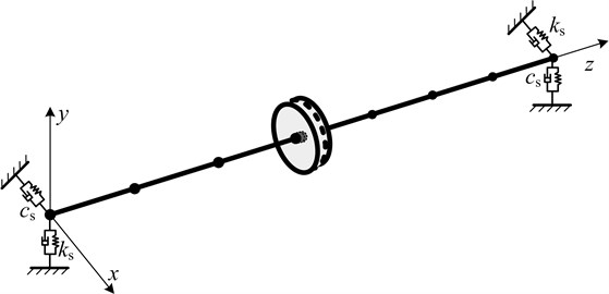
The rotor system is a single span-single disk structure which is shown in Fig. 2. Linear symmetric supports are adopted at the both ends of the rotation axle. There is mass eccentricity for disk.
Fig. 2System diagram
The rotor system without dynamic vibration absorber is dispersed into nodes and flexible shaft section elements by finite element method. The shaft section element, as showed in Fig. 3, takes the Euler Bernoulli beam model.
Fig. 3Euler Bernoulli beam model
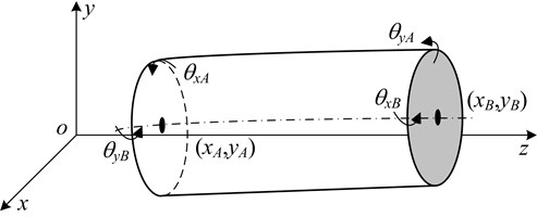
Generalized coordinate of each shaft section element is as follows:
Considering the gyroscopic moment and moment of inertia, the kinetic equation of the rotor system can be formulated as follows based on the Lagrange equation:
(2) Dynamic model simplification of rotor dynamic vibration absorber.
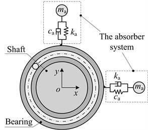
Based on the structure of vibration absorbers reported in the references, the structure of the vibration absorber designed in this paper is shown in Fig. 4(a). Because the rotor system is mainly affected by unbalanced forces, the rotor dynamic vibration absorber is decomposed into two independent, single degree of freedom, mass - damping - spring systems, are shown in the dotted boxes in Fig. 4.
(3) Dynamic modeling of dynamic vibration absorber-rotor coupling system.
Introducing the simplified vibration absorber in the rotor system, the kinetic equation of the dynamic vibration absorber -rotor coupling system can be expressed as:
where:
Fig. 4Model simplification of rotor dynamic vibration absorber
a)
b)
Let , , then Eq. (3) can be transferred as:
Then, the response amplitude of the system can be expressed as:
where:
The frequency response function of the th node in the system can be expressed as:
where, let denote the th row of .
In what follows, we refer to the rotor system without dynamic vibration absorber as the original system, the system composed of dynamic vibration absorber and rotor system as coupling system, the rotor system in coupling system as the main system.
2.2. Programming for optimization problems
(1) Optimization mathematical model.
There are two types of dynamic vibration absorber, which are used to suppress vibration of the rotor system affected by unbalanced forces: One is used to suppress the first resonance of the rotor system during startup process, to reduce the response amplitude of first resonances; and another used to suppress the fixed-frequency vibration generated while the rotor running at speed to reduce vibration response amplitude. But one thing they have in common is that the optimization design methods they used, which can obtain the minimum response amplitude of the main system by finding optimal stiffness and damping of absorber. Based on this aspect, the design variable and objective function of optimization design is the same for both types, that is:
– The objective function is .
– The design variable is .
The aim to attach the dynamic vibration absorber for suppressing the first resonance is not to minimize the amplitude of the main system while it running at speed , but to minimize the first resonance amplitude during its startup process. But aim to attach the dynamic vibration absorber for suppressing the fixed-frequency vibration is to minimize response amplitude of the main system while it running at speed . So, for the optimization design of two types of dynamic vibration absorber, there are some differences in the extremal problem of the objective function and constraint condition, which are as follows:
a) The dynamic vibration absorber for suppressing the first resonance of the rotor system:
The objective function is ;
The constraint condition is 0 , 0 , .
b) The dynamic vibration absorber for suppressing the fixed-frequency vibration:
The objective function is ;
The constraint condition is 0 , 0 , .
By means of the parameters substitution, the optimization design of two types of dynamic vibration absorber can be described as follows:
The dynamic vibration absorber for suppressing the first resonance of the rotor system
In the range of 0 2, 0 1 and 0.8 1.2, to find the best design variable that satisfies the function of:
where, the frequency ratio of the dynamic vibration absorber is . The damp ratio of the dynamic vibration absorber is , .
a) The dynamic vibration absorber for suppressing the fixed-frequency vibration
In the range of 0 2, 0 1, and 1, to find the best design variable that satisfies the function of:
where, the frequency ratio of the dynamic vibration absorber is . The damp ratio of the dynamic vibration absorber is , .
(2) Optimization method.
Because the discrete system has a large number of degrees of freedom, it is difficult to find a definite optimal solution formula, although the frequency response function of the coupling system can obtain the semi-numerically semi-analytical response solution. In this case, can only adopt a numerical optimization method to find optimal design variable that satisfies the Eq. (7) or Eq. (8). The adaptive particle swarm optimization algorithm method is adopted to solve the optimization mathematical model in this paper, as showed in the following steps.
(a) Single degree of freedom system, which can be equivalent to the original system, is solved by the characteristic vector method [19]. And then the absorber which is applicable to this system is designed in this step, the parameter of which is ; (b) By using an adaptive particle swarm optimization algorithm method, the optimal value of is searched. Initialize each particle of the initial particle group randomly in the region that ; The fitness functions for optimizing the two dynamic vibration absorbers is respectively defined as and .
For details of adaptive particle swarm optimization algorithm method, refer to [20] listed in references.
3. Numerical simulations
3.1. Parameters and modal analysis of the original system
The original system is dispersed into 10 nodes. And the specific parameters of each shaft section are shown in Table 1. The node is in the center of the disc, mass eccentricity moment of which is 1×10⁻⁵ kgm. Both node and are in a support position, their support stiffness is 1×10⁸ N/m, their damping is 7×10⁵ Ns/m.
Table 1Parameters of shaft
Parameters | / mm | / mm | Parameters | / mm | / mm |
60 | 10 | 50 | 10 | ||
60 | 10 | 50 | 10 | ||
50 | 10 | 50 | 10 | ||
10 | 80 | 50 | 10 | ||
10 | 80 | – | – | – |
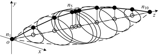
Performing modal analysis on the original system, the results are shown in Table 2 and Fig. 5 respectively, to obtain the first two critical speeds and the first vibration mode.
Observing the vibration shape diagram shows that the maximum amplitude node of the original system is , when the first resonance occurs. So, we act as an objective vibration suppression point, and its amplitude as an evaluation object for vibration suppression performance of dynamic vibration absorbers.
Table 2Main second order critical speed of the original system
Order | The first order | The second order |
Critical speed / Hz | 52.7 | 389.5 |
Fig. 5First order form of original system
3.2. APSO convergence and accuracy of the algorithm
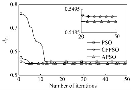
The APSO algorithm is used to optimize the parameters of the dynamic vibration absorber with mass ratio of 0.15, and compared with PSO and CFPSO algorithm. The basic parameters of the APSO algorithm are: the particle dimension is 2, which is the frequency ratio and damping ratio of the absorber; the population size is 100; the number of iterations is 50; the learning factor 2.05, 2.05; the coefficient of variation 1.5 and 2.
After several experiments, the optimal convergence curve in the optimal case is shown in Fig. 6. As can be seen from the figure, the APSO algorithm has a faster convergence rate than the PSO [21] algorithm and the CFPSO [22] algorithm. Also, is smaller than the other two algorithms. This also proves that the APSO algorithm is reliable.
Fig. 6Optimized convergence curves for PSO, CFPSO and APSO Algorithms
3.3. Optimization design of the dynamic vibration for suppressing the first resonance
(1) Comparison with conventional optimal design method.
With suppressing a certain order resonance of the continuum system, often, we calculate the equivalent mass and equivalent stiffness of this order mode, and then simplify this system as a single degree of freedom system. And then attach the single degree of freedom dynamic vibration absorber whose natural frequency is equal or close to the natural frequency of the main system on it. According to whether damping is existed in the main system and the vibration absorber system, two degrees of freedom coupling system are classified into three categories; each one corresponds to a common parameter optimization method. In this section, the three methods are respectively used in the optimization design of dynamic vibration absorber parameters.
The parameters of the single degree of freedom system which is equivalent to the first order mode of the original system are obtained by the characteristic vector method, that is, 1.1073kg, 1.115×10⁵ N/m and 25.3 Ns/m. Here, the mass ratio of the dynamic vibration absorber to the main system is expressed as . Under the condition that 0.15, the dynamic vibration absorber, which is attached at position of node , is optimized.
Approach 1: It is assumed that the main system is a single degree of freedom mass-spring system. Then the dynamic vibration absorber which given the code name DVA1 is designed as a single degree of freedom mass-spring system. In this case, it only needs to meet .
Approach 2: It is assumed that the main system is a single degree of freedom mass-spring system. Then the dynamic vibration absorber which given the code name DVA2 is designed as a single degree of freedom mass-damping-spring system. Research by Den Hartog [23] and Brock [24] shows that the optimal vibration suppression performance can be achieved when the parameters of this type of dynamic vibration absorber satisfies Eq. (9):
Approach 3: It is assumed that the main system is a single degree of freedom mass-damping-spring system. Then the dynamic vibration absorber which given the code name DVA3 is designed as a single degree of freedom mass-damping-spring system. Based on the optimum design formula induced by Seto et al. [25], the optimal vibration suppression performance can be achieved when the parameters of this type of dynamic vibration absorber satisfies Eq. (10):
Based on the above three approaches, single degree of freedom dynamic vibration absorber is designed, and the optimum parameters of which are shown in Table 3.
Table 3Parameters of four types of optimal dynamic vibration absorbers
Types | DVA1 | DVA2 | DVA3 | DVA4 | |
System schematic | 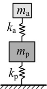 | 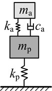 | 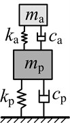 | 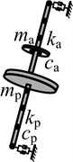 | |
0.9993 | 0.868 | 0.8645 | 0.9911 | ||
0 | 0.2216 | 0.2576 | 0.2976 | ||
/ (N/m) | 1.67×10⁴ | 1.26×10⁴ | 1.25×10⁴ | 1.643×10⁴ | |
/ (N·s/m) | 0 | 19.43 | 22.5 | 29.8 | |
Three different amplitude -frequency curves of the main system which is respectively attached DVA1, DVA2 and DVA3 are shown in Fig. 7. The definition of amplitude magnification , given by the ratio of resonance amplitude of the main system which is attached dynamic vibration absorber and original system, is used to represent the amplitude of the main system. For the main system which is attached DVA1, there are two new formants, which appear in the first order critical speed region of the original system.
Fig. 7Amplitude frequency response of the main system with three types of absorbers
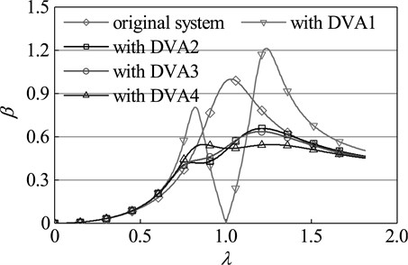
Although the first peak is smaller than the resonance peak of the original system, the second peak far greater than the original peak. So, its vibration suppression effect of suppressing vibration is far from ideal. For the main system which is respectively attached DVA2 and DVA3, the two new resonance peaks of both are smaller than the resonance peak of the original system, and the second peak is far greater than the first. Based on the experience, one can conclude that none of the three types of dynamic vibration absorbers is optimal. Dynamic vibration absorber, which is given the code name DVA4, is designed by means of the method mentioned in this study. For the main system which is attached DVA4, the two new resonance peaks are far smaller than the resonance peak of the original system, and the two are equal. This indicates that DVA4 is the best dynamic vibration absorber and reflects the accuracy and superiority of the parameter optimization method in this paper.
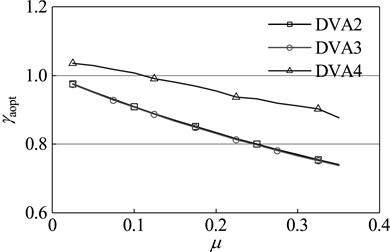
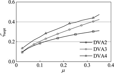
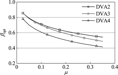
Dynamic vibration absorbers with different mass ratio are optimized by the design methods of DVA2, DVA3 and the optimization method in this paper respectively. The results are shown in Figure 8. As seen in the diagram, with any given mass ratio, compared with other two optimization methods, the dynamic vibration absorber designed by the optimization method in this paper has a higher frequency ratio and damping ratio. From the optimum amplitude magnification perspective, for any given mass ratio, the amplitude magnification of the main system which is attached DVA4 is smaller than that of the main system which is respectively attached DVA2 and DVA3. This fact shows that the dynamic vibration absorber designed by the method of this paper has a better vibration suppression performance, which further proves the effectiveness and superiority of this method.
Fig. 8Optimal parameters of dynamic absorber with different mass ratios of primary system: a) optimal frequency ratio, b) optimal damping ratio, c) amplitude magnification
a)
b)
c)
(2) Vibration suppression performance analysis for dynamic vibration absorber when its parameters deviate from the optimal value.
When the stiffness or the damping deviates from the optimal value (optimal deviation is that the stiffness or the damping is times of optimal value), vibration suppression performance of dynamic vibration absorber will be, undoubtedly, reduced. The performance changes as illustrated in Fig. 9. The mass ratio vary between 0.01-0.35. The deviation interval from the optimal stiffness, or damping, vary between 0.001-4 times of optimal value. The meaning of the vertical coordinate in the diagram is (or ): () = (maximum amplitude of the main system when the stiffness (damping) occurs optimal deviation – optimal amplitude)/(resonance amplitude of the original system – optimal amplitude). The greater the value is, the greater performance degradation will occur. If this value is greater than 1, it is indicated that, the dynamic vibration absorber aggravates the vibration instead of suppressing. When the stiffness deviates from the optimal value, the dynamic vibration absorber with any mass ratio can suppress vibration; At the same deviation degree, performance degradation is more severe for the dynamic vibration absorber with the small mass ratio than large mass ratio.
Fig. 9Impact of the deviation from the optimal parameter on vibration suppression performance: a) when the stiffness deviate from the optimal value, b) when the damping deviate from the optimal value, c) when the stiffness and damping deviate from the optimal value in the same proportion, the sensitivity contrast of vibration suppression performance to the both
a)
b)
c)
When the damping deviates from the optimal value, not all dynamic vibration absorber can suppress vibration. For the dynamic vibration absorber with any mass ratio, the vibration will become stronger when the damping value is below , which are shown in the dark area of Fig. 9; At the same deviation degree, the dynamic vibration absorber with different mass ratio possesses essentially the same degree of vibration suppression performance degradation.
The meaning of Fig. 9(c) is: When the stiffness and damping deviate from the optimal value in the same proportion, for the dynamic vibration absorber with any mass ratio, the sensitivity of its vibration suppression performance to the both deviations. In both colors, the deep color means that the amplitude of the main system when the damping deviates from the optimal value is greater than that when the stiffness deviate from the optimal value; the opposite is the case for light color. With any given mass ratio, the sensitivity of the vibration suppression performance to deviation from optimal stiffness is higher than that to deviation from optimal damping; when the stiffness (damping) is less than optimal value, with the increase of mass ratio, the vibration suppression performance of dynamic vibration absorber become more sensitive to changes of damping.
3.4. Optimum design of dynamic vibration absorber for suppressing the fixed-frequency vibration
Assuming that the amplitude closed to the dangerous threshold of parking while the system running at a fixed speed, in which situation the dynamic vibration absorber needs to be used to suppress vibration and reduce amplitude. This section discusses the parameters optimization design of dynamic vibration absorber for suppressing the fixed-frequency vibration, and changes of vibration suppression performance when its parameters deviate from the optimal value.
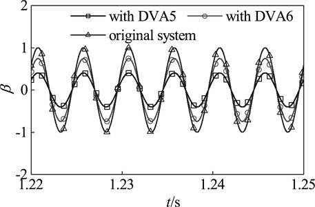
Here, select a speed between the first and second critical speed of the original system, 200 Hz, as the working speed. Select 0.15 as the mass ratio of dynamic vibration absorber. The parameters of optimal dynamic vibration absorber DVA5 are obtained by the optimization method in this paper, which are as follows: 1.0152, 0, that is, 2.665×10⁵ N/m, 0 Nm/s. The time domain response of the coupling system which is attached DVA5 is shown in Fig.10. When DV5 is attached, the amplitude of the main system falls to 40 % of the original system. Compared with the main system which is attached DVA6 whose parameters are and 0, the amplitude of the main system which is attached DVA5 fall by about 45 %. These reflect the effectiveness and superiority of this method in suppressing fixed-frequency vibration.
Fig. 10Time domain response of the main system with DVA5 and DVA6
(1) Parameter optimization for dynamic vibration absorber with different mass ratio.
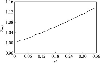
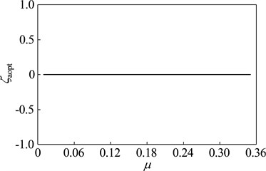
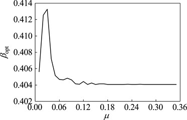
When the vibration frequency meets 200 Hz, the optimization design is studied with dynamic vibration absorber whose mass ratio vary between 0.01-0.35. The parameters and vibration suppression performance of optimal dynamic vibration absorber is shown in Fig. 11. The optimal frequency ratio increases gradually with the rising of the mass ratio; The optimal damping ratios are zero, which indicates that the dynamic vibration absorber without damping elements has better the fixed-frequency vibration suppression performance than that with. With exceptions that the mass ratio is 0.02 and 0.03, the amplitude magnification decreases with the increase of mass ratio.
(2) Relation between the optimal parameters of dynamic vibration absorber and rotational speed.
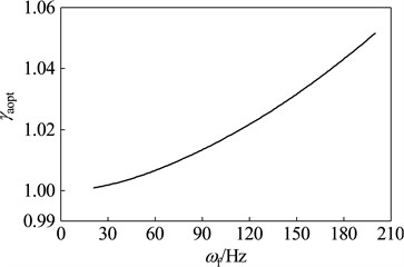
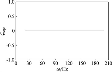
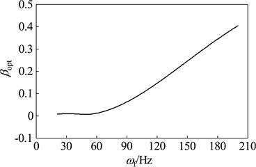
When the rotor run at different working speeds, the parameters and vibration suppression performance of the optimal dynamic vibration absorber is shown in Fig. 12. Here, select 0.15 as the mass ratio of dynamic vibration absorber. As shown in the chart, the optimal frequency ratio is increased gradually with the rising of working speed; the optimal damping ratios under any speeds are zero; the amplitude magnification increases gradually with increasing speed, which indicate that optimal vibration suppression performance reduce gradually with increasing speed.
At different speeds, the ratio of the amplitude magnification of the main system which is attached optimal dynamic vibration absorber and the amplitude magnification of the main system which is attached DAV6 is shown in Fig. 13. It shows the relationship in vibration suppression performance between the two kinds of absorbers. A smaller value of means that the optimal dynamic vibration absorber possesses the higher vibration suppression performance than DVA6. As seen in the diagram, vibration suppression performances of optimal vibration absorber and DVA6 are not constant proportionality under any speed, the vibration suppression performance of the optimal dynamic vibration absorber gradually approaches DVA6 as the speed increases. However, under the speed reaches 200 Hz, one can also find out that the amplitude magnification of the optimal dynamic vibration absorber is only 55 % of that of DVA6, which indicate that the amplitude of the main system which is attached the optimal dynamic vibration absorber is only 55 % of that of the main system which is attached DVA6. Therefore, when designed the dynamic vibration absorber for suppressing the fixed-frequency vibration, the parameters can’t be simply set to .
Fig. 11Optimal parameters of the optimal absorber with different mass ratios while the main system running at ω= 200 Hz: a) optimal frequency ratio, b) optimal damping ratio, c) optimal amplitude magnification
a)
b)
c)
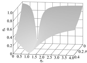
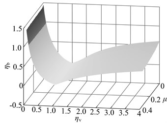
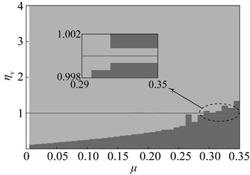
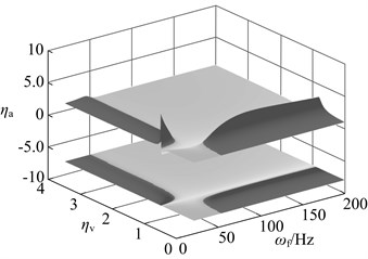
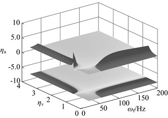
(3) Changes of vibration suppression performance when the stiffness deviates from the optimal value.
The dynamic vibration absorber with mass ratio of 0.05, 0.15 and 0.3 is chosen, and their vibration suppression performance is analyzed when the stiffness deviates from the optimal value. The result is shown in Fig. 14. The meaning of axes in this diagram is: (amplitude of the main system when the stiffness (damping) deviates from the optimal value optimal amplitude) / (the amplitude of the original system optimal amplitude). The bigger value of means that the bigger performance degradation. The dynamic vibration absorber worsens vibration of main system if 1.
In this diagram, at upper there is three dimensional graph whose projection on plane is below the diagram. The deeper the color, the bigger the value of , namely the bigger the performance degradation. The area close to black is used to represent the range of parameters that aggravate vibration. When the stiffness deviates from the optimal value, vibration absorbers with three kinds of mass ratio has the vibration suppression performance in most parameters range. Parameters that aggravate vibration show an obvious interval, such as: When , , the dynamic vibration absorber aggravate vibration of the main system; When , , the dynamic vibration absorber aggravate vibration. This regularity will provide reference for parameters selection of semi-active and active dynamic vibration absorber.
Fig. 12Parameters of the optimal absorber with the mass ratio that μ= 0.15 while the main system running at different speeds: a) optimal frequency ratio, b) optimal damping ratio, c) optimal amplitude magnification
a)
b)
c)
Fig. 13Comparison of the vibration suppression performance of the optimal absorber and DVA6 while the main system running at different speeds
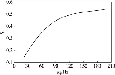
Fig. 14Changes in vibration suppression performance of the dynamic vibration absorber when the stiffness deviate from the optimal value: a) μ= 0.05, b) μ= 0.15, c) μ= 0.3
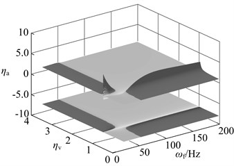
a)
b)
c)
4. Conclusions
In this study, the frequency response function of the dynamic vibration absorber-rotor coupling system is obtained by using the finite element method. Then, basing on the optimal mathematical model, the optimal parameters of the dynamic vibration absorber are successfully solved with the adaptive particle swarm optimization algorithm. By comparing the optimal dynamic absorber with the absorber designed by the common optimization design methods, the validity and superiority of the optimization method are verified.
For the dynamic absorber which is adopted to suppress the first resonance, the stiffness has a greater influence on the vibration suppression performance than damping in most cases. For the dynamic vibration absorber which is adopted to suppress the fixed-frequency vibration, its performance changes, relative to the parameter deviation degree from the optimal value, appear an obvious interval whose range is in specific relation to the working speed. These rules provide a reference for selecting parameter of the semi-active and active dynamic vibration absorbers.
References
-
Bishop R. E. D., Gladwell G. M. L. The vibration and balancing of an unbalanced flexible rotor. Journal of Mechanical Engineering Science, Vol. 1, Issue 1, 1959, p. 66-77.
-
Bishop R. E. D., Parkinson A. G. On the use of balancing machines for flexible rotors. Journal of Engineering for Industry, Vol. 94, Issue 2, 1972, p. 561-572.
-
Tessarzik J. M., Badgley R. H., Anderson W. J. Flexible rotor balancing by the exact point-speed influence coefficient method. Journal of Engineering for Industry, Vol. 94, Issue 1, 1972, p. 148-158.
-
Hedaya M. T., Sharp R. S. An analysis of a new type of automatic balancer. Journal of Mechanical Engineering Science, Vol. 19, Issue 5, 1977, p. 221-226.
-
Ivkina O. P., Ziyakaev G. R., Pashkov E. N. Mathematic study of the rotor motion with a pendulum selfbalancing device. Journal of Physics: Conference Series, Vol. 744, Issue 1, 2016, p. 1-8.
-
Smalley A. J., Baldwin R. M., Schick W. R. Spray automated balancing of rotors: concept and initial feasibility study. Journal of Engineering for Gas Turbines and Power, Vol. 111, Issue 4, 1988, p. 659-665.
-
Stoesslein M., Axinte D. A., Bilbao Guillerna A. Pulsed laser ablation as a tool for in-situ balancing of rotating parts. Mechatronics, Vol. 38, 2016, p. 54-67.
-
Shin K. K., Ni J. Adaptive control of multiplane active balancing systems for speed-varying rotors. Journal of Dynamic Systems, Measurement and Control, Vol. 125, Issue 3, 2003, p. 372-381.
-
Mohamed A. M., Busch Vishniac I. Imbalance compensation and automation balancing in magnetic bearing systems using the Q-parameterization theory. IEEE Transactions on Control Systems Technology, Vol. 3, Issue 2, 1994, p. 202-211.
-
Qiao X., Hu G. The investigation of unbalanced vibration in flexible motorized spindle-rotor system. Machining Science and Technology an International Journal, Vol. 20, Issue 3, 2016, p. 425-439.
-
Amano R., Gotanda H., Sugiura T. Internal resonance of a flexible rotor supported by a magnetic bearing. International Journal of Applied Electromagnetics and Mechanics, Vol. 39, Issues 1-4, 2012, p. 941-948.
-
Forte P., Paternò M., Rustighi E. A magnetorheological fluid damper for rotor applications. International Journal of Rotating Machinery, Vol. 10, Issue 3, 2004, p. 175-182.
-
Carmignani C., Forte P., Rustighi E. Design of a novel magneto-rheological squeeze-film damper. Smart Materials and Structures, Vol. 15, Issue 1, 2006, p. 164-170.
-
Wang X., Li H., Li M., et al. Dynamic characteristics of magnetorheological fluid lubricated journal bearing and its application to rotor vibration control. Journal of Vibroengineering, Vol. 17, Issue 4, 2015, p. 1912-1928.
-
Irannejad M., Ohadi A. Vibration analysis of a rotor supported on magnetorheological squeeze film damper with short bearing approximation: A contrast between short and long bearing approximations. Journal of Vibration and Control, Vol. 23, Issue 11, 2017, p. 1792-1808.
-
Zhang B. K., He L. D., Yang X. F., Zhang Z. K. Experiment on vibration control of rotor with ring dynamic vibration absorber. Journal of Aerospace Power, Vol. 30, Issue 4, 2015, p. 972-978, (in Chinese).
-
Hu H. L., He L. D. Online control of critical speed vibrations of a single-span rotor by a rotor dynamic vibration absorber at different installation positions. Journal of Mechanical Science and Technology, Vol. 31, Issue 5, 2017, p. 2075-2081.
-
Yao H. L., Chen Wen Z. D. B. C. Dynamic vibration absorber with negative stiffness for rotor system. Shock and Vibration, Vol. 2016, Issue 2016, 2016, p. 1-13.
-
Seto K., Ookuma M., Yamashita S., et al. Method of estimating equivalent mass of multi-degree-of-freedom system. JS International Journal, Vol. 30, Issue 268, 1987, p. 1638-1644.
-
Han D. J., Li Z. R., Wei Z. C. Adaptive particle swarm optimization algorithm and simulation. Journal of System Simulation, Vol. 18, Issue 10, 2006, p. 2969-2971.
-
Kennedy J., Eberhart R. Particle swarm optimization. Proceedings of IEEE International Conference on Neural Networks, Perth, Australia, 1995, p. 1942-1948.
-
Clerc M., Kennedy J. The particle swarm explosion, stability, and convergence in a multidimensional complex space. IEEE Transactions on Evolutionary Computation, Vol. 6, Issue 1, 2002, p. 58-73.
-
Den Hartog J. P. Mechanical Vibrations. 4th Edition, McGraw-Hill, New York, 1956.
-
Brock J. E. Theory of the damped dynamic vibration absorber for inertial disturbances. Journal of Applied Mechanics-Transactions of the ASME, Vol. 16, Issue 1, 1949, p. 86-92.
-
Ikeda K., Ioi T. On the dynamic vibration damped absorber of the vibration system. Bulletin of JSME, Vol. 21, Issue 151, 1978, p. 64-71.
Cited by
About this article

The authors would like to gratefully acknowledge the National Basic Research Program of China (2012CB026006) and the National Natural Science Foundation of China (Grant No. 51475085) for the financial support for this study.
Zi Liang Liu designed research, performed research, analyzed data and wrote the manuscript. Qin Zhang analyzed data and was involved in writing the manuscript. Yan Bo Cao and Qi Xu discussed the results and were involved in revising the manuscript. Hong Liang Yao and Bang Chun Wen contributed to refining the ideas and revising the manuscript.
